For normal operation of a gasoline internal combustion engine, the formation of a spark is necessary in a timely manner. For this purpose, a special device is used to ensure its appearance when the piston is in the TDC (top dead center) position, and sparking occurs in different cylinders at different times. Such a device is called a breaker-distributor, or in other words, a distributor. Without it, not a single gasoline internal combustion engine operates, and for many years it was an integral part of any ignition system, including VAZ 2109, 2106, 2107, 2108.
Distributor function in the ignition system of a carburetor car
1. The engine does not start: - there is no gap or too large a gap between the contacts of the breaker; - burnt and dirty contacts; - the capacitor is out of order; - the interference suppression resistance of the “slider” is burned out; - the distributor cover is “broken”; - the low voltage wire is broken or its terminals are oxidized;
- Hall sensor burnt out (non-contact ignition). 2. The engine “shakes” at idle: - the gap between the contacts is not normal; - ignition is too “early”. 3. The engine “jerks” at high speeds: - the gap between the breaker contacts is too large; - the spring of the breaker movable contact has weakened;
- the springs of the centrifugal regulator have weakened.4. “Jerking”, interruptions in all engine modes: - damaged high-voltage wires, oxidized or loose in the sockets; - dirty, oily, burnt contacts of the breaker; - worn or broken corner of the moving contact in the distributor cover;
- cracks and burns in the “runner” and the distributor cover; - the capacitor is “half-broken” and needs to be replaced; - the bushings are worn out and the distributor shaft is “playing”; - the switch of the contactless ignition system is faulty.5. The car accelerates slowly, consumes a lot of fuel: - the ignition timing is set incorrectly.
The full name of this device “ignition switch-distributor” reveals part of its “responsibilities” - at a strictly defined time to break the low-voltage circuit of the ignition coil and distribute the resulting high-voltage energy, in a given order (1-3-4-2), among the cylinders .
The ignition breaker on the VAZ 2107 may need repair as a result of mechanical damage, wear of structural elements, and also due to moisture getting inside the device.
Distributor repair occurs when:
- the appearance of cracks and other damage on the cover of the device, usually the contacts burn out in this part of the structure;
- breakage of the runner;
- failure of the Hall sensor;
- wear of shaft bearing parts;
- broken contact of the regulator;
- broken diaphragm of the vacuum regulator.
If we are talking about a contact structure, then the capacitor in it can also fail.
As for the symptoms of node failure, they are as follows:
- the power unit is unable to develop power;
- the engine begins to triple, one or more cylinders may not function;
- the operation of the power unit is accompanied by popping sounds in the exhaust pipe or carburetor;
- when the driver presses the gas pedal during acceleration, detonation may be heard;
- the motor does not start.
Design and characteristics of a slider with a resistor
The slider (rotor) with a resistor consists of several parts: a cast body, two rigidly fixed contacts (central, resting on a corner in the distributor cover, and a side one) and a cylindrical resistor located in a special recess. The housing is made of electrically insulating material; the contacts are usually fixed to it using rivets. The contacts have spring plates, between which a resistor is clamped. In the lower part of the slider body there is a shaped channel for fixation on the ignition distributor shaft.
According to the method of installing the resistor, there are two types of sliders:
- With replaceable resistor;
- With a non-replaceable resistor - the part is filled in a recess with a special insulating compound based on epoxy resin or glassy materials.
The runners use powerful resistors of a special design with end leads, designed for installation between spring contacts. In domestic cars, resistors with a resistance of 5.6 kOhm are most often used, but in various sliders you can find resistors with a resistance of 5 to 12 kOhm.
Depending on the type of distributor, the slider can be simply mounted on the distributor shaft (usually such parts are T-shaped), or mounted with two screws on the ignition timing regulator (such parts are made in the form of a flat cylinder). In both cases, the resistor is mounted on the outside of the slider, which allows access to its inspection and, if possible, replacement.
Contactless ignition system
The ignition system (IS) serves to create a pulse voltage and timely ignite the combustible mixture in the combustion chambers of the power unit. It is the main part of the vehicle's energy supply system.
The evolution of the “seven” ignition began with a contact-type mechanism. Its feature was the process of generating an electrical impulse using a group of contacts located in the distributor. The constant mechanical and electrical loads to which the contacts in such a system were subjected led to the fact that car owners very often had to clean them, change them and adjust the gap between them.
In the early 90s of the last century, the “seven” received contactless ignition. It made the life of the owners of these cars much easier, because in its design there were no longer any burning contacts that required constant adjustment. They were replaced by an electronic switch that does not require any maintenance.
The design of the contactless ignition system and the principle of its operation
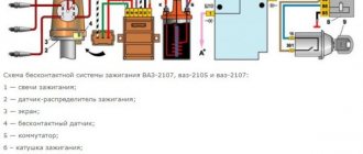
The contactless ignition system (BSI) of the VAZ 2107 includes:
- electronic (transistor) switch;
- transformer coil (two-winding);
- distributor (distributor) with Hall sensor, contact cover and slider;
- set of high-voltage wires;
- candles.
Each of these elements is a separate part and performs its functions independently of other components. Sparking in a VAZ 2107 engine with a non-contact ignition system occurs according to the following algorithm:
- When voltage is applied to the starter, its rotor begins to rotate the crankshaft, which, in turn, rotates the distributor shaft with the slider.
- The Hall sensor reacts to this rotation, registers the rotation of the distributor shaft and transmits a signal to the switch. The latter, having received a signal from the sensor, turns off the current supplied to the primary (low-voltage) winding of the coil.
- At the moment the current is turned off, a powerful voltage pulse occurs in the secondary winding of the transformer, which is transmitted through the central wire to the slider (moving contact) located at the end of the distributor shaft.
- The slider, moving in a circle, alternately comes into contact with four fixed contacts located in the distributor cover. At certain moments, it transfers tension to each of them.
- From the stationary contact, current flows through a high-voltage wire to the spark plug, causing sparking at its electrodes.
In a contactless ignition system, the role of a breaker is performed by a Hall sensor and a switch
Installation Tools
For all work carried out we will need:
- key to 38;
- open-end or socket wrench 13;
- a 12 V control light with two wires attached to it (each wire is approximately 20 cm long).
DETAILS: Photo report on replacing the cabin filter in Opel Corsa C. Instructions on how to change the cabin filter in Corsa
How to work with tags correctly
There are three marks on the engine block next to the crankshaft pulley, each with its own length. You can feel these marks from the driver's side, but only strictly with the engine not running, since the pulley rotates at high speed when the engine is running! The shortest of them will mean that the ignition is advanced by 10 degrees or 10 degrees to the top dead center of the piston in the cylinder, the middle mark by 5 degrees and short - 0 degrees.
Step-by-step description with photos and diagrams
- If during the work you accidentally messed up the ignition setting, then do not rush to remove the valve covers to understand when the compression stroke begins. Do the following: remove the spark plug in the first cylinder and plug the hole with a small, tight plug made from a rag soaked in water. Having made sure that no one is standing nearby and will not be harmed by the impromptu plug flying out, in short series we turn the crankshaft with the starter for literally a split second, turning the starter on and off, and at the moment when the plug flies out with a characteristic sound from the spark plug hole, we stop turning the starter.
- Now, turning the crankshaft a little at a time by the pulley nut with a 38 wrench, we ensure that the marks on the pulley and the cylinder block coincide with the middle mark, which means 5 degrees.
- We unhook the latches from the distributor cover and look at the direction of the slider: when it is positioned as in the photo, then half the job is already done. If not, then use an open-end wrench or a 13-socket wrench to unscrew the nut, remove the distributor and put everything back in the required position.
Required position of the distributor and slider relative to the cylinder block - We make a mark with a marker on the cylinder block to further optimize the ignition settings.
For ease of ignition settings - Now we connect our light bulb with one wire to the positive terminal of the ignition coil, and the second wire to ground. We remove the central wire of the coil from the distributor cover and fix it at a distance of approximately 1-5 mm from ground. This is done in order to prevent breakdown of the ignition coil to ground.
- Having turned on the ignition, slowly turn the ignition distributor housing (distributor) in the direction of movement clockwise and watch when the light goes out. If it didn’t burn, then we leave everything as is.
- Slowly rotate the distributor housing in the opposite direction, until the light comes on and use a 13 key to secure the housing.
- Turn off the ignition, return the distributor cap and the central wire to their place. Unhook the wires of the control lamp.
Video about setting up a VAZ 2107 (carburetor)
Removing the replacement part
Be sure to remove the terminal from the battery! After this, we disconnect all kinds of wiring from the coil, the main high-voltage wire. Now remove the cap from the distributor.
We must try to set the slider so that it is at an angle of 90 degrees towards the engine.
Draw a mark in advance (most conveniently on the cylinder block) so that you screw the new part to its original location.
Unscrew the nuts from the old distributor and remove it.
Switch
The commutator is necessary to create an electrical impulse by interrupting the constant supply of current from the battery to the primary winding of the coil. The BSZ VAZ 2107 uses a switching device of type 3620.3734. The working elements in it are ordinary bipolar transistors, which open the circuit when a signal is received from the Hall sensor.
Switch 3620.3734 is built according to a simple single-wire circuit, in which the device body is connected to the vehicle ground and, accordingly, to the negative terminal of the battery. The advantages of using this unit instead of a traditional breaker include:
- no need for maintenance or adjustment;
- high spark energy, which makes it easier to start the engine in the cold season, as well as the ability to use gasoline with a lower octane number;
- the presence of a stabilization system that protects the Hall sensor from voltage surges.
This switch has one drawback - low production quality. It happens that the device fails after just a few months of use. Its design is non-demountable, therefore, repair is impossible. That is why experienced owners of “Sevens” and other VAZs with a contactless ignition system carry spare switches in their cars. Fortunately, the part is inexpensive - 400–500 rubles.
UZSK
A concept such as UZSK characterizes the time when the breaker contacts are closed. In essence, this is an indirect characteristic of the accumulation of energy in the coil after the completion of spark formation. UZSK directly affects the amount of energy spent on sparking and, accordingly, on engine operation.
In cases where the distance between the contacts is small, the coil will not accumulate the necessary energy and the spark energy will be low, which will lead to interruptions in the operation of the motor. A large gap also leads to interruptions, since the contact breaking time is reduced and the coil does not have time to fully discharge.
Each ignition system has its own optimal UZSK, to ensure which, if necessary, the distributor must be checked and adjusted.
Which distributor is suitable for the VAZ-2107
On all carburetor rear-wheel drive VAZ cars, the device has almost identical components and a similar operating principle. Distributors for engines with a volume of 1200-1300 cc differ in that: - the drive rod is 7 mm shorter; - there is no vacuum ignition timing regulator;
DETAILS: Wiring diagram for the VAZ-2107 generator. Generator device
— the settings of the weights and springs of the centrifugal regulator are different. For engines with a volume of 1500-1600 cc, all distributors are suitable in terms of seating dimensions and characteristics. Only “Nivovskie” ones differ. They are tuned for stable traction at low speeds and the VAZ-2107 with such a distributor will accelerate slowly.
UOZ
This concept concerns the moment of ignition of a fuel assembly. The fact is that its combustion does not occur instantly, and often, to ensure optimal conditions for such a process, it must begin earlier than the piston reaches the TDC position. The OZ characterizes the time by which the appearance of a spark precedes the appearance of the piston in the TDC position.
It is constantly changing, and its value completely depends on the operation of the motor under specific conditions, i.e. depending on the load, vehicle speed, quality and type of fuel used. To ensure optimal combustion of the fuel assembly, the distributor contains a centrifugal regulator and is also connected to a vacuum regulator.
The main components of the distributor and a description of its operation
Device.
The distributor is assembled in a housing. Inside it, a contact group is mounted on a bearing: moving and fixed contacts or a Hall sensor (for contactless ignition). To correct the advance angle, the vacuum regulator can rotate the contact group at a small angle relative to the housing.
A capacitor is secured to the bottom of the housing with screws. A drive roller is installed on bushings in the center of the housing. Its bottom has splines with which it engages with the drive gear. In the upper part of the roller there are contact drive cams (for contact ignition) or a steel cup with four slots - a screen (for contactless ignition).
At the very top, on a steel platform, two weights and two springs of the centrifugal ignition regulator are installed. A plastic housing with a moving contact and noise suppression resistance of the high voltage distributor (slider) is screwed onto the top with two screws.
The entire structure is closed with a lid on two spring latches. The body and cover have a tongue and groove so that they fit together in only one position. The cover contains contact terminals for high voltage wires from the spark plugs and from the ignition coil.
Job.
The distributor is connected through the drive to the engine crankshaft and rotates with it. For two full revolutions of the crankshaft, the distributor shaft makes one revolution. This is due to the fact that our engine is four-stroke. When installing the distributor in place, the roller is oriented in strict accordance with the operating order of the engine.
This is done so that the contacts open and the spark jumps on the spark plug when the piston of each cylinder, compressing the combustible mixture, does not reach top dead center (TDC) by a few millimeters. This is called ignition advance. When the number of revolutions increases, the distance must be increased, and when it decreases, it must be decreased, which is what the centrifugal regulator does.
Its weights, under the influence of centrifugal force, which is greater the higher the engine speed, diverge to the sides and move the cams relative to the roller, making ignition “earlier.” When the engine speed decreases, the springs return the weights to their place and the ignition becomes “later”.
This is necessary to increase engine power and efficiency. In addition to the centrifugal one, a vacuum ignition timing regulator is also installed on the distributor. Its function is to fire “earlier” at low throttle opening angles and “later” at sharp throttle opening angles.
Repair of VAZ 2108 distributor (replacement of the vacuum regulator)
In distributors of VAZ 2108-09-099 cars, the VROZH quite often fails. Its performance can be checked without removing the PR from the engine - we suck in air through the hose, and if a vacuum is not created, the regulator should be changed.
The ignition timing regulator can be replaced on site without removing the distributor:
- unscrew the two screws of the distributor cover, and together with the high-voltage wires, move the cover to the side, disconnecting only the central wire;
- we pull out the slider, it can be removed by hand;
- Using a thin screwdriver, pull out the latch that secures the VROZH rod; you need to remove the fastening element carefully so as not to lose it;
- unscrew the 2 screws securing the “vacuum unit” and remove the device;
- We install the new part in place and put everything back together.
Replacing the VROZH can also be done by removing the distributor, which will even be more convenient. Remove the distributor as follows:
- disconnect the high-voltage wires from the PR cover;
- use a thin screwdriver to hook the retaining springy wire on the connector and remove the plug going to the distributor from the bottom left;
- we pull off the hose from the VROZH, make a mark on the PR body or notice how it stood;
- unscrew the three nuts that secure the distributor itself, and then remove the breaker - distributor.
Reinstalling the distributor is simple - the camshaft spline has a groove shifted to one side, and therefore the PR is installed in only one position, it is impossible to make a mistake here. During installation, you need to pay attention to the rubber O-ring - if the rubber has hardened, the part must be replaced. And in any case, the seal should be coated with an oil-resistant sealant, in which case oil leakage will be almost 100% avoided.
Distributor
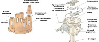
The ignition distributor (distributor) is designed to transmit high-voltage current pulses that come from the coil to the spark plugs. The distributor consists of:
- aluminum body;
- shaft;
- Hall sensor;
- vacuum and centrifugal ignition timing regulators;
- runner;
- covers with four fixed contacts.
In “sevens” with contactless ignition, distributors of type 38.3706 are used.
Why do you need a distributor?
The ignition system is a critical part of a gasoline engine. The operation of the latter is based on the timely combustion of the fuel-air mixture (FA), for which purpose a high-voltage voltage is specially generated, which is then supplied to the spark plugs. A spark is formed on them, causing combustion of the fuel assemblies, as a result of which the engine performs useful work. This is roughly how you can briefly describe the operating principle of a gasoline internal combustion engine.
All these processes require a distributor. If we evaluate its role during the operation of the ignition, it should be noted that it:
- initiates the onset of sparking due to the opening of the breaker contacts (in more modern car models, for example, VAZ 2109, 2106, 2107, 2108 of the last years of production, a Hall sensor is used for these purposes);
- directs the high voltage generated in the ignition coil to the desired spark plug;
- changes the beginning of the moment of spark formation depending on the driving modes and the fuel used, for which vacuum centrifugal regulators are used;
- provides accumulation and discharge of energy in the reel.
A functional ignition diagram will allow you to better understand what the distributor is used for and how it works:
Installing an electronic BSZ instead of a contact one
Today it is very rare to find a “seven” with contact ignition. With the arrival on sale of switches, distributors and coils for electronic spark generation systems, owners of classics began to massively re-equip their cars.
DETAILS: Replacing the air filter on a Hyundai Solaris with your own hands
What is included in the BSZ kit
In addition, you will need spark plugs (preferably new ones) with a gap of 0.7–0.8 mm and a set of high voltage wires. Coil type B-117A (used in a contactless system) is not suitable for electronic ignition. Its characteristics do not correspond to those of other equipment in the circuit.
Preparation
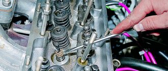
Before installing a new VAZ-2107 distributor for a contact ignition system, you need to adjust the gap between the contacts of the breaker. It is more convenient to do this with the device removed from the car. We check the gap with a flat feeler gauge. The value is set from 0.35 to 0.45 mm.
In this case, the protrusion of the cam should move the moving contact away from the stationary contact as much as possible. We adjust by slightly loosening the screws, and then tighten them more firmly and check the gap again. Contacts that have worked hard may have a protrusion on one and a depression on the other, which interferes with adjustment.
Before removing the old distributor, mark its position relative to the cylinder block with a marker. You also need to accurately mark the position of the moving contact (slider) relative to the body. If all this is not done, the settings will be violated and the engine will not start.
Installation
Having established exactly the same position of the roller in the body on the new distributor, carefully insert it into the hole in the block, slightly turning the roller to align the splines. Having “planted” the device in place by rotating the body relative to the block, we set the approximate advance angle, as on the old distributor.
Secure with a washer and nut, but not too tight. Now you need to plug in the high voltage wires. This is easy to do - each contact on the distributor cover has the number of the cylinder to which it needs to be connected. We connect the wire from the ignition coil to the central terminal.
The wires should fit tightly, with a slight tension, the protective caps should be pushed all the way down. Don’t get carried away, don’t bend the petals of the wire tips too much, otherwise later, when you try to remove them, you’ll tear off the wires “with their roots”! A wire goes from the contact wire to the “K” terminal of the ignition coil, usually it is green.
If your VAZ-2107 is equipped with a contactless ignition system, then you need to connect a connector with three wires. Having plugged it into the socket, check the fit of the wires; it happens that they “crawl out” of their places and the device does not work. Everything is done, the new distributor is installed and ready for use.
Symptoms of a problem
Of course, repair of the distributor is carried out only after it has been diagnosed.
Listed below are the main symptoms of a distributor malfunction, in which it is necessary to disassemble and check the mechanism:
- the car began to jerk while driving;
- the engine basically won’t start;
- when the speed increases, detonation may be heard (knock of “fingers”);
- it takes longer to increase speed;
- Gasoline consumption has increased.
Of course, these symptoms may indicate other problems. Therefore, before repairing a disassembled unit, you need to know how to set, how to adjust and how to check the distributor.
To check it, you need to disassemble it and pay attention to the condition of the following components:
- slider;
- oxidized or burnt distributor cover contacts;
- failure of the Hall sensor (its bearing element could fail or become jammed);
- distributor capacitor;
- presence of cracks on the device body;
- stuffing box;
- Repair of the ignition distributor should also be carried out if engine fluid gets into its structure.
Distributor for car
A device function called a slider
ATTENTION! A completely simple way to reduce fuel consumption has been found! Don't believe me? An auto mechanic with 15 years of experience also didn’t believe it until he tried it. And now he saves 35,000 rubles a year on gasoline! Read more"
The slider is located in the ignition distributor. You can find it right under the lid. By design, runners are quite simple devices consisting of plates (central and spacer). Despite the fact that the models of distributor runners are different, they all have the same design.
These devices have an important function regarding sparking. We can say that the proper operation of the internal combustion engine directly depends on the slider.
You should know that the distributor rotor is a part of old cars equipped with a carburetor engine system. The slider is made of plastic and has a high-voltage contact inside. When the distributor operates and rotates, the contact of the slider is in direct contact with the contacts of the cover. Thus, the spark that is so necessary for the car is set.
In technical terms, the distributor rotor is needed to transmit high voltage current. The transmission goes from the ignition coil to the spark plugs through armored wires.
The rotor is fixed directly to the distributor drive (shaft), and the rotation is set in such a way that for 1 revolution of the runner there are 2 revolutions of the crankshaft. It is in this way that the discharge is transmitted to the spark plugs in a strictly defined order.
On a distributor drive, the slider is fixed rigidly so that it does not jump off when the shaft rotates. When rotating, the side contact of the rotor contacts the CG (contact group) pressed into the distributor cap.
Interesting. The distributor cap is in the same position regularly. It does not move, but the sliding contact, “running” next to the electrodes of the cover, forms an alternating and short-term electric arc. This also explains the transmission of the discharge.
On some cars, ignition systems have two working contacts on the slider. This is, in principle, a working classic Twin Spark ignition circuit from the Italian company Fiat. One of the contacts is implemented closer to the center, the other - as far as possible. In this way, the contacts correspond to the cover electrodes, packaged according to the same principle. And most importantly: this scheme ensures complete isolation of the CGs from each other.
Twin Spark is considered one of the first systems used for effective afterburning of fuel in the combustion chamber of a car. The system has a simple design, but is very effective and economical.
Examination
The easiest way to test a switch is to try replacing it with a known good one. But this can only be done if a working switch is at hand. It is not advisable to buy a new unit just to test the operation of the old one. There is a cheaper and not particularly complicated way. To test the switch, you only need a standard set of keys and a test lamp. This is enough to verify the presence or absence of pulses supplied to the ignition coil. Before checking the switch, make sure that “plus” is supplied to it and the ignition coil. Also check the connection contacts of the Hall sensor and the functionality of the sensor itself. Checking the VAZ 2107 ignition switch is performed as follows:
- turn off the ignition;
- unscrew the nut on the ignition coil and disconnect the brown wire marked “K” (the wire goes to connector “1” on the switch);
- connect a test lamp to the gap between the wire terminal and the coil terminal;
- turn on the ignition;
- turn the key and start the starter.
A flashing light indicates a working switch. If the lamp does not light, the switch needs to be replaced.
Replacing a VAZ 2107 switch
To replace the switch, you must complete the following steps:
- turn off the ignition;
- disconnect the wire block from the switch connector;
- unscrew the fastening nuts;
- remove the old switch and put a new one in its place;
- tighten the fastening nuts;
- connect the wire block to the connector.
At this point, the replacement of the VAZ 2107 switch is completed and you can check the operation of the ignition by trying to start the engine.
Repair of distributor for VAZ 2101-VAZ 2107
Welcome! The distributor is an integral part of the car, even if you remove the cover from it, the car simply won’t start, so this unit is definitely needed on carburetor cars, although in injection systems it has already been abandoned and a crankshaft position sensor is used instead, if it fails which, the car will also not start.
Note! To repair this unit, take: A set of wrenches, as well as two types of screwdrivers, a set of flat feeler gauges, buy a set of flat feeler gauges at a car store, or specifically buy feeler gauges for 0.35, 0.40, 0.45, you will need them, another hammer and one mandrel for pressing out and Buy one for pressing distributor bearings, and take tweezers (if you have them) too!
Repair
Before checking the cover or other structural elements, you need to prepare for repair work. Repairing the cover, replacing the distributor oil seal and other tasks to restore functionality are carried out after setting the marks. How to set marks - marks are applied to the device body, its cover, as well as the drives of auxiliary elements - this will allow you to maintain the required ignition timing without adjustment. Also, before removing the assembly, mark the position of the wires that go to the spark plugs, since if you mix them up during further installation, this may lead to damage to the mechanism.
As for the repair itself, it is performed like this:
- After dismantling the device, the cover is diagnosed. If you notice that it is broken, then it will have to be replaced with a functional one.
- Next, you need to check the distributor slider - it needs to be changed if the fuse has melted or rust and fumes have appeared on the element.
- After these steps, the dust shield is dismantled - first, the voltage terminal is removed, after which the two bolts securing the Hall sensor support plate are unscrewed, and the plate itself is also removed after these steps. Having done this, remove the retaining ring from the plate pin, unscrew the bolts securing the vacuum corrector, and remove the component itself. Then the support plastic is pulled out and its bushing is diagnosed - there should be no signs of damage on it.
- Next, remove the spring ring that secures the coupling pin. If you see that the condition of the ring is sad, it needs to be changed, because otherwise it will be of no use. Next, you need to knock out the pin from the coupling - it can only be replaced if the pins have worn out.
- Many car owners are interested in the question of how to check the capacitor. This element can also fail, so check the capacitor first. You will need to prepare a multimeter. Diagnostics is carried out by a tester.
- A centrifugal control device with a roller is removed from the structure. The distributor is replaced if there are gaps, signs of wear and other damage (the author of the video is Roman Romanov).
What is ignition timing?
For the ignition to work correctly, the following condition must be met: sparking must occur at the moment when the piston is at TDC. This should be a compression stroke. This moment should be the flash point.
| Options | Units | Classical | Contactless |
| Spark energy | mJ | 20 | 60 |
| Secondary voltage rise time from 2 to 15 kV | mks | 30 | 20 |
| Secondary voltage max | kV | 26 | 29,5 |
| Spark duration | ms | 1,5 | 2 |
However, that's not all. The time it takes for the fuel mixture to completely burn must also be taken into account. Therefore, the spark plugs must create an impulse with some advance, which is called the advance angle. As a result, the mixture reaches the peak of combustion, and the cylinder begins to move downward.
If sparking occurs earlier, then such ignition is called earlier, and if late, then later. Early leads to detonation. This is why the engine quickly overheats and becomes inefficient, although fuel consumption can sometimes be greatly reduced. This can be determined by the spark plug electrodes, which are covered with a white coating. With late ignition, power is noticeably lost, and black smoke comes out of the exhaust pipe, which indicates that gasoline, without having time to burn in the cylinder, burns out in the exhaust system.
The spark plugs, in this case, turn black. Popping noises in the exhaust pipe can also tell this. Late ignition means that the spark plugs are simply flooded with fuel, which does not burn or burns incompletely. When they are flooded, they do not work.
Ignition systems are divided into 3 groups:
Contact ignition system
Contact ignition system
Contactless ignition system
Contactless ignition system
Electronic ignition system (microprocessor ignition system)
Electronic ignition system
Pros and cons of contactless ignition
Pros and cons of contact ignition
Pros and cons of an electronic ignition system
Types of faults
As a rule, if the distributor slider is in order, then the car engine starts the first time, without any problems. But when difficulties are observed with the plant, this indicates a damaged or broken rotor (provided that the problem is not elsewhere).
The most common malfunction of the distributor slider is its breakdown. It can be external or internal. Obviously, the external one is determined by noticeable signs - a black mark, the internal one must be checked by the presence of a spark (details below).
The breakdown occurs due to metallization of the channel. For preventive purposes, metallization should be checked regularly. This is done using a multimeter or other similar device. The channel is checked for moment of resistance. The probes of the device are connected to the place of the slider where there is doubt about breakdown.
You should know that the spark can escape either completely or partially through the formed channel.
Design and characteristics of a slider with a resistor
The slider (rotor) with a resistor consists of several parts: a cast body, two rigidly fixed contacts (central, resting on a corner in the distributor cover, and a side one) and a cylindrical resistor located in a special recess. The housing is made of electrically insulating material; the contacts are usually fixed to it using rivets. The contacts have spring plates, between which a resistor is clamped. In the lower part of the slider body there is a shaped channel for fixation on the ignition distributor shaft.
According to the method of installing the resistor, there are two types of sliders:
- With replaceable resistor;
- With a non-replaceable resistor - the part is filled in a recess with a special insulating compound based on epoxy resin or glassy materials.
The runners use powerful resistors of a special design with end leads, designed for installation between spring contacts. In domestic cars, resistors with a resistance of 5.6 kOhm are most often used, but in various sliders you can find resistors with a resistance of 5 to 12 kOhm.
Depending on the type of distributor, the slider can be simply mounted on the distributor shaft (usually such parts are T-shaped), or mounted with two screws on the ignition timing regulator (such parts are made in the form of a flat cylinder). In both cases, the resistor is mounted on the outside of the slider, which allows access to its inspection and, if possible, replacement.