This contact assignment is suitable for Electronic Control Units BOSCH M7.9.7 / January 7.2, used on LADA (VAZ) 2111, 2114, 2109 and others, on which engines 21114 and 21124 were installed.
| № | 8 valve engine (21114) | 16 valve engine (21124) | Car with two oxygen sensors (Euro 3) |
| 1 | Second cylinder ignition coil control output | ||
| 2 | Ignition coil control output for cylinders 2-3 | Third cylinder ignition coil control output | |
| 3 | Ignition coil weight | ||
| 4 | Fourth cylinder ignition coil control output | ||
| 5 | Ignition coil control output for cylinders 1-4 | Ignition coil control output of the first cylinder | |
| 6 | Injector pulse of the second cylinder | ||
| 7 | Injector pulse of the third cylinder | ||
| 8 | Tachometer output | ||
| 9 | Not used | ||
| 10 | Fuel consumption signal | ||
| 11 | Not used | ||
| 12 | Terminal 30. Constant power supply from battery | ||
| 13 | Terminal 15. Power from the ignition switch | ||
| 14 | Main relay control output | ||
| 15 | Crankshaft sensor input (A) | ||
| 16 | Throttle position sensor signal input (C) | ||
| 17 | Throttle sensor ground (B) | Weight TPS, Rough Road Sensor | |
| 18 | Oxygen sensor 1 signal input (A) | ||
| 19 | Knock sensor input | ||
| 20 | Knock sensor weight | ||
| 21 | Not used | ||
| 22 | Not used | ||
| 23 | Not used | ||
| 24 | Not used | ||
| 25 | Only on Bosch - high current output, reserve | ||
| 26 | Only on Bosch - high current output, reserve | ||
| 27 | Injector pulse of the first cylinder | ||
| 28 | Not used | Second oxygen sensor heater control output | |
| 29 | Not used | Engine cooling fan control output | |
| 30 | Not used | ||
| 31 | Check lamp | ||
| 32 | Power supply (+5V) throttle position sensor | Power supply for TPS and rough road sensor | |
| 33 | Power supply (+5V) of the Mass Air Flow Sensor | ||
| 34 | DPKV input, contact “B” | ||
| 35 | Coolant Temperature Sensor Ground | Weight of Coolant Temperature Sensor, Mass Air Flow Sensor and two Oxygen Sensors | |
| 36 | Mass Air Flow Sensor Weight | ||
| 37 | Signal input from Mass Air Flow Sensor | ||
| 38 | Not used | ||
| 39 | Signal input from Coolant Temperature Sensor | ||
| 40 | Signal input from intake air temperature sensor | ||
| 41 | Not used | ||
| 42 | Not used | Signal input from Rough Road Sensor | |
| 43 | Not used | ||
| 44 | +12V power input after main relay | ||
| 45 | Phase sensor power output (Camshaft sensor) | ||
| 46 | Canister purge valve control output | ||
| 47 | Fourth cylinder injector pulse | ||
| 48 | Oxygen sensor heater control output | ||
| 49 | Not used | ||
| 50 | Controlling the additional starter relay | ||
| 51 | ECU weight | ||
| 52 | Not used | ||
| 53 | ECU weight | ||
| 54 | Not used | ||
| 55 | Not used | Second oxygen sensor signal input | |
| 56 | Not used | ||
| 57 | Input for encoding calibration data options. The controller memory can store two options for calibration data, one of which is selected by connecting or not connecting this contact to ground in the wiring harness. In the absence of a connection to ground, this contact is supplied with on-board voltage through the internal resistor of the controller. | ||
| 58 | Not used | ||
| 59 | Speed Sensor Signal | ||
| 60 | Not used | ||
| 61 | Mass of Output Cascades | ||
| 62 | Not used | ||
| 63 | +12V power input after main relay | ||
| 64 | Contact "D" of the Idle Air Controller | ||
| 65 | Idle Air Control Terminal "C" | ||
| 66 | Idle Air Control Terminal "B" | ||
| 67 | Idle Air Control Terminal "A" | ||
| 68 | Output to control the engine cooling fan relay | ||
| 69 | Air conditioner relay control output | ||
| 70 | Output for controlling the fuel pump relay | ||
| 71 | K‑Line (Diagnostic line) | ||
| 72 | Not used | ||
| 73 | Not used | ||
| 74 | Not used | ||
| 75 | Air conditioner request signal | ||
| 76 | Request to turn on power steering | ||
| 77 | Not used | ||
| 78 | Not used | ||
| 79 | Phase sensor signal input | ||
| 80 | Weight of output stages | ||
| 81 | Not used | ||
VAZ-2112 diagram
The VAZ-2112 car was produced at AvtoVAZ from 1998 to 2009, in Ukraine from 2009 to 2014. The following are color wiring diagrams (injector and carburetor) with a description of all elements for various modifications. The information is intended for self-repair of cars. Electrical circuits are divided into several blocks for ease of viewing via a computer or smartphone; there are also circuits in the form of a single picture with a description of the elements - for printing on a printer in one sheet.
To diagnose and repair yourself, first look to see if everything is okay with the generator. Is it put on well and does not sag? This procedure must be done with all versions of the fuel system, both carburetor and injection. We check the fuses according to the electrical diagram. The reverse side of the safety block cover will also be of great help. There are clues there that the diagram will help you decipher. Replace the burnt out element and try to start the car again. You need to check whether the battery terminals are tightly connected and whether they are oxidized. Is the wire going from the battery to the generator and to the starter damaged?
Why the scanner does not connect to the VAZ 2110 ECU and how to fix it
Often, car owners are faced with the problem of the inability to connect a device with a control module, why does this happen:
- You purchased a low-quality adapter. In this case, we are not talking about the firmware, but rather about the inoperability of the hardware, which is typical for defective devices. If the board fails or is initially inoperative, then it will be impossible to check the operation of the motor. Accordingly, how to connect to the control unit.
- Damaged or defective cable that prevents device communication. It is necessary to diagnose the wire to identify damage.
- Another reason why there may be no connection is due to bad firmware. If the software version is too old, it will be impossible to synchronize the device with the car.
Modifications of the VAZ-2112 car
VAZ-21120 . Modification with a 16-valve injection engine with a volume of 1.5 liters and a power of 93 horsepower. 14-inch wheels were installed on the car. This modification has a problem with valves bending when the timing belt breaks. The problem can be solved by increasing the depth of the grooves in the piston bottoms.
VAZ-21121 . The car was equipped with a VAZ-21114 8-valve injection engine with a volume of 1.6 liters and a power of 81 horsepower.
VAZ-21122 . Budget modification with an 8-valve injection engine VAZ-2111. The car was produced without electric windows, the wheels were 13 inches in size, and the brakes were unventilated from a VAZ-2108 car.
VAZ-21123 Coupe . Three-door, five-seater hatchback. The only two doors for entering the car are 200 millimeters wider than those of the five-door hatchback, and they are mounted on new, durable hinges. The rear arches of the car have become wider. The engine was installed with a 16-valve injection engine with a volume of 1.6 liters and a power of 90 horsepower. The car was produced from 2002 to 2006 in small quantities, the reason for this was the high cost of the car.
VAZ-21124 . Modification with a 16-valve injection engine VAZ-21124 with a volume of 1.6 liters. Produced from 2004 to 2008. For this type of engine, the problem with valve bending was solved. To do this, the depth of the grooves in the piston heads was increased (up to 6.5 mm). In addition, the design of the cylinder block was changed to achieve a working volume of 1.6 liters, for which its height was increased by 2.3 mm, and the radius of the crankshaft was increased by 2.3 mm accordingly. There were also a number of other minor changes.
VAZ-21128 . The luxury version of the car, produced by Super-auto JSC, was equipped with a 16-valve VAZ-21128 engine with a volume of 1.8 liters and a power of 105 horsepower.
VAZ-2112-37 . A racing modification of the VAZ-2112, prepared for the “ring” in the Lada Cup qualifying group. The car was equipped with a 1.5-liter VAZ-2112 engine with a power of 100 horsepower. The racing car was equipped with a safety cage, an external aerodynamic kit and a front extension of the strut support cups.
VAZ-2112-90 Tarzan . All-wheel drive modification with a VAZ-2112 body on a frame chassis with transmission and suspension parts from a VAZ-21213 Niva. It was also equipped with a 1.7 or 1.8 liter engine from the Niva.
Article: 346027
Order code: 095401
- Buy with this product
- show more
Buy analogues
- There are no reviews for this product yet.
Schematic electrical diagrams, connecting devices and pinouts of connectors
The fuel pump on a car is designed to supply fuel to the combustion chamber. Its operation is controlled using a relay. On a VAZ (depending on the model), the fuel supply unit can be electrical or mechanical - it all depends on the fuel supply system. On a fuel-injected car, the fuel pump is located in the tank. When the ignition is turned on, voltage is supplied to the terminals of the unit and it begins to pump fuel. If the required pressure is created in the system, the relay automatically turns off the fuel pump - the engine is ready to start.
When the ignition is turned on, the relay creates pressure in the fuel lines by turning on the fuel pump (BN) for a couple of seconds. After this, the BN will work either when the engine is cranked by the starter, or when the engine is running.
Sometimes this system needs repairs - there is nothing complicated here, and the editors of the 2Skhema.ru website will tell you how to do it yourself. Let's start with the BN pinout, then we will indicate it on the diagrams and at the end there will be instructions for replacing the fuel supply elements.
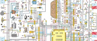
Electrical diagram of VAZ-2112
Designations: 1 – Headlight, 2 – Klaxon, 3 – Main radiator fan, 4 – Starter, 5 – Battery, 6 – Generator 2112, 7 – Gearbox limit switch (reverse), 8 – Actuator in the front passenger door, 9 – Power window enable relay, 10 – Starter relay, 11 – Heater fan, 12 – Electric heater partition drive, 13 – Main pump, 14 – Washer reservoir sensor, 15 – Driver’s door actuator, 16 – Front passenger window selector, 17 – Unlock button fifth door, 18 – Heater fan resistance unit, 19 – Main wiper motor, 20 – Driver’s window lift selector, 21 – Front passenger’s window lift motor, 22 – Central locking, 23 – Exterior light switch, 24 – Brake fluid leakage sensor, 25 – Pump additional, 26 – Driver's window lift motor, 27 – PTF on indicator, 28 – PTF switch, 29 – Dashboard, 30 – Heated glass on indicator, 31 – Heated glass switch, 32 – Steering column selector switch, 33 – PTF relay, 34 – Ignition switch, 35 – Main fuse block, 36 – Illumination of heater controls, 37 – Hazard warning button, 38 – Heater control controller, 39 – Glove compartment lighting, 40 – Glove compartment lid end cap, 41 – Cigarette lighter, 42 – BSK – display unit, 43 – Ashtray illumination, 44 – 12V socket, 45 – Instrument lighting switch, 46 – Actuator in the right rear door, 47 – Right rear passenger window selector, 48 – Clock, 49 – Right rear passenger window motor, 50 – Brake limit switch (closed – pedal is pressed), 51 – Left rear passenger window motor, 52 – Left rear passenger window selector, 53 – Actuator in the left rear door, 54 – Turn signal, 55 – Handbrake limit switch (closed – handbrake on), 56 – Rear wiper motor , 57 – Navigator's lamp, 58 – Interior lamp, 59 – Temperature sensor in the heater, 60 – Limit switch for the open front door, 61 – Limit switch for the open rear door, 62 – Trunk light, 63 – Rear optics (on the body), 64 – Rear optics (on the fifth door), 65 – License plate illumination.
The letters indicate the terminals to which it is connected: A – Front speaker on the right, B – Radio, C – Injector harness, D – ESD diagnostic connector, D – Front left speaker, E – Diagnostic connector for the heater controller, G – Rear right speaker, W – Rear left speaker, I – BC connector, K – glass heater thread, L – fifth door actuator, M – Additional brake light.
Wiring diagram VAZ-2112 injector 16 valves - full view
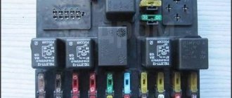
How to remove the mounting block - all steps in one video
Left: If the turn signals work properly but the hazard warning lights do not turn on, the cause is usually a faulty hazard warning light switch. If you press the switch firmly several times, most often it will start working normally. If this does not happen, then remove the switch (2), squeezing its locking tabs and removing it from the groove, check the contacts of the pin connection (1). Right: When installing the brake light switch (2), it must be pressed against the pedal support (3) so that the switch pin also presses the switch when the pedal (4) is released. For perfect operation, the pin block (1) must be correctly connected.
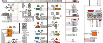
VAZ-21124 engine control circuit
Connection diagram of the VAZ-21124 engine control system with distributed fuel injection to Euro-2 emission standards (controller M7.9.7): 1 - ignition coils; 2 — nozzles; 3 - controller; 4 - main relay; 5 - fuse connected to the main relay; 6 — cooling system electric fan relay; 7 - fuse connected to the cooling system electric fan relay; 8 - electric fuel pump relay; 9 - fuse connected to the electric fuel pump relay; 10 — mass flow and air temperature sensor; 11 — throttle position sensor; 12 — coolant temperature sensor; 13 — solenoid valve for purge of the adsorber; 14 — oxygen sensor; 15 — knock sensor; 16 — crankshaft position sensor; 17 — idle speed regulator; 18 — immobilizer control unit; 19 — immobilizer status indicator; 20 - phase sensor; 21 — vehicle speed sensor; 22 — electric fuel pump module with fuel level sensor; 23 — oil pressure warning lamp sensor; 24 — coolant temperature indicator sensor; A - block connected to the wiring harness of the ABS cabin group; B — diagnostic block; B - block connected to the air conditioner wiring harness; G - to the “+” terminal of the battery; D — to the side door wiring harness block; E - block connected to the instrument panel wiring harness; G1, G2 - grounding points; I - the order of conditional numbering of plugs in the block of the immobilizer control unit; II - the order of conditional numbering of contacts in the diagnostic block.
Connection diagram of the VAZ-21124 engine control system with distributed fuel injection under Euro-3 toxicity standards (controller M7.9.7): 1 - ignition coils; 2 — nozzles; 3 - controller; 4 - main relay; 5 - fuse connected to the main relay; 6 — cooling system electric fan relay; 7 - fuse connected to the cooling system electric fan relay; 8 - electric fuel pump relay; 9 - fuse connected to the electric fuel pump relay; 10 — mass flow and air temperature sensor; 11 — rough road sensor; 12 — throttle position sensor; 13 — coolant temperature sensor; 14 — idle speed regulator; 15 — control oxygen sensor; 16 — diagnostic oxygen sensor; 17 — solenoid valve for purge of the adsorber; 18 — knock sensor; 19 — crankshaft position sensor; 20 — immobilizer control unit; 21 — immobilizer status indicator; 22 - phase sensor; 23 — vehicle speed sensor; 24 — electric fuel pump module with fuel level sensor; 25 — oil pressure warning lamp sensor; 26 — coolant temperature indicator sensor; A - block connected to the wiring harness of the ABS cabin group; B — diagnostic block; B - block connected to the air conditioner wiring harness; G - to the “+” terminal of the battery; D — to the side door wiring harness block; E - block connected to the instrument panel wiring harness; G1, G2 - grounding points; I - the order of conditional numbering of plugs in the block of the immobilizer control unit; II - the order of conditional numbering of contacts in the diagnostic block.
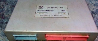
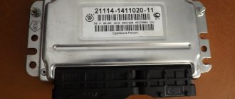
ECU BOSCH 21114-1411020-30 M 7.9.7+.
Dear customers, in order to avoid errors when sending an electronic engine control unit (ECU, ECM, controller), indicate your car model, year of manufacture and number of valves in the “Comment” line.
The Electronic Engine Control Unit (ECU) is the “computer” that controls the entire vehicle system. The ECU affects both the operation of an individual sensor and the entire vehicle. Therefore, the electronic engine control unit is very important in a modern car.
The controller firmware in the photo and availability in the warehouse may differ. When ordering, please specify the required firmware.
The following firmware versions are available:
Bosch controllers 21114-1411020-30 M7.9.7 and M7.9.7+
| Software ID | ECU | VAZ number | Engine | Toxic standards | Note |
| Bosch M7.9.7 | |||||
| B104DN15 | Bosch M7.9.7 | 21114-1411020-30 | 21114 | E-2 | 1 Serial version 1.6 Attention! "Glitchy" software. |
| B104DP16 | Bosch M7.9.7 | 21114-1411020-30 | 21114 | E-2 | 2 Serial version 1.6 |
Bosch M7.9.7 new hardware implementation (M7.9.7+)
| B104DQ17 | Bosch M7.9.7+ | 21114-1411020-30 | 21114 | E-2 | 1 Serial version for new hardware implementation |
| B104DR17 | Bosch M7.9.7+ | 21114-1411020-30 | 21114 | E-2 | 2 Serial version for new hardware implementation |
Product features: Electronic engine control unit (catalog designation “BOSCH”, 0 261 207 827, Motronic 1126 6716 B104DR17 France), using various signals from engine sensors, controls the composition and amount of fuel supplied to the engine.
INFORMATION LETTER No. 14-2005-I
Interchangeable controllers: January 7.2. 21114-1411020-32 Euro – 2, January 7.2. 21114-1411020-31 Euro – 2 .
VAZ 2113-2115 after 2006, VAZ-21101; VAZ-21104 their modifications.
Varieties of electronic engine control systems (ECM, controllers), which are installed on different models of the VAZ family car.
How does a malfunction of the electronic engine control unit (ECU, ECM, controller) manifest itself in a VAZ family car.
How to independently replace the electronic engine control unit (ECU, ECM, controller) on a VAZ family car.
With the AvtoAzbuka online store, repair costs will be minimal.
Don't forget to share the information you find with your friends and acquaintances, because they may also need it - just click one of the social networking buttons located above.
January 5.1.x
Already in 2003, the fourteenth began to be equipped with improved brains (which, by the way, were suitable for both the thirteenth and fifteenth) - this is “January 5.1x”. this controller was produced in three variations regarding fuel injection: simultaneous injection, pair-parallel injection and phased injection.
By the way, this type of brain matches the parameters well with “VS (Itelma) 5.1” or “BOSCH M1.5.4”, which allows you to interchange domestic firmware with foreign ones. Below are models of all three lines of brains.
The VAZ 2114 control unit, represented by different models of the same line, will be built on a single base, and the models will differ only in the switching of injectors or heating of the DC.
For "January":
January 5.1.x
Let's compare architectures
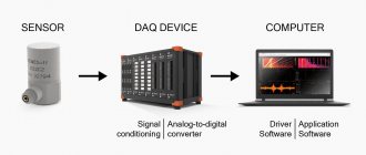
At the moment, there are many different ADC architectures in the world. Each of them has its own advantages and disadvantages. There is no architecture that would achieve the maximum values of all the parameters described above. Let's analyze what maximum speed and resolution parameters the companies producing ADCs were able to achieve. We will also evaluate the advantages and disadvantages of each architecture (you can read more about the various architectures in the article on Habr). Architecture comparison table
| Architecture type | Advantages | Flaws | Maximum resolution | Maximum sampling rate |
| flash | Fast converter. The conversion is carried out in one clock cycle. | High power consumption. Limited resolution. Requires a large crystal area (comparators). It is difficult to coordinate a large number of elements (as a result, low yield). | 14 bit 128 kSa/s AD679 | 3 bit 26 GS/s HMCAD5831 |
| folding-interpolated | Fast converter. The conversion is carried out in one clock cycle. Requires fewer comparators due to preliminary “convolution” of the entire processing range into a narrower range. Occupies less space. | Errors associated with the nonlinearity of the convolution block. Delay for establishing levels in the convolution block, which reduces the maximum fs. Medium resolution. | 12 bit 6.4 GS/s ADC12DL3200 | 12 bit 6.4 GS/s ADC12DL3200 |
| SAR | High accuracy. Low power consumption. Easy to use. | Limited speed. | 32 bit 1 MSa/s LTC2500 | 10 bit 40 MSa/s XRD64L43 |
| pipeline | Fast converter. Highest accuracy among fast ADCs. Doesn't take up a large area. Has lower consumption among similar fast converters. | Pipeline delay. | 24 bit 192 kSa/s AK5386 | 12 bit 10.25 GS/s AD9213 |
| dual-slope | Average conversion accuracy. Simplicity of design. Low consumption. Resistance to changes in environmental factors. | Processes low frequency Signals (low fs). Mediocre resolution. | 12+sign bit 10 S/s TC7109 | 5+sign bits 200 kSa/s HI3-7159 |
| ∑-Δ | The highest conversion accuracy thanks to the “Noise shaping” effect (specific filtering of quantization noise) and oversampling. | Cannot work with wideband signal. | 32 bits 769 kSa/s AK5554 | 12 bit 200MS/s ADRV9009 |
Why ELM 327 does not connect to the VAZ 2110 ECU
So, why doesn't ELM327 see the ECU? What should I do so that the device can connect and see the block? Today you can find many different adapters for testing a vehicle on sale. If you buy an ELM327 Bluetooth, most likely you are trying to connect a low-quality device. Or rather, you could have purchased an adapter with an outdated version of the software.
ELM327 Bluetooth devices with outdated firmware use a different Bluetooth module that allows you to interact with two of the available six protocols. Accordingly, you can synchronize the device with a smartphone, but when you try to connect the device to the control unit, it will inform you that there is no connection with the ECU.
So, for what reasons does the device refuse to connect to the block:
- The adapter itself is of poor quality.
- Problems can be with both the device’s firmware and its hardware. If the main microcircuit is inoperative, it will be impossible to diagnose the engine operation, as well as connect to the computer.
- Bad connection cable. The cable may be broken or inoperative itself. The wrong version of the software is installed on the device, as a result of which it will not be possible to achieve synchronization (the author of the video about testing the device is Rus Radarov)
If you own a device with the correct firmware version 1.5, where all six of the six protocols are present, but the adapter does not connect to the ECU, there is a way out. You can connect to the unit using initialization strings, which allow the device to adapt to the commands of the machine’s motor control unit. In particular, we are talking about initialization lines for diagnostic utilities HobDrive and Torque for vehicles that use non-standard connection protocols.
Appearance and body structure
As for the dimensions, the VAZ-2112 (16 valves) decreased in length by 93 mm. This change occurred in the rear overhang area. But despite all this, the size of the wheelbase did not transform. The body length was 4170 mm. And the height of 1676 mm and width of 1430 mm remained classic for the “tenth” family. The top line on this body very smoothly transforms into a rather small rear overhang and a huge wing. This design allowed the developers to make the car more manageable.
The one hundred percent zinc-coated body of the “10”, which at one time became very popular, is still susceptible to corrosion. Many owners of new cars did not consider it necessary to perform anti-corrosion treatment. The bottom was rapidly rusting to holes.
Description of "brains"
The VAZ 2114 ECU is an on-board computer of the vehicle, designed to control the main systems of the car. The parameters of the control module affect both the functionality of certain regulators and the operation of the engine as a whole.
That is, the importance of this system cannot be denied
Controller Location
In VAZ 2114 and VAZ 2115 cars, the control module is installed under the center console of the car, in particular, in the middle, behind the panel with the radio. To get to the controller, you need to unscrew the latches on the side frame of the console. As for the connection, in Samar modifications with a one and a half liter engine, the mass of the ECU is taken from the power unit housing, from the fastening of the plugs located to the right of the cylinder head.
Location of the ECU in the Chetyrka
In cars equipped with 1.6- and 1.5-liter engines with a new type of ECU, the mass is taken from the welded stud. The pin itself is fixed on the metal body of the control panel near the floor tunnel, not far from the ashtray. During production, VAZ engineers, as a rule, do not securely fix this pin, so over time it can become loose, which will lead to the inoperability of some devices.
Design and principle of operation
The control unit of the electronic system operates in accordance with the indicators received from the sensors:
- speed;
- detonation;
- lambda probe;
- fuel injection phases;
- crankshaft position;
- throttle position;
- air flow meter;
- antifreeze temperature.
In accordance with the data received from these controllers, the control module controls the following systems:
- ignition;
- adsorber;
- injectors, as well as a fuel pump;
- ventilation and heating system;
- programs for diagnosing vehicle performance;
- idle speed regulator (video author - Evgeniy Vekhter).
As for the device, the control module structurally consists of the following components:
- RAM or random access memory. This module contains basic data about recently identified errors detected by the electronic system in the operation of various components. When the driver turns off the ignition, the RAM unit is updated, causing this data to disappear.
- PROM is the main element of the system; it contains the firmware of the control module. It should be noted that this memory block contains all the necessary data on the calibration of the “four” systems along with the general engine control algorithm. Unlike RAM, EPROM is a permanent memory, so the data stored in it is retained even after the ignition is turned off. If necessary, this module can be reconfigured, that is, reprogrammed, which can lead to improved power as well as vehicle dynamics.
- ERPZU - the primary function of this module is to protect the car. The EEPROM memory contains information from the anti-theft installation - passwords, as well as encoding of the main parameters. Starting the engine will only be possible if the EEPROM successfully checks with the data contained in the immobilizer memory.
Typical malfunctions: their symptoms and causes
What are the signs that indicate a faulty ECU:
- there are no control signals coming from actuators (IAC, flow meter, various sensors, etc.);
- there is no signal for interaction with the ignition system, fuel pump, injectors and other elements;
- when connecting a diagnostic tester, there will also be no connection with the electronic system;
- Burnt contacts and mechanical damage to the device may also be a sign.
What reasons contribute to the failure of the control device:
- electrical circuit shorted or broken;
- improper electrical repairs, during which errors were made, in particular, we are talking about installing or repairing an anti-theft system;
- lighting a dead battery from a car with the engine running;
- a breakdown of the unit can be caused by incorrect connection of the battery terminals - plus instead of minus and vice versa;
- disconnecting the battery contacts when the engine is running;
- moisture on the electronic system module board;
- mechanical damage to the device as a result of an accident (the author of the video about repairing the control module in a garage is the Auto Practice channel).
Malfunctions of the central unit of body electronics TsBKE
The TsBKE 21900-3840080-10/20 block is designed to perform many functions.
This includes control of external and internal lighting lamps, door locks, windshield wipers, alarm systems, heated seats, electric mirror drives, etc. Installed on Priora, Kalina, Granta cars.
The turns on the Priora do not work, the right turn signals on the Kalina, Priora, and Grant are constantly on. Owners constantly call us on the phone with questions like this. The body electronics unit of modern AvtoVAZ cars does not stand the test of time.
The main signs of a faulty ECU of VAZ cars:
- Turn signals do not work;
- one side of the turn signals is constantly on;
- The trunk opening function does not work;
- no control of one or more functions;
- All functions of the unit do not work, diagnostics are not possible.
“Comfort block”
VAZ cars often fail. Problems with this unit are common, and replacing the unit is not always cheap. A new block costs 6-7 tr. plus 1.5 rub. block replacement. Of course, you can find a used version, but it will take a lot of time.
We offer prompt repairs
“comfort block”.
How to deceive the mass air flow sensor using ECU firmware
The good thing about the previous method is that its implementation does not require complex equipment or painstaking work. If you were able to check the voltage at the output of the flow meter with a multimeter (which means you at least have one), and know how to hold a soldering iron in your hands, installing a resistor in the wire gap will not be difficult. However, the dependence of voltage on air flow mass is nonlinear. And when the throttle valve opens, the error of the signal corrected by the resistor at rest will increase. Accordingly, the fuel-air mixture will not be ideal.
This means that you need to adjust the MAF calibration in the ECU firmware.
- We install the specialized tuning program “DFID Corrector” on the laptop.
- We connect the car scanner to the OBD-II connector and establish communication between the ECU and the computer.
- We adjust the voltage of the MAF ADC at rest (air mass 0 kg/hour) to the required 1 V.
- Save the firmware changes.
After calibration, the data on mass air flow will be correct throughout the entire engine speed range.
This is interesting: What gap should be on the Hyundai Solaris on the spark plugs