The Hall sensor (current, phase) records fluctuations in magnetic fields, especially those arising with currents, and their intensity, which is required in an extremely wide range of devices for monitoring the position of their nodes. In a smartphone, current sensors ensure the operation of the compass and smart cases. In cars, the angle of camshafts, crankshafts, ignition sparking moment, wheel rotation parameters, and approach to objects are measured. Increasingly, phase sensors are installed instead of a reed switch. Let's look at what a Hall sensor is, how it works and the types with a description of where they are used.
Basic information
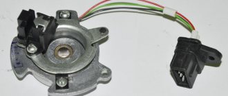
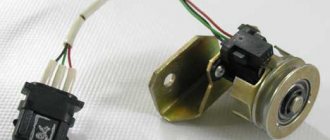
Let's start with basic information: where is the Hall sensor located, what is it, what is it for. A “naked” sensor is a small meter (sensor, detector), almost always black (the color depends on the manufacturer’s preferences), several millimeters in size. Automotive products have a relatively large plastic protective box, a “chip” with a cable with a connection connector.
The phase sensor monitors magnetic fields and their parameters (strength), while producing specified operating algorithms (closing contacts, etc.).
The sensors in question were named after the scientist Hall, who discovered that a potential difference (Hall voltage) occurs when objects with direct currents are placed in a field.
The car current sensor is located in the distributor - a unit for connecting spark plugs; it is hidden by a plastic chip with three wires and a connector for them. On other devices it can be placed anywhere. Usually on printed circuit boards it is a tiny black box, usually with 3, less often - 4 legs. Linear Hall sensors resemble a microcircuit. The product is also identified by its markings; the designations are in reference books of radio components (common ones are S41, 41F, U18, 3144, 44E, 49E).
When current flows in one direction, electrons are deflected in conductors placed perpendicular to the field. Their areas have an uneven density of particles, this is the potential difference recorded by the Hall sensor. It becomes possible to analyze voltage at right angles to current.
There is also a simplified Hall effect sensor, as, for example, in smartphones: only with the function of confirming the presence of magnetic phenomena, the tension is not analyzed. Based on a unit that includes a sensor and a magnetometer, the phone is equipped with a compass option.
How it works
Operating principle of using a Hall sensor:
- When current passes, electrons move linearly through the sensor.
- When exposed to a field, particles with a charge are deflected by the Lorentz force along a curved path.
- Negatively charged elements, also known as electrons, are attracted to one side of the Hall sensor, and positive ones (holes) are attracted to the other.
- The described accumulation in different segments creates different voltages, this is the potential difference. The proportionality of the resulting voltage to the electric current and field strength is direct. These final phenomena are tracked by the sensor; the principle is used to determine the position of the objects being serviced under their control.
Where are they used?
Phase sensors began to be installed in structures about 75 years after their invention, when technologies for creating semiconductor film materials became available.
Typical areas of application of Hall sensors:
- the first area where use began was mechanical engineering, for measuring the angles of camshafts, crankshafts, and detecting sparks on ignition units;
- switches (non-contact type), analyzers for levels of substances, speed of rotation of blades, devices for remote detection of currents;
- scanning magnetic symbols;
- as a replacement for reed switches (circuit breakers with closing contacts via a magnet). In this area, the described devices are the most common due to the large number of devices: microelectronics, equipment from headphones to manipulators, keyboards, in elevators, security equipment (doors, locking elements).
On a smartphone
The hall sensor in a smartphone is used for the following purposes:
- as part of a compass, magnetometer;
- for monitoring the closing/opening of a case with a magnetic latch by tracking field weakening/increasing;
We will describe why a hall sensor is needed in a smartphone on the cover. When the magnet moves away from the detector, there is an impulse to activate the display, when closer, it turns it off. A variety of such cases is a separate type of product, usually called Smart Case. There are also additional functions, their operating principle is as follows: if a cover without windows near the display is used, then the detector turns off the screen when it is closed, and automatically activates when it is opened. If there are windows, switching of contents to the display is initiated. On the visible area there is a clock, etc., on the entire display there is all the information.
Not all smartphones have the described improvement, and manufacturers do not always indicate it in the list of options, so you need to clarify this parameter. But if in the recommended accessories there is a note about those suitable from the Smart Case category, then this option is present.
Varieties
The application of Hall sensors is quite extensive; they are used in many areas of industry. There are two main types of these devices, each of which has its own operating characteristics and areas of use.
Digital
Digital Hall sensors use the principle of interaction of an electromagnetic field with sensitive metal elements (contacts).
The operating principle of the sensor is based on the formation or refraction of an existing signal at the moment of its interaction with a magnetic field. Digital types of devices are divided into 2 main types:
- Unipolar type. The operating principle of such devices is based on operation in the presence of a magnetic field of one polarity, for example, +. If there is no polarity or the element is exposed to a magnet of a different polarity (–), the sensor contacts open and the element turns off the circuit.
- Bipolar. The Edwin Hall bipolar type sensor works by changing the polarity of the magnetic field. For example, with one polarity it works to turn on, and when exposed to the other, it turns off.
The design of a digital Hall sensor is quite simple, and it works due to a small voltage. Hall sensors can be supplemented with an external amplifier, regulator or voltage converter. Additionally, the circuit may contain logical switches.
Hall's digital devices have found their way into the automotive industry. On their basis, for example, speed meters and ignition distributors are produced. Electric bicycles and scooters are now equipped with such devices. Here, the main purpose of the device is to read the number of revolutions of the electric motor rotor per unit of time.
Analog or linear
Linear or analog devices are quite different from digital ones. The operating principle of these elements depends on the magnitude of the impact of the magnetic field on the plate. The greater the impact, the higher the output voltage. In addition, we must not forget that the voltage can only increase up to a certain value.
This is due to the fact that the magnetic field of the plate increases to a certain value, and then the growth of this field and the electrical voltage at the taps stops. Thus, it will not be possible to obtain a higher output voltage by increasing the input voltage or using a more powerful permanent magnet.
Magnetic linear Hall sensor is used in non-contact measuring instruments. For example, current clamps that measure current strength in a non-contact manner are equipped with similar devices. Also, such a linear device can act as a current sensor, meter of rotation angles or vibrations.
Types of Hall sensors
For convenience, we consider the varieties in a table:
Where and why are analog devices used:
- in ABS (anti-lock braking systems);
- motor control (protection, indication);
- devices for detecting power, vibration, ferrous metals in detectors;
- motion monitoring (approach/distance, for example, when parking);
- measurements of flow parameters of substances and structures;
- when adjusting voltage;
- phase sensors located on current clamps (Tong Testers) are involved in measurements.
Digital:
- The Hall sensor is responsible in the car for monitoring the position of the crankshafts for the ignition angle of spark plugs and valves;
- in optics controls the position of the lens;
- determining the placement of seats in the car, the condition of seat belts and airbags;
- wireless communications, mobile computers (smartphones, tablets, laptops);
- in instruments for determining pressure;
- sensors in the parking sensors system, similar devices for fixing approaching/removing distances;
- to analyze flow parameters.
Advantages and disadvantages
Pros:
- universality (they simultaneously determine position, direction, and so on);
- wear resistance. There are no moving parts, they are solid state, rugged devices, providing extreme durability;
- almost complete independence from the need for maintenance;
- The Hall effect current sensor operates under vibrations, in dusty, humid, aggressive conditions, and at high temperatures.
Minuses:
- standard devices have a maximum distance to the measured current of about 10 cm. But it all depends on the magnet: if it is powerful and creates a wide field, then the distance increases;
- a characteristic “disease” is accuracy, since there is a dependence on the magnetic field, and other external similar phenomena can introduce distortions. The same applies to high temperatures, since they change the resistance of conductors, and accordingly, the mobility of charge carriers, but here sensitivity suffers. However, this is rare or the effect is negligible; in general, it does not particularly affect the work.
What is the Hall effect
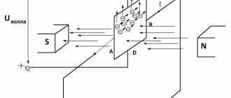
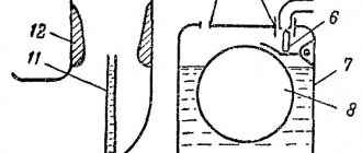
The Hall effect can be considered from the point of view of the movement of charges (charged particles) in a magnetic field. To understand in practice how this happens, connect the battery to the conductor as shown in the figure below. Electric current (i) in this case will begin to flow through the conductor from the positive terminal of the battery to its negative terminal.
But the flow of electrons (e-) in this case will be directed in the opposite direction, that is, from the negative terminal of the battery to its positive terminal. At this point in time, if we measure the voltage (potential difference) at the ends of the conductor (across it) as shown in the figure below, it will be zero.
Now let's create a magnetic field over the conductor as shown in the following figure.
And if at this moment in time we measure the voltage at the ends of the conductor (transverse to the flow of current), then it will be different from zero. This voltage is called the “Hall voltage”, and this phenomenon itself is called the “Hall effect”.
In cars
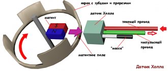
Hall sensors have been installed in vehicles since the 70–80s of the last century, when electric ignition began to be introduced instead of contact ignition. Operating principle: the motor shaft rotates with its impeller passing through the housing slots, which is detected by the detector, which sends a command to the switch, which unlocks the transistor, which supplies voltage to the ignition element with the winding. The latter creates a high voltage for the spark plug.
Design
A box, a “chip” with three contacts, three wires and a connection connector - this is a classic device for automotive Hall effect sensors. Only minor details differ between models. This design, taking into account the nuances of the objects being served, can be considered as a general model.
Hall sensor, device, circuit:
- “ground” (car body), this is “–” or working zero;
- “+”, working serviceable products have about 6 V there;
- contact for transporting the pulse to the switch.
There are the following advantages of current sensors for electronic ignitions:
- there is no constantly burning volumetric contact unit;
- on a candle above 30 kV versus 15 kV, which is much better;
- sensors are installed on brake systems, anti-lock braking systems, and tachometers, so there are important additional advantages: the performance of the internal combustion engine increases, all systems of the car accelerate and work more efficiently. As a result, ease of use and safety increase.
Advantages of Hall sensors
Experts note the following number of advantages of Hall sensors:
- Long service life (for the keyboard - 30 billion keystrokes).
- No moving parts (solid state electronics), which clearly simplifies designs with high vibration and shock requirements.
- Ability to operate at frequencies of magnetic field changes up to 100 kHz.
- Simple combination with logical levels of digital signals.
- Wide range of operating temperatures (from minus 40 to plus 150 degrees Celsius).
- High repeatability of measurements, which makes it easy to calibrate devices based on Hall sensors.
Connecting large electrical loads
The output power of the Hall sensor is very low (10–20 mA), as a result of which it cannot directly control high electrical loads. The problem is solved quite simply: the connection is made by adding an NPN transistor to the device, through which current flows to the output. The specified part acts as a receiver; when it is saturated, it is activated as a switch. The transistor grounds the output contact, thus closing it when the flux density of the set values for “on” increases.
There are various configurations of the transistor switch, but the main thing is that the device provides a 2-cycle output, allowing it to draw the required current to control large loads.
Types of devices
The main task of this device is to determine the magnetic flux intensity. In practice, this is a sensor for determining magnetic field values. There are two types of sensors:
- digital;
- analog.
Unipolar devices turn on when any polarity appears and turn off as it decreases. Digital sensors measure induction and the appearance of the corresponding voltage, that is, the presence or absence of a magnetic field.
The device displays one when the field induction reaches the threshold value. Until this moment, the sensor will show zero. Such a sensor will not be able to detect the presence of a magnetic field with weak induction. In addition, the accuracy of the readings will be affected by the distance to the object being measured.
Current sensor failure
Frequent breakdowns and signs of a Hall sensor malfunction:
- the engine does not start, interruptions in starting;
- unstable idle;
- At high speeds there is jerking (a common sign), the vehicle stalls.
A faulty sensor can short out to the housing, causing ignition problems.
The disadvantage of diagnostics is that the listed symptoms may also be characteristic of failures of other components. The circumstance is partly mitigated by methods that are not too complex, and can be done by users with basic knowledge of technology.
Hall sensor check
There are several options for how to check the Hall sensor and how to analyze the functionality. Choose the most accessible method or one that suits the prevailing conditions - all methods are effective
You need to know what a Hall sensor looks like; checking also means knowing how the pinout works.
Availability simulation
The procedure is the fastest, suitable when there is power to the electric ignition, but there is no spark.
Order:
- The 3-pin block is removed from the distributor.
- Turn on the car ignition.
- Connect (close with a piece of wiring) contacts (terminals) 3 and 2. The first is “–”, the second is “+”, for the signal.
- Move the wires, quickly connecting/disconnecting them from the contacts. There is a spark - the sensor is broken. The high-voltage wire is held near ground.
Checking with a multimeter
Testing the hall sensor with a multimeter is popular; it makes it possible to determine whether the power circuit itself in the product is working properly.
How to check the hall sensor on a VAZ with a tester:
- Convert the tester to voltage analysis (voltmeter) with a range from 0 to 15 V.
- Put the wheel in fourth gear and lift the wheel slightly with a jack (enough to spin it).
- Connect the tester to the sensor, turn the wheel and watch the display.
- Measure the output parameters: a working copy has them in the range of 0.4–11 V.
To check if there is an open circuit, set the tester to the “continuity” mode. One probe to the contact on the chip, the second to the corresponding sensor leg. This method only tests the cable cores, and not the internal structure of the sensor itself. There is no break - a buzzer (if there is such an option) and a jump in numbers close to zero (0.001 and the like); there is a break - 1.
Options for testing circuits with a multimeter and voltmeter:
Replacement with a working copy
You can supply the work item if you have a spare one, or borrow it. If the problem remains, then the old copy is broken, but it is advisable to make sure that it is completely broken and insert it again, having first cleaned the contacts.
Complex method
This procedure for checking a Hall sensor is more complicated than the previous ones, but if you have average knowledge of electrical engineering, it’s easy to apply. The point: check if there is resistance.
To implement it, you need to make a simple knot. Assemble a circuit with an LED, a resistor (1 kOhm), and a Krona battery (9 V). A graphical diagram is enough to understand:
Do-it-yourself Hall sensor with an auxiliary device is checked as follows:
- The diode leg is equipped with resistance (a resistor is soldered), 2 wires are connected to it, preferably longer. Remove the distributor cover, snap off the distributor and plug box. They analyze the electrical circuit: tester probes (a voltmeter will do) to terminals 1 and 3, then ignition. Serviceability - 10–12 V on display;
- similarly, the constructed structure is connected to the same terminals. If the polarity is correct, light will appear; if not, the wires are rearranged;
- We do not disturb the wiring on terminal 1; the end with 3 is thrown onto the free 2;
- turn the camshaft (manually, with the starter): the light blinks - everything is in order, if not, you need to change the Hall meter.
On most vehicles, Hall sensors are tested as closely as possible, as described.
Distinctive features in case of DC malfunction
Malfunctions in the operation of the sensor have various manifestations. Determining them by external signs without opening them is not always possible. Below are some of the most common symptoms of a Hall sensor malfunction:
- the engine does not start or starts poorly;
- unstable operation at idle;
- when driving at high speeds, the car “jerks”;
- The running engine stalls for no apparent reason.
If one or more of the above symptoms appears, the Hall sensor should be checked for defects.
Hall sensor Audi Volkswagen
Replacement
Let's look at the standard procedure for replacing a VAZ hall sensor. The process is simple even for novice car enthusiasts.
The procedure for replacing the Hall sensor:
- Remove the distributor and dismantle its cover.
- Align the marks of the gas distribution mechanism and crankshaft.
- Remove the fasteners with a wrench. In this case, it is recommended to mark and remember (take a photo with a smartphone) the location of the distributor.
- Clamps and stoppers in the housing are also dismantled.
- Remove the shaft from the distributor.
- Disconnect the terminal contacts, unscrew the mounting bolts, and pull out the detector through the slot.
- Connect the sensor correctly - proceed in reverse order.
There is no connection diagram in the car as such, since the sensor has a power cable with a plug, that is, the pinout is already there, and the chip is equipped with “foolproof protection” and keys (protrusions) that make incorrect installation impossible. The detector box has holes for mounting bolts.
In other devices, the Hall effect sensor is soldered according to the location of the legs and contacts under them on the board. If you take a “bare” sensor, however, and if there is a housing, the arrangement of contacts is similar. The required leg for soldering to the board is determined simply, as in the diagram below.
Circuit operation
The device diagram is shown in the following figure.
As you can see, the circuit is very simple. But, unfortunately, novice radio amateurs sometimes confuse the location of the contacts (pinout) of the Hall sensor. Place the hall sensor in front of you so that you are looking at the side of it that has the letters on it, then the first pin on the left will be Vcc (DC voltage), then there will be a ground pin and then a signal pin.
Since, as we already said, we will use interrupts when working with the Hall sensor, so in our circuit its signal pin is connected to pin 2 of the Arduino board, which can be used as an input for the external interrupt INT0. The LED is connected to pin 3 and will light up whenever the Hall sensor detects a magnet. The assembled device on the breadboard will look something like this.
Repair
There is no point in repairing Hall sensors, since the cost of this will exceed its cost, which is in the range of $3–5.
If, out of curiosity, someone wants to do repairs, then you can try to do this for automotive products, but the repair will not concern the very core of the sensor, but the “chip” and the cable: the capacitor often burns out, it and the wires can be resoldered. The cause of the malfunction may lie in soured contacts; they are cleaned.
How to find and order the necessary sensors on Aliexpress at a reasonable price and free shipping
- We register on the site, for which you need to enter your email address, last name and first name, and also create a password. After this, you must confirm your email address, otherwise your account will be blocked.
- Next you need to fill in the delivery address. This is done in your profile and always in Latin characters.
- On the left, next to the “Categories” column, click on the “See all” link.
- Select the “Cars and Motorcycles” category.
- Then click on the link “Car parts”.
- On the left side of the page, select the “Sensors” category.
- In the search line, enter the name of the required sensor, for example, a speed sensor.
- Check the box next to free shipping.
- We choose to sort the results by seller rating.
- We go to the product description page, where we select the quantity, size and color.
- Click on the “Buy Now” link.
- We make payment for the order.