Modern engines with an injection intake system are equipped with controllers (electronic control units - ECUs), which, based on commands from sensors, control the operation of the fuel system according to a given algorithm. The same engine can be equipped with controllers of various types. While performing the same function, most controllers are not compatible with each other, both in terms of operating algorithm and interaction with sensors, and in terms of electrical connections. In particular, the pinout of VAZ 2114 ECUs of different types may be the same, but with differences in the operating algorithm.
The most common types of ECUs are:
- January 7.2
- January 4.0
- Bosch M5.4;
- Bosch M9.7;
- Itelma 5.1
Useful : Where is the mass of the VAZ 2114 ECU (photo and video)
Of the listed January 7.2, electrical wiring is fully compatible with Bosch M7.9.7 and has the same connector. Itelma 5.1 and Bosch M1.5.4 ECUs are also compatible.
The pinout of the VAZ 2114 8-valve ECU is similar to the 16-valve power unit. The differences lie in the operating algorithm (firmware)
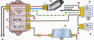
ECU January-4
The January 4 electronic control unit has three connectors, which differ in color and number of contacts. The pinout is as follows:
Pink connector 24 pins:
- A1-A4 – common wire of the on-board network (ground);
- A8, A9 – ignition coil of cylinders 2, 3 and 1, 4;
- A11 – +5V output for powering sensors;
- A12, B8 – positive pole of the battery;
- B2 – tachometer signal;
- B3 – air conditioner clutch;
- B4 – speed signal;
- B5 – adsorber, purge valve control;
- B6 – mass air flow sensor;
- B7 – coolant temperature;
Pink connector 32 pins:
- C1 – positive voltage 12 V from the ignition switch;
- C2 – DD;
- C3 – fuel pump;
- C5 – L-line;
- C12, D8 – control of turning on the injectors of cylinders 2, 3 and 1, 4;
- C16, D16 – mass and signal of the λ-probe (oxygen sensor);
- D10 – air conditioner;
- D16 – DC;
- Blue connector 32 pins:
- C2 – fuel consumption;
- C5, C6 – idle, high and low levels A;
- C7, C8 – idle, high and low levels B;
- C9 – speed sensor;
- C12 – coolant mass;
- C16, D16 – DPKV. High and low levels;
- D1, D12 – TPS signal and mass;
- D2 – fan;
- D4 – k-Line;
- D5 – Check Engine indicator;
Why ELM 327 does not connect to the VAZ 2110 ECU
So, why doesn't ELM327 see the ECU? What should I do so that the device can connect and see the block? Today you can find many different adapters for testing a vehicle on sale. If you buy an ELM327 Bluetooth, most likely you are trying to connect a low-quality device. Or rather, you could have purchased an adapter with an outdated version of the software.
Adapter ELM 327
ELM327 Bluetooth devices with outdated firmware use a different Bluetooth module that allows you to interact with two of the available six protocols. Accordingly, you can synchronize the device with a smartphone, but when you try to connect the device to the control unit, it will inform you that there is no connection with the ECU.
So, for what reasons does the device refuse to connect to the block:
- The adapter itself is of poor quality.
- Problems can be with both the device’s firmware and its hardware. If the main microcircuit is inoperative, it will be impossible to diagnose the engine operation, as well as connect to the computer.
- Bad connection cable. The cable may be broken or inoperative itself. The wrong version of the software is installed on the device, as a result of which it will not be possible to achieve synchronization (the author of the video about testing the device is Rus Radarov)
If you own a device with the correct firmware version 1.5, where all six of the six protocols are present, but the adapter does not connect to the ECU, there is a way out. You can connect to the unit using initialization strings, which allow the device to adapt to the commands of the machine’s motor control unit. In particular, we are talking about initialization lines for diagnostic utilities HobDrive and Torque for vehicles that use non-standard connection protocols.
Bosch M1.5.4
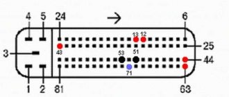
The pinout of the VAZ 2114 Bosch M1.5.4 ECU connector is as follows:
- 1, 20 – Control of ignition coils of cylinders 1, 4 and 2, 3;
- 3 – fuel pump;
- 4, 21, 26, 29 – Contact A, C, B, D IAC;
- 6 – fan;
- 7 – mass air flow sensor;
- 9 – speed sensor;
- 11 – DD;
- 12 – +5V output for powering sensors;
- 13 – L-line;
- 14 – mass of injectors;
- 15, 33 – control of turning on the injectors of cylinders 1, 4 and 2, 3;
- 18 – positive terminal of the battery;
- 19, 24 – mass;
- 22 – Check Engine indicator;
- 25 – air conditioner;
- 27 – positive pole from the ignition switch;
- 30 – mass of sensors;
- 34 – voltage output from the main relay;
- 41 – on air conditioner;
- 43 – tachometer;
- 44 – CO sensor;
- 45 – DTOZH. Terminal B;
- 46 – voltage at the output of the main relay;
- 47 – programming;
- 48, 49 – DPKV. Terminals B, A;
- 53 – TPDZ. Terminal C;
- 54 – fuel consumption level;
- 55 – k-Line.
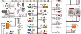
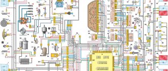
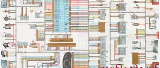
Diagram of the engine control system (ECM) VAZ-2113, 2114 and 2115
Engine control system (ECM) diagram Euro-2 Bosch 7.9.7, January 7.2 VAZ-2113, 2114 and 2115 (2111-1411020-80, 81.82). Engine 1.5 liter 8 valve.
- — controller;
- — block of the ignition system harness to the ABS cabin group harness;
- — diagnostic block;
- — immobilizer warning sensor (APS);
- — immobilizer control unit (APS);
- - ignition coil;
- - spark plug;
- — nozzles;
- — electric fuel pump;
- — block of the ignition system harness to the electric fuel pump harness;
- — block of the fuel level sensor harness to the ignition system harness;
- — block of the ignition system harness to the injector harness;
- — block of the injector harness to the ignition system harness;
- - speed sensor;
- — idle speed regulator;
- — throttle position sensor;
- — coolant temperature sensor;
- — mass air flow sensor;
- — camshaft position sensor (phases);
- — oxygen sensor;
- — crankshaft position sensor;
- - knock sensor;
- — solenoid valve for purge of the adsorber;
- — block of the ignition system harness to the instrument panel harness;
- — controller power supply fuse;
- - ignition relay;
- — ignition relay fuse;
- — fuse for the power supply circuit of the electric fuel pump;
- — electric fuel pump relay;
- — electric fan relay;
- — block of the ignition system harness to the air conditioning harness;
- — pads of the ignition system harness to the front harness;
- — electric cooling system fan;
- — block of the instrument panel harness to the ignition system harness;
- — ignition switch;
- — instrument cluster;
- — on-board control system unit;
- - starter relay;
- — mounting block;
- A - to the “plus” terminal of the battery; B1, B2 - grounding points of the ignition system harness;
2115-3724026-11 — Ignition system harness;
Diagram of the engine control system (ECM) Euro-2 Bosch 7.9.7, January 7.2 VAZ-2113, 2114 and 2115 (21124-1411020-30, 21124-1411020-31.32). 1.6 liter 16 valve engine with individual ignition coils.
- — block of the ignition coil wiring harness to the ignition system harness;
- — block of the ignition system harness to the ignition coil wiring harness;
- — ignition coils;
- — immobilizer warning sensor;
- — immobilizer control unit;
- - spark plug;
- — nozzles;
- — diagnostic block;
- — block of the ignition system harness to the ABS cabin group harness;
- — controller;
- — electric fuel pump;
- — block of the ignition system harness to the fuel level sensor harness;
- — block of the fuel level sensor harness to the ignition system harness;
- — block of the ignition system harness to the injector harness;
- — block of the injector harness to the ignition system harness;
- — block of the ignition system harness to the side door harness;
- - speed sensor;
- — idle speed regulator;
- — throttle position sensor;
- — coolant temperature sensor;
- — mass air flow sensor;
- — oil pressure warning lamp sensor;
- — camshaft position sensor (phases);
- — oxygen sensor;
- — crankshaft position sensor;
- - knock sensor;
- — solenoid valve for purge of the adsorber;
- —
- — coolant temperature indicator sensor;
- — block of the ignition system harness to the instrument panel harness;
- — block of the instrument panel harness to the ignition system harness;
- - ignition relay;
- — ignition relay fuse;
- — fuse for the power supply circuit of the electric fuel pump;
- — electric fuel pump relay;
- — electric fan relay;
- — controller power supply fuse;
- — ignition system harness block to the air conditioner connector;
- — instrument cluster;
- — ignition switch;
- — electric cooling system fan;
- — on-board control system unit;
- — additional starter relay;
- — contacts of the 8-terminal blocks of the instrument panel harness and the front harness;
- — contacts of the 21-terminal blocks of the instrument panel harness and the rear harness;
- - trip computer;
- — diagnostic connector;
- A, E - to the “plus” terminal of the battery; B1 — grounding point of the ignition coil wiring harness; B2 — grounding point of the fuel level sensor harness; B3, B4 - grounding points of the ignition system harness; C - to the starter; D — to the driver's door interior lamp switch;
Diagram of the engine control system (ECM) Euro-3 Bosch 7.9.7+, M73 VAZ-2113, 2114 and 2115 (2111-1411020-30). Engine 1.6 liter 8 valve.
1 - controller; 2 — block of the ignition system harness to the ABS cabin group harness; 3 — diagnostic block; 4 — immobilizer warning sensor (APS); 5 — immobilizer control unit (APS); 6 — ignition coil; 7 — spark plugs; 8 — nozzles; 9 — electric fuel pump; 10 — block of the ignition system harness to the fuel level sensor harness; 11 — block of the fuel level sensor harness to the ignition system harness; 12 — block of the ignition system harness to the injector harness; 13 — injector harness block to the ignition system harness; 14 — speed sensor; 15 — idle speed regulator; 16 — throttle position sensor; 17 — coolant temperature sensor; 18 — mass air flow sensor; 19 — camshaft position sensor (phases); 20 — control oxygen sensor; 21 — crankshaft position sensor; 22 — knock sensor; 23 — solenoid valve for purge of the adsorber; 24 — rough road sensor; 25 — diagnostic oxygen sensor; 26 — block of the ignition system harness to the instrument panel harness; 27 — controller power supply fuse; 28 — ignition relay; 29 — ignition relay fuse; 30 — fuse for the electric fuel pump power supply circuit; 31 — electric fuel pump relay; 32 — electric fan relay; 33 — block of the ignition system harness to the air conditioner harness; 34 — pads of the ignition system harness to the front harness; 35 — electric fan of the cooling system; 36 — block of the instrument panel harness to the ignition system harness; 37 — ignition switch; 38 — instrument cluster; 39 — on-board control system unit; 40 — starter relay; 41 — mounting block;
A - to the “plus” terminal of the battery; B1 — grounding point of the fuel level sensor harness; B2, B3 - grounding points of the ignition system harness;
Diagram of the engine control system (ECM) Euro-3 Bosch 7.9.7+, M73 VAZ-2113, 2114 and 2115 (21124-1411020-10). 1.6 liter 16 valve engine with individual ignition coils and two oxygen sensors.
1 — block of the ignition coil wiring harness to the ignition system harness; 2 — block of the ignition system harness to the ignition coil wiring harness; 3 — ignition coils; 4 — immobilizer warning sensor; 5 — immobilizer control unit; 6 — spark plugs; 7 — nozzles; 8 — diagnostic block; 9 — block of the ignition system harness to the ABS cabin group harness; 10 - controller; 11 — electric fuel pump; 12 — block of the ignition system harness to the fuel level sensor harness; 13 — block of the fuel level sensor harness to the ignition system harness; 14 — block of the ignition system harness to the injector harness; 15 — injector harness block to the ignition system harness; 16 — block of the ignition system harness to the side door harness; 17 — speed sensor; 18 — idle speed regulator; 19 — throttle position sensor; 20 — coolant temperature sensor; 21 — mass air flow sensor; 22 — oil pressure warning lamp sensor; 23 — camshaft position sensor (phases); 24 — control oxygen sensor; 25 — crankshaft position sensor; 26 — knock sensor; 27 — solenoid valve for purge of the adsorber; 28 — diagnostic oxygen sensor; 29 — coolant temperature indicator sensor; 30 — block of the ignition system harness to the instrument panel harness; 31 — block of the instrument panel harness to the ignition system harness; 32 — ignition relay; 33 - ignition relay fuse; 34 — fuse for the electric fuel pump power supply circuit; 35 — electric fuel pump relay; 36 — electric fan relay; 37 — controller power supply fuse; 38 — ignition system harness block to the air conditioner connector; 39 — rough road sensor; 40 — instrument cluster; 41 — ignition switch; 42 — electric fan of the cooling system; 43 — on-board control system unit; 44 - additional starter relay; 45 — contacts of the 8-terminal blocks of the instrument panel harness and the front harness; 46 — contacts of the 21-terminal blocks of the instrument panel harness and the rear harness; 47 — trip computer; 48 — diagnostic connector;
A, E - to the “plus” terminal of the battery; B1 — grounding point of the ignition coil wiring harness; B2, B3 - grounding points of the ignition system harness; B4 — grounding point of the fuel level sensor harness; C - to the starter; D — to the driver's door interior lamp switch;
Source
Appearance and body structure
As for the dimensions, the VAZ-2112 (16 valves) decreased in length by 93 mm. This change occurred in the rear overhang area. But despite all this, the size of the wheelbase did not transform. The body length was 4170 mm. And the height of 1676 mm and width of 1430 mm remained classic for the “tenth” family. The top line on this body very smoothly transforms into a rather small rear overhang and a huge wing. This design allowed the developers to make the car more manageable.
The one hundred percent zinc-coated body of the “10”, which at one time became very popular, is still susceptible to corrosion. Many owners of new cars did not consider it necessary to perform anti-corrosion treatment. The bottom was rapidly rusting to holes.
Installing HIP9011 in January-7.2 classic blocks.
As is known, in the January-7.2 blocks from the classics there are no elements necessary for detecting detonation. Therefore, in February 2015, the idea arose to install the HIP9011 chip (TPIC8101-ATM40) in such blocks with the wiring required for its operation according to a scheme identical to the January-5.1 ECU (new hardware implementation with A5 firmware) and in the j7ls firmware to implement the ability to select a detonation detection algorithm - usual for January 7.2 or standard as January-5.1 (new hardware implementation) which was already implemented a long time ago.
In order to be able to work with HIP9011, the ECU must also have a DS2401 IC with a 4k7 resistor installed (the signal contact is connected to pin P9.3 as in the engineering unit.) This is necessary to determine by the block number the presence or absence of the HIP9011 chip in it.
After installing all parts of the control unit, they are written with a programmer (version v0.005b or higher is required). Then open the ecu.ini file in the malware editor and at the end, in the newly appeared section with the serial number of the block just recorded, add a line saying:
HIP=9011
After this, write the firmware into the block again - when writing the block, if everything is done correctly, the line << HIP 9011 activated >>
Subsequently, the programmer itself will correctly set the flags for working with HIP9011 on the connected unit.
When loading the firmware into the engineering unit from the matrix complex (loading calibrations), you must make sure that the HIP9011 flag in the firmware is cleared (if the engineering unit does not have hip9011), otherwise the program may not work correctly during setup.
Simultaneous installation of elements of the standard detonation detection circuit of the January-7.2 block and HIP9011 is impossible.
Car diagnostics
The appearance of a lit “Check Engine” lamp on the instrument cluster signals the driver that a problem has arisen in the vehicle’s electrical system. You need to understand that checking the vehicle yourself and at a service station can give different results. Special equipment available to professionals will allow more accurate detection of faults.
Self-diagnosis
On a VAZ 2115, the owner can do independent diagnostics and find out what errors are stored in the memory of the engine control unit. The procedure is carried out by calling up fault codes on the dashboard or using a diagnostic adapter.
To carry out diagnostics on the electronic instrument panel, you must perform a certain sequence of actions:
- Sit in the driver's seat of the car, insert the key into the ignition and press the daily mileage reset button located on the instrument cluster.
- Turn the lock key to the ignition switch position.
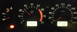
- Release the key, starting the self-diagnosis process. Visually, this will look like turning on the backlight, all signal lamps, possible symbols on the LCD screens and testing the instruments (the arrows will move across the entire scale in both directions).
- Press the key again and release. The second press displays the software version of the instrument cluster on the screen located under the speedometer (inscription like Uer x. x).
- Press the key again, after which the errors in the memory will be displayed on the screen.
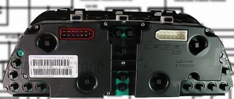
Instrument cluster VAZ 2115, the button is located on the right side of the speedometer
We recommend: VAZ 2114: what to do if the starter turns for a long time and does not start?
The driver can perform self-diagnosis on the electromechanical panel and the “January-4” control unit according to the following sequence:
- Turn off the ignition.
- Open the diagnostic connector cover located on the center console.
- Connect contact B to the negative terminal of the battery (to the body). Contact A, connected to the engine crankcase, is suitable for this.
- Turn on the ignition. The “Check Engine” lamp will flash code 12, which means the diagnosis has begun. The light signals are given as follows - a long flash, then a pause (about 2 seconds), two short flashes, a long pause (about 3 seconds). Signal 12 is sent three times. If there is no signal, the diagnostic system is inactive or faulty. After this, the Check Engine light will flash and list the errors in memory. Each code is repeated three times. If there are no errors in the memory, code 12 will continue to be transmitted.
Electromechanical instrument cluster Pinout of diagnostic connector
To read controller errors, a special K-Line adapter is used, which is connected to the diagnostic connector using a connector. This connector is located on the center console behind a plastic plug (below the cigarette lighter and ashtray). The adapter has a cord with a USB connector at the end that connects to any laptop. A special program for reading and resetting errors must be installed on the device (OpenDiagFree version 1.4 or 1.6).
The procedure for reading errors is quite simple, you need to:
- Check the level of process fluids.
- Open the connector cover and turn on the ignition.
- Connect the adapter or scanner to the diagnostic socket.
- Launch the software on the laptop.
- View available errors in the program dialog box.
- Decrypt the codes using the program interface or decryption table.
- Eliminate the causes of malfunctions and re-diagnostics.
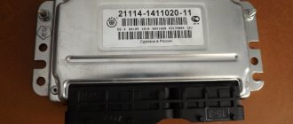
Description of "brains"
2114 is an on-board vehicle computer designed to control basic vehicle systems. The parameters of the control module affect both the functionality of certain regulators and the operation of the engine as a whole.
That is, the importance of this system cannot be denied
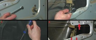
Controller Location
In VAZ 2114 and VAZ 2115 cars, the control module is installed under the center console of the car, in particular, in the middle, behind the panel with the radio. To get to the controller, you need to unscrew the latches on the side frame of the console. As for the connection, in Samar modifications with a one and a half liter engine, the mass of the ECU is taken from the power unit housing, from the fastening of the plugs located to the right of the cylinder head.
Location of the ECU in the Chetyrka
In cars equipped with 1.6- and 1.5-liter engines with a new type of ECU, the mass is taken from the welded stud. The pin itself is fixed on the metal body of the control panel near the floor tunnel, not far from the ashtray. During production, VAZ engineers, as a rule, do not securely fix this pin, so over time it can become loose, which will lead to the inoperability of some devices.
Design and principle of operation
The control unit of the electronic system operates in accordance with the indicators received from the sensors:
- speed;
- detonation;
- lambda probe;
- fuel injection phases;
- crankshaft position;
- throttle position;
- air flow meter;
- antifreeze temperature.
In accordance with the data received from these controllers, the control module controls the following systems:
- ignition;
- adsorber;
- injectors, as well as a fuel pump;
- ventilation and heating system;
- programs for diagnosing vehicle performance;
- idle speed regulator (video author - Evgeniy Vekhter).
As for the device, the control module structurally consists of the following components:
- RAM or random access memory. This module contains basic data about recently identified errors detected by the electronic system in the operation of various components. When the driver turns off the ignition, the RAM unit is updated, causing this data to disappear.
- PROM is the main element of the system; it contains the firmware of the control module. It should be noted that this memory block contains all the necessary data on the calibration of the “four” systems along with the general engine control algorithm. Unlike RAM, EPROM is a permanent memory, so the data stored in it is retained even after the ignition is turned off. If necessary, this module can be reconfigured, that is, reprogrammed, which can lead to improved power as well as vehicle dynamics.
- ERPZU - the primary function of this module is to protect the car. The EEPROM memory contains information from the anti-theft installation - passwords, as well as encoding of the main parameters. Starting the engine will only be possible if the EEPROM successfully checks with the data contained in the immobilizer memory.
Typical malfunctions: their symptoms and causes
What are the signs that indicate a faulty ECU:
- there are no control signals coming from actuators (IAC, flow meter, various sensors, etc.);
- there is no signal for interaction with the ignition system, fuel pump, injectors and other elements;
- when connecting a diagnostic tester, there will also be no connection with the electronic system;
- Burnt contacts and mechanical damage to the device may also be a sign.
What reasons contribute to the failure of the control device:
- electrical circuit shorted or broken;
- improper electrical repairs, during which errors were made, in particular, we are talking about installing or repairing an anti-theft system;
- lighting a dead battery from a car with the engine running;
- a breakdown of the unit can be caused by incorrect connection of the battery terminals - plus instead of minus and vice versa;
- disconnecting the battery contacts when the engine is running;
- moisture on the electronic system module board;
- mechanical damage to the device as a result of an accident (the author of the video about repairing the control module in a garage is the Auto Practice channel).