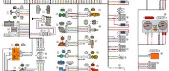
Diagram of the engine control system (ECM) VAZ-2113, 2114 and 2115
Engine control system (ECM) diagram Euro-2 Bosch 7.9.7, January 7.2 VAZ-2113, 2114 and 2115 (2111-1411020-80, 81.82). Engine 1.5 liter 8 valve.
- — controller;
- — block of the ignition system harness to the ABS cabin group harness;
- — diagnostic block;
- — immobilizer warning sensor (APS);
- — immobilizer control unit (APS);
- - ignition coil;
- - spark plug;
- — nozzles;
- — electric fuel pump;
- — block of the ignition system harness to the electric fuel pump harness;
- — block of the fuel level sensor harness to the ignition system harness;
- — block of the ignition system harness to the injector harness;
- — block of the injector harness to the ignition system harness;
- - speed sensor;
- — idle speed regulator;
- — throttle position sensor;
- — coolant temperature sensor;
- — mass air flow sensor;
- — camshaft position sensor (phases);
- — oxygen sensor;
- — crankshaft position sensor;
- - knock sensor;
- — solenoid valve for purge of the adsorber;
- — block of the ignition system harness to the instrument panel harness;
- — controller power supply fuse;
- - ignition relay;
- — ignition relay fuse;
- — fuse for the power supply circuit of the electric fuel pump;
- — electric fuel pump relay;
- — electric fan relay;
- — block of the ignition system harness to the air conditioning harness;
- — pads of the ignition system harness to the front harness;
- — electric cooling system fan;
- — block of the instrument panel harness to the ignition system harness;
- — ignition switch;
- — instrument cluster;
- — on-board control system unit;
- - starter relay;
- — mounting block;
- A - to the “plus” terminal of the battery; B1, B2 - grounding points of the ignition system harness; 2115-3724026-11 — Ignition system harness;
Diagram of the engine control system (ECM) Euro-2 Bosch 7.9.7, January 7.2 VAZ-2113, 2114 and 2115 (21124-1411020-30, 21124-1411020-31.32). 1.6 liter 16 valve engine with individual ignition coils.
- — block of the ignition coil wiring harness to the ignition system harness;
- — block of the ignition system harness to the ignition coil wiring harness;
- — ignition coils;
- — immobilizer warning sensor;
- — immobilizer control unit;
- - spark plug;
- — nozzles;
- — diagnostic block;
- — block of the ignition system harness to the ABS cabin group harness;
- — controller;
- — electric fuel pump;
- — block of the ignition system harness to the fuel level sensor harness;
- — block of the fuel level sensor harness to the ignition system harness;
- — block of the ignition system harness to the injector harness;
- — block of the injector harness to the ignition system harness;
- — block of the ignition system harness to the side door harness;
- - speed sensor;
- — idle speed regulator;
- — throttle position sensor;
- — coolant temperature sensor;
- — mass air flow sensor;
- — oil pressure warning lamp sensor;
- — camshaft position sensor (phases);
- — oxygen sensor;
- — crankshaft position sensor;
- - knock sensor;
- — solenoid valve for purge of the adsorber;
- —
- — coolant temperature indicator sensor;
- — block of the ignition system harness to the instrument panel harness;
- — block of the instrument panel harness to the ignition system harness;
- - ignition relay;
- — ignition relay fuse;
- — fuse for the power supply circuit of the electric fuel pump;
- — electric fuel pump relay;
- — electric fan relay;
- — controller power supply fuse;
- — ignition system harness block to the air conditioner connector;
- — instrument cluster;
- — ignition switch;
- — electric cooling system fan;
- — on-board control system unit;
- — additional starter relay;
- — contacts of the 8-terminal blocks of the instrument panel harness and the front harness;
- — contacts of the 21-terminal blocks of the instrument panel harness and the rear harness;
- - trip computer;
- — diagnostic connector;
- A, E - to the “plus” terminal of the battery; B1 — grounding point of the ignition coil wiring harness; B2 — grounding point of the fuel level sensor harness; B3, B4 - grounding points of the ignition system harness; C - to the starter; D — to the driver's door interior lamp switch;
Diagram of the engine control system (ECM) Euro-3 Bosch 7.9.7+, M73 VAZ-2113, 2114 and 2115 (2111-1411020-30). Engine 1.6 liter 8 valve.
1 - controller; 2 — block of the ignition system harness to the ABS cabin group harness; 3 — diagnostic block; 4 — immobilizer warning sensor (APS); 5 — immobilizer control unit (APS); 6 — ignition coil; 7 — spark plugs; 8 — nozzles; 9 — electric fuel pump; 10 — block of the ignition system harness to the fuel level sensor harness; 11 — block of the fuel level sensor harness to the ignition system harness; 12 — block of the ignition system harness to the injector harness; 13 — injector harness block to the ignition system harness; 14 — speed sensor; 15 — idle speed regulator; 16 — throttle position sensor; 17 — coolant temperature sensor; 18 — mass air flow sensor; 19 — camshaft position sensor (phases); 20 — control oxygen sensor; 21 — crankshaft position sensor; 22 — knock sensor; 23 — solenoid valve for purge of the adsorber; 24 — rough road sensor; 25 — diagnostic oxygen sensor; 26 — block of the ignition system harness to the instrument panel harness; 27 — controller power supply fuse; 28 — ignition relay; 29 — ignition relay fuse; 30 — fuse for the electric fuel pump power supply circuit; 31 — electric fuel pump relay; 32 — electric fan relay; 33 — block of the ignition system harness to the air conditioner harness; 34 — pads of the ignition system harness to the front harness; 35 — electric fan of the cooling system; 36 — block of the instrument panel harness to the ignition system harness; 37 — ignition switch; 38 — instrument cluster; 39 — on-board control system unit; 40 — starter relay; 41 — mounting block;
A - to the “plus” terminal of the battery; B1 — grounding point of the fuel level sensor harness; B2, B3 - grounding points of the ignition system harness;
Diagram of the engine control system (ECM) Euro-3 Bosch 7.9.7+, M73 VAZ-2113, 2114 and 2115 (21124-1411020-10). 1.6 liter 16 valve engine with individual ignition coils and two oxygen sensors.
1 — block of the ignition coil wiring harness to the ignition system harness; 2 — block of the ignition system harness to the ignition coil wiring harness; 3 — ignition coils; 4 — immobilizer warning sensor; 5 — immobilizer control unit; 6 — spark plugs; 7 — nozzles; 8 — diagnostic block; 9 — block of the ignition system harness to the ABS cabin group harness; 10 - controller; 11 — electric fuel pump; 12 — block of the ignition system harness to the fuel level sensor harness; 13 — block of the fuel level sensor harness to the ignition system harness; 14 — block of the ignition system harness to the injector harness; 15 — injector harness block to the ignition system harness; 16 — block of the ignition system harness to the side door harness; 17 — speed sensor; 18 — idle speed regulator; 19 — throttle position sensor; 20 — coolant temperature sensor; 21 — mass air flow sensor; 22 — oil pressure warning lamp sensor; 23 — camshaft position sensor (phases); 24 — control oxygen sensor; 25 — crankshaft position sensor; 26 — knock sensor; 27 — solenoid valve for purge of the adsorber; 28 — diagnostic oxygen sensor; 29 — coolant temperature indicator sensor; 30 — block of the ignition system harness to the instrument panel harness; 31 — block of the instrument panel harness to the ignition system harness; 32 — ignition relay; 33 - ignition relay fuse; 34 — fuse for the electric fuel pump power supply circuit; 35 — electric fuel pump relay; 36 — electric fan relay; 37 — controller power supply fuse; 38 — ignition system harness block to the air conditioner connector; 39 — rough road sensor; 40 — instrument cluster; 41 — ignition switch; 42 — electric fan of the cooling system; 43 — on-board control system unit; 44 - additional starter relay; 45 — contacts of the 8-terminal blocks of the instrument panel harness and the front harness; 46 — contacts of the 21-terminal blocks of the instrument panel harness and the rear harness; 47 — trip computer; 48 — diagnostic connector;
A, E - to the “plus” terminal of the battery; B1 — grounding point of the ignition coil wiring harness; B2, B3 - grounding points of the ignition system harness; B4 — grounding point of the fuel level sensor harness; C - to the starter; D — to the driver's door interior lamp switch;
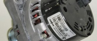
Siemens Deka injectors
There is no certainty with Siemens injectors, since the plant can install injectors of different markings on the same engine. However, there is a clear difference between the injectors for eight-valve and 16-valve engines.
They are marked as VAZ20734 (orange markings) and 20735 (blue markings). On eight-valve engines, a Siemens 6393 nozzle with a thick torch can be used. Its productivity is 1.662 mg/sec, and its operating pressure is 3 atm. Each of these injectors can be installed on a VAZ-2114 engine.
Injector Siemens-vaz20734 Injector Siemens-vaz20735
Schematic diagram (pinout) of connecting the front wiring harness on the Priora
The front part of the vehicle's electrical circuit is designed to supply voltage to the primary and auxiliary power circuits of the vehicle's on-board systems. The decoding of contact group chips is as follows:
- 1 – starter power supply;
- 2 – battery;
- 3 – charge supply from the generator;
- 4 – connecting block for the bundle (1 – 3);
- 5-7 – power supply to the device;
- 8 – engine compartment lighting lamp;
- 9-10 – head light;
- 11 – brake expansion tank level indicator;
- 12 – outside temperature;
- 13 – washer drive;
- 14 – external indication of reverse gear;
- 15 – cooling system fan;
- 16 – stove reducer;
- 17 – reserve resistor;
- 18 – wiper drive;
- 19 – interior relay and fuse module;
- 20 – stove motor;
- 21 – sound alarm indicator;
- 22 – horn power supply;
- A1/2, B1/2 – mass.
VAZ 2170 ECM harness connection diagram
This part is organized to supply power to the main instruments and engine control system of the Lada Priora. From here, voltage is supplied to the main components, units of the vehicle’s power plant, as well as control sensors and ECUs. The standard electrical circuit connection system (pinout) looks like this:
- 1 – ECU power supply;
- 2 – main block of the electronic system to the dashboard;
- 3 – distribution board;
- 4 – speedometer;
- 5 – road surface roughness sensor;
- 6 – indication of pressure in the engine crankcase;
- 7 – TPS;
- 8 – DTOZH;
- 9 – indication of antifreeze temperature sensor;
- 10 – mass air flow sensor;
- 11 – control XX;
- 12 – main relay of the fuel pump;
- 13 – VT circuit fuse;
- 14 – relay BZ;
- 15 – fuse of the above circuit;
- 16 – ECU fusible link;
- 17 – DPKV;
- 18 – power supply for mass air flow sensor;
- 19 – phase distribution;
- 20 – mixture detonation sensor;
- 21 – EMC for purging the adsorber;
- 22 – diagnostics of the air flow sensor;
- 23 – power supply to the ignition coil;
- 24 – supply voltage to spark plugs;
- 25 – power supply to fuel injectors;
- 26 – terminal from the ignition coils to the ECM;
- 27 – feedback from 26;
- 28 – ECM connector to the injection system;
- 29 – response to the previous output;
- A – phase on the battery;
- B1/2 – ignition mass;
- C1 – mass from short circuit.
Let's sum it up
As you can see, by analogy with various foreign cars, VAZ injection engines of different generations are also equipped with controllers of various types. Early versions have simple solutions that are responsible for simple mixture formation and work with a small number of sensors.
At the same time, more modern control units are distinguished by support for distributed injection, more flexible control of the ignition system, as well as the ability to interact with oxygen sensors, etc.
Only after all the nuances have been taken into account can you expect that the engine under ECU control will operate correctly and without failures, and the owner himself will receive stable operation of the power unit and systems, environmental friendliness and maximum efficiency from the engine in different operating modes of the car’s engine.
Interpretation of the symbols for the rear wiring harness of the VAZ Priora
The rear part of the electrical wiring chain is responsible for the vehicle's lighting and peripheral systems. This includes lights, locks and windows. The pinout of tips and terminals looks like this:
- 1 – dashboard response;
- 2 – power supply for the door behind the driver;
- 3/28 – power supply for the front passenger panel equipment;
- 4 – maintenance of power windows and door locks;
- 5-6 turn signals;
- 7 – interior lighting;
- 8 – handbrake indication switch;
- 9-10 – aft dimensions;
- 11 – temperature inside the car;
- 12-15 – circuit breakers for lighting the interior of the machine;
- 16/17 – power supply to the devices of the aft right and front left doors, respectively;
- 18/19 – voltage to the rear right and left speakers, respectively;
- 20 – cigarette lighter power core;
- 21 – EBN;
- 22 – contact group of the cargo compartment lighting circuit breaker;
- 23 – heated rear windshield;
- 24 – luggage compartment lighting lamp;
- 25 – additional stop;
- 26 – power line to the electric lock of the luggage compartment lid;
- 27 – power supply for rear number plate illumination;
- A1-4 – mass;
- ХР1/3 – electrical package power controller.
Pinout for rear license plate illumination of VAZ 2170
The small harness, located in the luggage compartment, has only three terminals:
- 1 – power supply to the stern license plate lights;
- 2-3 – license plate lighting lamps;
- 4 – trunk lid lock motor.
Pinout for the driver's door of the Priora
The harness is routed to supply power to the driver's door equipment. There is an output to the key panel installed in the armrest. There are six elements in total:
- 1 – additional terminal to the rear of the machine;
- 2 – line to the left fuse;
- 3 – electric window drive;
- 4 – armrest control module;
- 5 – door lock drive;
- 6 – rear view mirror control chip.
Front Passenger Door Wiring Harness
The unit duplicates the voltage supply from the center console to the passenger keypad located on the right side of the car. There are only seven connectors here:
- 1 – continuation of the main highway to the rear;
- 2 – terminal of the line to the right front speaker;
- 3 – window lift drive;
- 4 – electric window lift button;
- 5 – door lock drive;
- 6 – control of the position of the rear view mirror, as well as heated glass;
- 7 – continuation of the highway to the rear.
Rear door harnesses
The rear door wiring diagram has only two terminals. In this case, the side of the car is not of fundamental importance:
- 1 – continuation of the highway;
- 2 – locking drive.
Serial firmware VAZ Bosch M7.9.7+
Bosch M7.9.7 new hardware implementation (M7.9.7+) Software ID VAZ number Note B103EQ12 2111 – 1411020-80 1 Serial version for new hardware implementation, E2 standards B103ER12 2111 – 1411020-80 2 Serial version for new hardware implementation, E2 standards B104DQ17 21114 – 1411020-30 1 Serial version for new hardware implementation, E2 standards B104DR17 21114 – 1411020-30 2 Serial version for new hardware implementation, E2 standards B105DQ09 21124 – 1411020-30 1 Serial version for new hardware implementation, E2 B1 standards 05DR09 21124 – 1411020-30 2 Serial version for new hardware implementation, standard E2 B105DR10 21124 – 1411020-30 3 Serial version for new hardware implementation
ECU made in France, E2 standards B108DQ09 21124 – 1411020-10 1 Serial version for new hardware implementation, E3 standards B108DR09 21124 – 1411020-10 2 Serial version for new hardware implementation, E3 standards B109DR02 21124 – 1411020-20 3 Serial version for new device noah implementations, E3 standards B119DQ01 21114 – 1411020-20 1 Euro‑3 serial version for new hardware implementation, XC05_M7A1, E3 standards B119DR02 21114 – 1411020-20 Bogdan, serial version, software XC06_M7A1, E4 standards B120EQ16 21214 – 1411020-30 1 Serial version for new hardware implementation, E2 standards B120ER16 21214 – 1411020-30 2 Serial version for new hardware implementation, E2 standards B120ER19 21214 – 1411020-30 3 Serial version for new hardware implementation, E2 standards B122HR01 21230 – 1411020-90 1 Serial version for new hardware implementation on Niva - Chevrolet vehicles, E2 standards Attention! The firmware has a problem with turning on the fans B122HR91 21230 – 1411020-90 2 Serial version for the new hardware implementation on Niva – Chevrolet, E2 standards 22XC052S 21230 – 1411020 “Clone” B122HR01, E4 standards 22YC041S 21230 – 1411020- 40 Niva – Chevrolet, E4 standards B114ER18 21214 – 1411020-20 Serial version for the new hardware implementation on the Niva 21214 car, E3 standards B114ER17 21214 – 1411020-20 Serial version for the new hardware implementation on the Niva 21214 car. Version from the export car, E3 standards B126ES01 2104 – 1411020-10 1 Serial version for the new hardware implementation for 1.45 l classic cars, E2 standards B126ER02 2104 – 1411020-10 2 Serial version for the new hardware implementation for 1.45 l classic cars, norms E2 B102CQ05 Kalina 1 Serial for Kalina, standards E3 B102CR06 Kalina 2 Serial for Kalina, standards E3 B101CR01 11183 – 1411020-02 1 Serial for Kalina, standards E2 B101CR02 11183 – 1411020-02 2 Serial for Kalina, standards E2 B104CR 01 21114 – 1411020- 40 Viburnum, paper nameplate, E3 standards B104CR02 21114 – 1411020-40 Viburnum, differences from CR01 only in fan temperature thresholds, E3 standards B103CU03 21114 – 1411020-40 Viburnum, paper nameplate, without DND, E3 standards B173DR01 21126 – 141102 0-10 1 Serial for Priora, standards E3 B174DR03 21126 – 1411020-00 2 Serial for Priora, standards E4* B174DR04 21126 – 1411020-00 3 Serial for Priora, equipped with power steering, standards E4* B174DT05 21126 – 1411020-30 4 Serial for Pria yell, norms E4* B174DT06 21126 – 1411020-30 5 Serial for Priora, standards E4* B174DT07 21126 – 1411020-00 6 Serial for Priora, standards E4* B173СR03 11194 – 1411020 1 Serial for Kalina 1.4 l., standards E3 B174 CR03 11194 – 1411020 -10 2 Serial version for Kalina 1.4 l., E3 standards B174СT04 11194 – 1411020-10 3 Serial version for Kalina 1.4 l., E3 standards 22YB072S 2123 – 1411020-30 1 Serial version Euro‑3 for new hardware implementation on a /m Niva - Chevrolet, E3 standards OPP firmware** Bosch M7.9.7+ B120ER1733XCO305B133ER17 21214 – 1411020-30 OPP firmware from Niva 1.8 (in identifiers 1.7)
Without phase sensor. 33XCO305 and B133ER17 are “clones” of B120ER17, E2 standards B121ER17 21214 – 1411020-10 Firmware for STC VAZ OPP for the long Niva, E3 standards B11KSS01 11196 – 1411020 STC VAZ OPP firmware for Kalina Sport 1, 6 16V, standard E3 B13KSS02 21126 – 1411020-60 Firmware for OPP STC VAZ for Kalina Sport 1.6 16V. There are two options in the archive with different KS and identifiers, E3 standards
* Toxicity standards are indicated in accordance with IP VAZ ** OPP - Experimental Industrial Enterprise, a subsidiary of AvtoVAZ. Attention! Some firmware for Bosch M7.9.7 can be presented in two forms, in the compressed “Combiloader” format and regular bin files (with the prefix “c”)
Electrical diagram of the dashboard (Torpedo) VAZ-2170 Priora
Part of the on-board network is designed to power the main group of vehicle equipment. The control and display elements of the instrument panel are concentrated here. The wiring supplies power to loaded parts and critical components:
- 1-3 – contact group of the front harness;
- 4 – supply voltage to the aft connector;
- 5 – power supply from the fuse panel;
- 6 – contact group of stops;
- 7 – instrument panel indication;
- 8 – control of illuminators;
- 9 – contact group of emergency airbags;
- 10 – horn;
- 11 – power supply of the diagnostic unit;
- 12 – on-board PC control;
- 13 – ignition coil controller;
- 14 and 15 – supply voltage to the EUR control unit;
- 16 – control of power window equipment;
- 17 – alarm relay;
- 18 – wiper regulator;
- 19 – air flow distributor for the ventilation system;
- 20 – stove;
- 21 – heater drive;
- 22 – heated rear wind window;
- 23 – onboard clock;
- 24-25 – radio connection;
- 26 – emergency warning button;
- 27 – glove compartment lighting;
- 28 – control button for the glove box illumination;
- 29 – bundle of wiring for ignition;
- 30 – to the emergency airbag control board.
Pinout of the instrument panel VAZ 2170 Priora
The layout of the instrument panel is made in a simplified version to facilitate the replacement and installation of replacement parts. The decoding of the wiring connections at the factory terminals looks like this:
- 1 – EUR;
- 2 – emergency signal control;
- 3 – oil pressure sensor;
- 4 – indicator light for turning on the hand brake;
- 5 – immobilizer control unit;
- 6 – control unit for airbags;
- 7 – external lighting of the car;
- 8-9 – direction indicators;
- 10 – control of the combustible mixture injection system;
- 11 – disabling the front passenger SB;
- 12 – indication of seat belt buckles;
- 13 – operation of the brake system;
- 14 – reset button of the steering column switch;
- 15 – indication of the expansion tank of the brake system;
- 16 – ABS control unit;
- 17 – headlight high beam position switch;
- 18 – dashboard lighting;
- 19 – mass;
- 20 – receiving power from the battery terminal;
- 21 – ignition switch connector;
- 22 – fuel consumption sensor;
- 23-24 – BC mode switch;
- 25-26 – temperature sensor “overboard”;
- 27 – remaining fuel in the tank;
- 28 – speedometer;
- 29 – antifreeze temperature indication;
- 30 – tachometer;
- 31 – diagnostic terminal;
- 32 – power supply from generator (L).
Tuning and replacement of the center console on Lada Priora and Kalina
Modern versions of cars are supplied to the market with a restyled version of the tidy. Here, a relatively old generation, navigation and a liquid crystal display appeared. Installing an updated shield requires the following steps.
Selecting the required version
There are only two types of updated designs with and without a CAN bus. The nuance is that the versions are completely identical in appearance. In order to find out which variety is suitable, you need to check the production date of the car. Machines manufactured before 06, 2012 are not equipped with this technology. The article numbers for the new devices with navigation are as follows:
- 2170-3801010-50 without CAN;
- 2170-3801010-60 with CAN.
Also in the kit you need to purchase a navigation antenna and a steering column switch of the appropriate design.
Installation nuances
For Lada Kalina versions, all devices are not equipped with a CAN module. Also the old generation of Priora. Here the installation is carried out without modifications or nuances - just snap out the old panel, remove the terminals, and mount the new set on the stock fasteners. Next, you need to install a navigation antenna on the roof and connect it to the appropriate connector. The second case is when an old panel with a CAN unit, but without navigation, is replaced with an analogue one. Here it is necessary to rearrange the contact connectors of the standard wiring from positions 10-11 to sockets No. 28-29. In case of incorrect operation of the devices, the replaced wires are swapped with each other. After the repair is completed, the counters should reset to zero.
Connector pinout January 7 2
I would like to immediately convey a special greeting to the designer of AvtoVAZ, who came up with this arrangement of this block. In my opinion, I can't think of a worse place. See for yourself.
The ECU is located under the glove compartment under the passenger's feet and hidden under the upholstery. The upholstery is attached to the body on the right with a self-tapping screw.
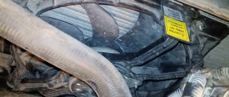
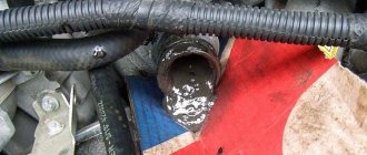
- If your interior heater (radiator) leaks, the antifreeze will go straight to the control unit, causing almost 100% failure. Even though the Lada Granta is initially equipped with a good quality imported Visteon radiator.
- As you correctly noted, water can get in from under the hood. The rubber plugs on the Lada Granta are not of very good quality, so when they dry out, water will flow onto the controller. To prevent this from happening, check the condition of the rubber plug.
- If the drainage hole (which is shown in the video below) becomes clogged, water may flow into the cabin.
Pinout of the lighting control unit on Priora
The module is connected to the vehicle’s on-board network via chip No. 1118-3724500. The standard terminal pinout on a VAZ 2170 looks like this:
- G56b – for the gearbox for adjusting head lighting devices;
- 58b – output from lighting and instruments;
- 31 – neutral earth cable;
- Xz – 12 volts from pin 15 of the ignition switch;
- 56 – relay switch for high and low headlight modes;
- 1, 3 – connection of fog lights;
- 2, 4 – sending a signal to the controller;
- 58 – dimensions;
- 30 – power supply from the ignition switch design.
The standard electrical connection diagram (pinout) for the VAZ 2170 Priora has its shortcomings and strengths. However, thanks to the simple design, you can eliminate defects yourself, without the involvement of service station specialists.
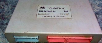
Location of the Lada Granta ECU
We can talk for a long time about how important the correct operation of the electronic control unit (ECU) is. The functioning of the heart of your car depends on it: from increased fuel consumption to the fact that the car may stall as a result of incorrect operation of the controller.
I would like to immediately convey a special greeting to the designer of AvtoVAZ, who came up with this arrangement of this block. In my opinion, I can't think of a worse place. See for yourself.
The ECU is located under the glove compartment under the passenger's feet and hidden under the upholstery. The upholstery is attached to the body on the right with a self-tapping screw.
- If your interior heater (radiator) leaks, the antifreeze will go straight to the control unit, causing almost 100% failure. Even though the Lada Granta is initially equipped with a good quality imported Visteon radiator.
- As you correctly noted, water can get in from under the hood. The rubber plugs on the Lada Granta are not of very good quality, so when they dry out, water will flow onto the controller. To prevent this from happening, check the condition of the rubber plug.
- If the drainage hole (which is shown in the video below) becomes clogged, water may flow into the cabin.
In general, as you understand, the location of the ECU on the Grant is not the best! So we just need to face it.