At first glance, one might assume that the speed sensor is a simple analyzer, and if it breaks, you should not worry. But, despite its initial inconspicuousness, the speed sensor performs an important function in normalizing engine function.
The speed sensor transmits a signal to the vehicle's electronic control unit with speed indicators. The control unit receives the signal and converts it for transmission to actuators. Thus, the idle speed of the car is adjusted and the required saturation of the fuel mixture is adjusted before it is supplied to the engine.
Even after passing a short distance, the sensor transmits a huge number of impulses to fully optimize the most important vehicle systems. Thanks to the average readings, the car's control devices receive speed parameters visible to the driver.
Of course, one of the most productive and important functions in the operation of a speed sensor is the regulation and saving of fuel mixture consumption. When a certain speed is reached (depending on the characteristics of the vehicle, sensor parameters and ECU settings), the throttle controller sends a signal to stop supplying the fuel mixture. The control device, receiving the signal, prevents the supply of fuel to the car engine, thereby reducing unnecessary consumption.
Checking the speed sensor.
Diagnostics of speed analyzer faults includes:
- Stopping the operation of the car’s engine if it behaves unusually at idle. Also, you should not use the car if the speedometer begins to show incorrect speed parameters.
- Next, the speed sensor is diagnosed using the vehicle's on-board unit, or using a special diagnostic device that determines the fault code.
When diagnosing with a specialized device, or if the standard testing system independently detects an error, it is necessary to find correspondence to the numerical values in the manufacturer’s instructions.
Causes of malfunction of the speed sensor.
If the speed readings on the dashboard do not correspond to reality, this does not mean that the speed sensor has failed. Although the price of the sensor is relatively low and replacing it is quite simple, you should not do this until it is fully confirmed that it is at fault for the malfunction.
The reasons for the failure of the speed sensor may be:
- The presence of traces of oil or deposits of dust and dirt on the surface of the device. Due to contamination of the sensor, the signal is distorted and incorrect speed readings are displayed on the dashboard. In this case, the problem can be solved quite simply - you need to check the surface for dirt and clean it.
- Violation of the tightness of the conductors, or loss of communication with the ECU. Violation of the sensor structure and its subsequent failure, or extraneous mechanical influences on the speedometer conductor. Thus, the cable may move unevenly or touch the external protection, thereby complicating the move and dulling the signal. In this regard, the correct functioning of the car speed sensor is disrupted. Also, the analyzer will not work correctly with increased cable vibrations.
How to diagnose a problem
There are only 3 ways to check the tens speed sensor. One of them involves the use of a control lamp, the other two are based on a circuit.
But before moving on to any of them, make sure that there is grounding and voltage on the contacts; to do this, disconnect the electrical connector from the sensor by simply squeezing the “antennae” and removing the chip, and ring each of them. One of the contacts should show a voltage of 12V.
If everything is fine with the power supply, proceed directly to the diagnosis itself.
Method No. 1 - carried out according to the above scheme without removing the sensor from the car. Jack up the front wheels. Using regular wires (if you have an assistant) or with alligator clips (if you don’t have an assistant), connect the voltmeter to the speed sensor, not forgetting to supply current to it. Place the gearbox in 5th gear and rotate the wheel. If everything is in order with the sensor, in response to these actions you will see changes in the voltage of the pulse contact - between the output and ground - the higher the speed, the greater the voltage. The range of changes is 0.5-10V.
Method No. 2 - carried out according to the above diagram on a sensor removed from the car. Remove the speed sensor (how to do this will be described in detail below in the instructions for replacing it). Using wires, again repeat the above diagram. Take a tube, pliers or any other handy item that allows you to rotate the sensor axis (the main thing here is not to forget about safety precautions), and rotate the sensor around its axis. The resulting multimeter readings (from 0.5V to 10V) will indicate that everything is in order with the sensor.
Method number 3 – “light bulb test”. Applies to the speed sensor without removing it from the vehicle. Using a jack, raise the drive wheels on the ground. According to the diagram below, connect a light bulb to the element being diagnosed. Place the gearshift lever in 5th gear and rotate the wheel. The light should blink. If this does not happen (if there is voltage in the network, of course), the sensor should be replaced.
We check the speed sensor on the VAZ 2110 with our own hands.
Diagnostics of the device is carried out in several stages and in full compliance with all safety requirements. Check sequence.
- Using a lift, we set the front of the car to a height.
- We disconnect the conductor from the analyzer and attach it to the measuring device. A digital voltage meter is best.
- First of all, we check the serviceability of the element by the presence of current in the circuit and a short circuit. Next, it is necessary to analyze the device by driving the machine wheel (by hand). The device values should change in direct proportion to the wheel speed.
- We dismantle the speed analyzer.
- We connect the device for testing to the outputs of the analyzer.
- We monitor the readings of the device when moving the working element of the sensor.
Thus, we should receive increased readings from the measuring device when acting on the sensor, simulating an increase in vehicle speed.
Examination
The speedometer on a VAZ-2112 car does not work for reasons related to the mechanical and electronic parts of the speed calculation system. All elements must be checked one by one.
Safety relay
This electronic element is located in the safety block under number “6”. Responsible for the secondary power supply of the ignition system, or rather passive electrical devices (panel, interior lamps, radio, speedometer, tachometer).
To check this relay, you must:
- Switch the tester to constant voltage test mode.
- Turn on the ignition.
- Find fuse "F19".
- Connect the red test lead to the top contact of the fuse.
- Connect the black test probe to ground.
The tester should show a voltage equal to the battery charge. At least 11 volts. Often, when this relay fails, the on-board electrical power is turned off. This test only helps to test the integrity of the contact between the relay and the fuse.
Fuse
This fusible element is located in the safety block marked “F19”. To check, you need to remove the part and inspect it visually. It is also worth inspecting its landing site. Both contacts must be cleaned of dirt and oxidation. It is worth paying special attention to the presence of burnt contacts and melted body of the unit. Voltage drop is not the only reason for fuses to fail. Heating as a result of poor contact leads to melting of the housing, contacts, and fuse mounting location. If a visual inspection of the fuse does not produce results, it must be tested with a multimeter. To do this, connect the measuring probes to the contacts of the element, and switch the device to the continuity mode. The absence of an audible warning will indicate a malfunction. The protective fuse will have to be replaced with a 10 A analogue.
It is not recommended to insert analogs of a lower or higher value instead of a protective element. It is also prohibited to use wire, coins, or any foreign metal objects. They will not protect against overload.
Speed sensor
This node is checked in several stages. Initially, you need to disconnect the power plug of this unit in order to check the integrity of the contacts. Any oxidation, dirt or moisture found must be cleaned with a solvent.
The following is a performance test:
- The car is raised on a jack.
- A wire is drawn from the battery, which is connected at one end to the “+” terminal on the battery, and at the other to the “1” terminal of the sensor.
- The second wire is connected at one end to the “ground” or “-” of the battery, and the other to terminal “3” of the EMF.
- The tester switches to DC voltage measurement mode.
- The red test lead is connected to terminal “2” of the sensor.
- Black test lead with ground.
- Next you need to turn the drive wheel of the car.
The tester should output pulsed voltage data up to 12 volts. The number of pulses should increase as the number of revolutions of the drive wheel increases. If there are pulses, then the sensor can be recognized as working. If they are not there, then the mechanism requires dismantling.
In order to dismantle the part you will need a key “22”. With its help, being careful, you need to unscrew the EMF from the installation site. The part has a plastic case and can be easily damaged with a key. The dismantled mechanism must be inspected.
- There should be no cracks or chips on the body. The presence of defects can cause a short circuit to the housing. If such damage occurs, the part requires replacement. Solving the problem with sealant, insulating tape, or glue is prohibited. High revs will destroy these compounds.
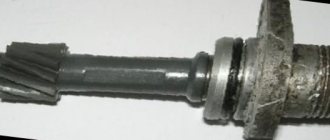
- The rod should not have any backlash, distortion, or bending. Such malfunctions cannot be eliminated, since it will not be possible to achieve ideal direction. The EDS will have to be replaced.
- The most important mechanical part is the driven gear. The presence of broken, worn, or bent teeth will indicate a malfunction with subsequent replacement of the rod and gear as a set.
- If the sensor is fully operational, you need to check the integrity of the drive gear. To do this, you will have to spin the drive wheel of the car. You need to turn the wheel slowly in order to examine in detail all the teeth of this part. The presence of chips or wear will indicate a violation of integrity. Repairing the gearbox will help solve the problem. Perhaps the condition of the gear was affected by foreign solid objects in the manual transmission housing, broken teeth or parts of other mechanisms.
If no faults are detected with the manual transmission sensor and gear, then you should pay attention to the electrical wiring.
It is very easy to replace a faulty sensor yourself. The main thing is to choose an exact analogue. When choosing, you need to consider:
- Rod length.
- Driven gear diameter.
- The number of teeth on it.
It is imperative that the gear is made of metal. Plastic gears wear out quickly: when the oil level in the gearbox is low; operating the machine in fast starts mode.
Wiring
To check, you will need a tester in dialing mode. Next, you need to disconnect the power plug from the ECU. Each wire must be ringed on both sides. There is one significant nuance. The EMF wiring on this Lada model runs next to the collector. A break in the mounting clamps may result in the harness touching the hot manifold body. The wiring should be inspected for melts, defects, and insulation cracks. Any damage must be repaired. Next, you need to check the supply of electrical voltage from the on-board network to the sensor. To do this you need:
- Switch the tester to DC voltage measurement mode.
- Connect the red measuring probe to terminal “1” of the connecting plug on the EMF side.
- Connect the black measuring probe to terminal “3” of the EMF plug.
- Turn on the ignition.
The on-board system must supply 12 volts. Next, you should check the transmission chain from the on-board computer directly to the dashboard to the speedometer. To do this, it is necessary to create a simulation of the arrival of pulses.
- Disconnect the power plug from the ECU to the speedometer.
- Connect one end of the control wire to the “+” terminal of the battery.
- Connect the second end of the control wire to one end of the 1 kOhm resistor.
- Touch terminal “2” on the plug several times with the other end of the resistor.
The arrow should respond by moving when it touches the terminal. If this does not happen, you need to check the drive itself - the receiver of the device. It is worth remembering that the test is carried out only by touch. You cannot fasten the wire to the terminal. The drive operates only on pulse voltage.
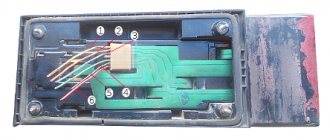
Drive unit
To check the drive, you will have to disassemble the dashboard in order to remove the speedometer along with the drive board. To do this you need:
- Unscrew the 2 fasteners under the panel.
- Unscrew the 2 fasteners under the visor.
- Remove decorative cladding with glass.
- Unscrew the 2 holding screws.
- Disconnect all connectors.
- Remove the panel from its seat.
Then you need to inspect the drive. It is better to start your inspection with the connecting socket. Any dirt or oxides must be cleaned and the contacts pressed. Next, inspect the conductive paths. If there are breaks or oxidation, it is necessary to clean and solder the contacts. To do this, you can use jumpers made of copper wire.
Additionally, you can check the drive.
- The first test method requires connecting voltage to terminal “2” through a 1 kOhm resistor. The arrow should respond to the imitation of impulses by deflecting.
- If the device fails the previous test, then you need to switch the multimeter to resistance measurement mode. Connect the black measuring probe to terminal “3” on the drive connector. Use a red probe to measure the resistance of terminals “2” and “1” one by one. Lack of resistance will indicate a faulty drive. This test can be considered passed only if all conductive paths are in good condition.
The drive - the receiver of electronic speedometers cannot be repaired. It needs to be changed entirely.
When assembling the dashboard, you need to take into account the seating depth of the needle. Deviation towards the overhang will lead to jamming of the part upon contact with the glass.
Replacing the VAZ 2110 speed sensor.
Replacing a used sensor with a working one must be carried out according to the following procedure:
- We find the device. On the ten, it is located on the conductor between the shaft and the speedometer. The device can be easily recognized on the flexible part of the conductor.
- Before dismantling the analyzer, you must turn off the machine engine and turn off the battery power.
- We loosen the fasteners of the device with the appropriate key and remove the holders.
- We dismantle the device and install the correct one in the reverse order.
When replacing the device, it is recommended to also change or lubricate all consumable seals and holders. When dismantling the old element, it is important not to damage the rod. To avoid undesirable consequences, you can remove the drive of the speed indicating device.
Changing the speed sensor on a domestic car is a fairly simple and inexpensive procedure. It is important to understand it with attention to the process in order to obtain the desired results. When replacing a used element, you must be extremely careful. During the replacement process, it is best to use original parts from the manufacturer. Check the updated analyzer in a timely manner and remove dirt from the surface, this way the device will last you much longer. Happy renovation!
Connecting speed sensors and speedometers to the control device (tachograph) “Mercury TA-001”.
Replacement
Now to the question of how to make replacements. To do this, we dismantle the old device and connect a new one in its place. Your steps look like this step by step:
- Remove the negative cable from the battery, which will allow you to turn off the power to the car;
- Now disconnect the wires from the sensor and be sure to remember what form the pinout was in;
- The device can be dismantled by simply twisting it by hand. There is usually no need to use any tools. But if the device fits tightly, then use 22 or 21 millimeter keys. Depending on the modification of your “ten”, the design of the sensor may differ slightly;
- At the same time, we recommend checking the wiring;
- After removing the meter, unscrew the fixing nut that holds the wire going to the gearbox;
- Remove carefully so as not to drop the rod into the box. If this happens, you will have to completely disassemble the gearbox. This is clearly not in your best interest;
- A new device with a rubber ring must be lubricated with transmission fluid so that the fixation in the new place is as reliable as possible;
- Assembly is performed in reverse order;
- Pay special attention to the pinout. Connect the multimeter with the ignition on. If the device showed “minus”, then you connected the wire to positive, which is absolutely not allowed. This is why we initially advised using a sensor that is not labeled 1, 2, or 3.
Connecting a pulse speed sensor
The figure shows a standard speed sensor with ISO 15170-B1-4.1-Ag/K3 connector
Connecting sensors with other types of connectors is done in the same way, depending on the purpose of the contacts.
Line D (pin 4 on the sensor) carries an encrypted signal. Due to the fact that the Mercury TA-001 KU does not have European type approval, it is impossible to use this signal from most sensors in the Mercury KU. However, we recommend laying a 4-wire cable for possible expansions.
Please note that for versions of KU AVLG 816.00.00-10…15 (serial/factory numbers No. 4, when connecting sensors with an output stage of the OK type (open collector, see Table 1 below), it is necessary to use cable AVLG 816.21.00‑02, which is supplied upon request or install a resistor Rd* 10 kOm±10% 0.125 W between contacts B1 and B3 of the tachograph (contacts 1 and 3 of the sensor), as shown above in the diagram.
For KU versions AVLG 816.00.00-16 and higher (serial/factory numbers from No. 000 and higher), an additional resistor at the input is not needed, since it is installed on the KU system board.
Tested sensors
:
Table 1
| Manufacturer | Model | Output type | Note |
| OK - open collector, requires a resistor | |||
| AutoPribor | OK - open collector, requires a resistor | ||
| AutoPribor | OK - open collector, requires a resistor |
Connecting inductive speed sensors and ABS sensors
https://pandia.ru/text/78/003/images/image007_31.jpg" align="left" width="288″ height="217″>
The figure shows a standard European speedometer with connector: ISO 16844-2:2011 (same as on the KU). Speedometers with other types of connectors are connected in the same way, depending on the purpose of the contacts.
In the KU with versions AVLG816.00.00-10...15 (serial numbers No. 4, the output stage B7 was connected to the on-board power supply (12 or 24 V) through a resistor. Therefore, before connecting, you should check the technical data sheet for the speedometer what signal level is acceptable at the corresponding speedometer input.
If the Input is designed for a voltage of no more than 9.5 V, then a resistor Rs* should be connected (shown in the diagram). Select the resistor value according to Table 2. For KU versions AVLG 816.00.00-16 and higher (serial/factory numbers from No. 000 and higher), there is no need to install an additional resistor.
Table 2.
Electrical diagram
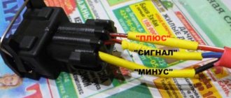
The sensor itself is powered by a voltage of 12 Volts (pink-black cord), and another pin is connected to ground. The gray wire is the sensor output. It is connected to the voltage source through a resistor (see figure).
Typical connection diagram for DS on a VAZ-2112
The complete electrical circuit of the VAZ-2112 car is discussed here.
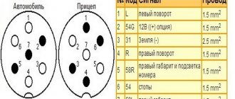
The diagram shows that the output is connected to the ECU terminal. Terminal number:
- 9 – block January 5.1, also BOSCH M1.5.4N (engine 21120, 1.5 l);
- 59 – BOSCH M7.9.7 module (ICE 21124, 1.6 l).
Another gray cord goes to the “red” block on the dashboard, where it connects to terminal 9.
Tidying up VAZ-2112
As you can see, everything is elementary.
Connecting RS485 fuel level sensors.
Currently, Omnicomm RS-485 FLS is supported.
For pinout of inputs, see the corresponding section of the KU Operation Manual.
The control unit automatically adjusts to the connected sensor.
Connecting the CU significantly depends on its design (modification).
— The designation of the CU design as a whole contains:
· in the CU passport (acceptance certificate)
on the nameplate
ALVG 816.00.00-XX
XX Designations of the CU version.
In the following illustrations, for example:
Measuring the speed of a car has long been carried out non-mechanically. A speed sensor is responsible for this, the operating principle of which is based on the Hall effect. This sensor supplies the controller with electromagnetic pulses, on the basis of which the latter calculates the speed of the machine.
Vehicle speed is measured as follows. For each kilometer of distance traveled, the sensor sends a fixed number of pulses to the controller - 6004.
The faster the car moves, the higher the transmission frequency. Thus, the controller calculates the speed based on the time interval between pulses.
In addition to its main function, this sensor indirectly helps the car owner save fuel. When the car is coasting at a speed of over 20 km/h, the controller, based on sensor readings, does not open the fuel supply.
The speed sensor of the VAZ 2114, like all other cars of the VAZ family, including the VAZ-2109, Kalina, Priora, is located on the gearbox, or rather, on the speedometer drive mechanism. To find it, you need to crawl under the hood; it is advisable to remove the adsorber to open up the space (you can do without removing it, but getting to the speed sensor will be more difficult). On the side of the right inner CV joint, you need to find the wire that goes to the gearbox; it is this that is connected to the speed sensor connector.
Design
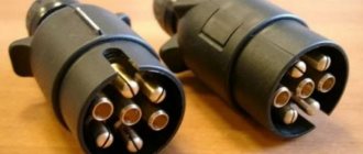
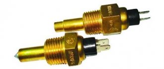
The sensor on the VAZ 2110 comes in two types, and it depends on which gearbox is installed on the car. If the gearbox is from a VAZ 2108, then the sensor is installed on a threaded connection, and if the gearbox is from a VAZ 2110-12, then the sensor is installed through an o-ring and pressed with a bolt to the body.
The design of both sensors is different; one of them is electromagnetic, and the second, older one, converts mechanical movements into electrical signals.
On the left is the sensor of the new type, and on the right is the old one.
Signs of a malfunctioning speed sensor
If the speed sensor malfunctions, it becomes impossible to measure the speed of the car, but that's not all. The worse thing is that this causes interruptions in the operation of the motor. The most common signs that indicate a malfunction are the following, which can only be eliminated by replacing it:
- the speedometer does not work or gives incorrect readings;
- unstable idle;
- increased fuel consumption;
- the engine stops developing full power.
According to statistics, most often a malfunction is indicated by the engine stopping at idle, when the car is coasting, or when the driver presses the clutch to change gear. Typically, the Check engine indicator lights up on the instrument panel, and if the car is equipped with an on-board computer, it displays error code “24”.
If the speed sensor on the Kalina is faulty, the symptoms include inoperative electric power steering and increased sensitivity of the fuel gauge to the level of gasoline in the tank.
Troubleshooting
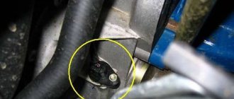
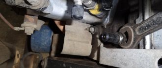
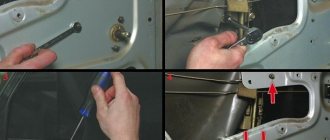
To begin troubleshooting the problem, you first need to find the device. From the photo you can determine how the speed sensor on the VAZ 2110 looks externally.
Ears for fastening
As for its location, look in the engine compartment in close proximity to the exhaust manifold. They say frankly that the place where it is installed cannot be called ideal. It's all about the collector. While the car is running, the manifold heats up. The sensor wires rub against it, which over time leads to malfunctions and short circuits.
Therefore, experts recommend that the first step is to properly insulate the wiring, and also use some kind of clamps so that the wires do not come into contact with the collector. This significantly extends its service life.
Having checked the device visually and not determining the presence of breakdowns, this tells us that the element itself is faulty. This problem can be solved by replacing it.
Causes of speed sensor malfunction
Most often, malfunctions occur when the electrical circuit is broken, so diagnostics should begin with checking the wires and contacts. Oxidized or dirty contacts must be cleaned and coated with some kind of lubricant, for example “Litol”.
A possible broken wire should be looked for near the connector. At this point they bend and often fray. You also need to check the integrity of the wire insulation in the exhaust manifold area. It can melt, after which a short circuit occurs.
The cause of a sensor malfunction may be a worn speedometer cable. Over time, breaks and burrs appear on it, which subsequently lead to the sensor failure.
How to check the speed sensor on a VAZ-2109
Checking the speed sensor begins by finding out whether 12 V is supplied to its contacts.
Since its operating principle is based on the Hall effect, the contact through which the pulse signals pass can only be tested by torsion. The voltage varies in the range from 0.5 V to 10 V.
There are three ways to check the device; the first two require a multimeter.
First way
- the sensor is removed;
- using a multimeter you need to find out what each contact is responsible for, you need to find the pulse one;
- the positive probe is connected to the pulse contact, and the negative probe is connected to the car body or engine;
- A piece of tube is put on the sensor axis and rotates at a low speed, while the voltage is measured with a multimeter: the higher the rotation speed, the higher the pulse frequency and voltage.
Second method (without dismantling)
- use a jack to lift one of the front wheels of the car;
- the multimeter is connected to the sensor wires;
- you need to rotate the wheel and check whether pulses appear (if so, the device is working normally).
Third method (without a multimeter)
If a measuring device is not available, the test can be performed using a test lamp or a regular 12-volt light bulb. The procedure is similar to the second method.
- The pulse wire is disconnected from the sensor;
- with the ignition on, use a control lamp to find “plus” and “minus”;
- the wheel is hung out;
- the control lamp is connected to the signal wire, the wheel rotates (if the “minus” lights up on the control, the sensor is working).
If you don’t have a warning lamp at hand, you can use a 12-volt one (for example, from a turn signal). The wire connects the battery plus and the signal contact. If the sensor is operational, the light will blink.
If the check shows that the device is working properly, you need to check how its drive works. To do this, the front wheel is hung out. You need to find the sensor drive by touch. Then you need to rotate the wheel with your foot, and with your hand you need to check whether there is rotation in the drive and whether it is stable.
Repair and replacement
We carry out dismantling according to the following scheme:
- We de-energize the car by removing the “-” connector from the battery;
- We disconnect the wire connector from the sensor and remember what their pinout is;
- We unscrew the sensor itself by hand. If this doesn’t work, use key 21 or 22 (there may be design differences);
- At the same time, we check how the drive feels. After removing the sensor, you need to unscrew the nut with which the drive is attached to the gearbox. You need to remove it very carefully, since if you drop the rod into the gearbox, you will have to disassemble it too. The new drive has a rubber ring, which is lubricated with transmission oil before installation.
Replacing the speed sensor on a VAZ-2109
A faulty speed sensor cannot be repaired. Replacement is quick and easy. To work you will need keys “10” and “21”. First of all, the battery is disconnected from the on-board network, then the speed sensor connector is disconnected.
After this, the sensor itself is unscrewed. If its rod breaks, you will have to dismantle the drive. This must be done carefully so as not to drop the broken rod inside the gearbox.
Installation is carried out in reverse order. The actuator rod is inserted into the sensor sleeve, the rubber O-ring is lubricated with oil, after which the device is screwed into place.
After the replacement has been made, it is necessary to reset the ECU errors, otherwise it will still consider the speed sensor to be faulty, and the replacement will not have the desired effect.
Failures of the speed sensor are manifested by false data from the speedometer, and the Check Engine light appears on the instrument panel. If this is the case, then the cause is the speed sensor.
To identify a malfunction, you first need to know where the speed sensor is located in the VAZ-2110, and after detection, you need to check its drive. It is located under the hood, in the engine compartment, next to the exhaust manifold, against which the wires rub. In most cases, it is enough to insulate the wires and place them so that they have no contact with the collector. Also, do not forget about a broken cable, because this is also a possible cause of failure. If you do not see any problems on it, then the problem is in the sensor or in its drive.
In order for the replacement of the VAZ-2110 speed sensor to be successful, it is first necessary to restore the speedometer's functionality. A little advice: when buying a sensor, it is advisable to choose one with the designations “–”, “A”, “+”, and not as usual - 1, 2, 3. Although this does not play an important role, it will help to make the pinout faster.
The second important point is the choice of a device with a metal rod, because it will last much longer than its plastic counterpart. Don’t forget to check the rotation of the rod, whether there is any play in it, or whether you forgot to install the washer.
- We turn off the power to the car by removing the connector from the battery.
- We disconnect the wire connector from the sensor, remembering the pinout.
- We unscrew the sensor manually, if unsuccessfully, then use the key 21 or 22 (depending on the design).
- We look at the state of the drive. After removing the sensor, it is necessary to disconnect the nut that secures the drive to the gearbox. The new drive has a rubber attachment that needs to be lubricated with transmission oil.
We install new devices by doing everything in reverse order. After installation, you need to check the polarity of the wires with a multimeter. If the “+” contact is connected to “–”, then they must be swapped. To do this, it is advisable to choose the block that we recommended. But if there is none, then we follow the following sequence: 1 – “+”, 2 – signal output, 3 – “–”.
Any car existing in the world is necessarily equipped with a special system designed to measure the speed of the vehicle and transmit this information to the ECU. Carbureted vehicles use a cable (mechanical) speedometer system, so a speed sensor is not required. Therefore, on VAZ 2110, 2111 and 2112 it is mounted only on injection vehicles - this system is electronic and is responsible for controlling the operation of the power unit. Replacing a speed sensor is a rather labor-intensive task, but not at all difficult. More on this later in the article.
The purpose of this device is to “set” the ignition timing, control the quality of the fuel mixture and correct fuel supply. The sensor collects a lot of information for the injection engine, such as engine speed, detonation level, speed, etc., and transmits digital signals to the electronic unit. In turn, this data is checked here and appropriate adjustments are made to the operation of the injector. As a rule, the speed sensor is located under the hood, in the engine compartment, near the exhaust manifold.
Types of speed sensors, their differences. Where is the speed sensor located?
Electronic 6-pulse sensors are equipped with cars with injection engines, launched into series since 2006.
On carburetor Samaras you can sometimes find 10-pulse EMF.
- Until 2006, VAZ cars used mechanical devices in the form of special inserts between the speed indicator cables and the gearbox gear outputs.
- On the VAZ-2110 (2111, 2112), speed sensors are mounted on the gearbox housings slightly to the right along the route, directly next to the oil control dipstick.
- The device is easy to find by looking in the area of the right CV joint.
- On the VAZ-2115, the electronic device is mounted on top of the front part of the gearbox (along the way) directly above the differential. The product with the connected cable is secured with one bolt on the box body.
The key difference between different types of EMF is the absence of wires and connecting connectors. For example, GM or Yantar systems are equipped with products with round (oval) ports. At the same time, Bosh uses wireless versions with square connectors.
Signs of a malfunctioning speed sensor
If the odometer suddenly refuses to work, and the speedometer “lies” regarding mileage and speed or works jerkily, this indicates incorrect operation of the speed sensor or its drive. There may also be problems in the electrical circuit, the pinout is mixed up, the connector is failing, and so on. In addition, the fact that the vehicle stalls at idle may also indicate a malfunction of the speed sensor, but there may be a lot of other reasons for this. Of course, if the speedometer deliberately gives false readings, and the “CHECK ENGINE” lamp is on on the instrument panel, then the reason is a failed speed sensor.
Troubleshooting
First you need to know where the VAZ 2110 speed sensor is located, and then check its drive. It is located under the hood, in the engine compartment, next to the exhaust manifold. It is on the heated collector that wires sometimes rub and melt.
Replacing the plug and speed sensor
Changed the sensor
speedometer and found that the wires going to the plug were completely frayed! I had to solder it.
Lada Kalina speedometer does not work. Replacing the speed sensor connector
Maybe this video will help someone. The speed sensor is not always at fault
. By the way, the old sensor turned out to be working.
The result is a short circuit. Usually it is enough to insulate the wires, then route them so that they do not touch the collector.
Wiring pinout, what to pay special attention to when using a multimeter
Pay attention to the pinout inside the block. With the ignition on, use a multimeter to determine which connector is connected to which wire. If you connect the wire to the “plus” connector, and the multimeter shows “minus”, then you should urgently change the polarity. Therefore, it is advisable to take a block with the appropriate designations. But if this doesn’t happen, you can take the regular one. In this case, the pinout is as follows - 1 is “+”, 2 is “signal output”, and 3 is “-“.
At the last stage, do not forget to check the drive, as well as the operation of the vehicle as a whole with the wheels hanging or while the vehicle is moving.
Preparing for replacement
In order for the replacement of speed sensor to be successful and bring the expected result, first of all - the resumption of normal operation of the speedometer, you need to prepare for it, then carry it out correctly.
When choosing a new sensor, pay attention: it is desirable that each connector inside the block has the designations “-, then A and ” instead of the usual 1, 2, 3. Although this does not seem to have any fundamental significance, this way the pinout will be carried out faster, and, the main thing is correct.
Read
Speed sensor pinout
Another important point is to choose a device with a metal stem, which will last much longer than the six months “allotted” for a plastic one. Don’t forget to check how the rod rotates, whether there is any play in it, and whether you forgot to equip it with a washer.