3.9/5 — (65 votes)
The article will describe the pinout of the VAZ 2114 ECU and discuss all the modifications and features of this device. As you understand, any modern car is a whole arsenal of sensors and mechanisms. And they allow you to squeeze maximum power out of the engine without changing its volume. In order to independently repair electronics or carry out firmware, you need to know what a control unit is and on what principles it operates.
Where is the VAZ 2114 ECU located?
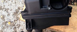
The block is located in the dashboard, directly under the tidy. To replace or dismantle, you need to unscrew the screws and remove the panel from the side, on the passenger side. Through the resulting hole you can see the ECU housing - it is installed inside a steel retainer.
To remove the electronic control unit, you need to unscrew the bolt and carefully pull out the housing, grasping the latch. Of course, it is necessary to turn off the power from the on-board network, otherwise expensive equipment can be damaged. A short circuit is the enemy of any electrical appliance, so be careful. It is advisable not only to remove ground from the battery, but also to disconnect the positive wire.
Work sequence
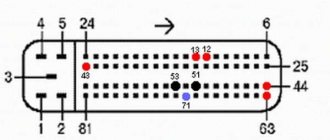
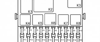
Diagnostic connector pinout
Before dismantling the device, you should disconnect the negative terminal from the car battery:
The vehicle must be placed on a flat surface, without slopes, and the parking brake must be set. The following stages of work are performed inside the car
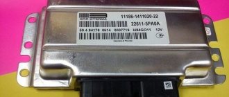
You will need to carefully unplug the wire connector from the control box, but before doing so, you should unplug the latch. When you get directly to the powertrain control controller, using a wrench you will need to unscrew the two nuts that secure the module to the bar. After these nuts are unscrewed, you will need to move the bar itself slightly to the right side, this will allow it to be released from engagement. After completing these steps, the control controller can be dismantled. If you are replacing a device, then if it breaks down, you should replace the module with a similar one that was installed
That is, if you had a January 7.2 ECU, then the same module is installed. If the unit is subject to repair, it should be repaired and then reinstalled. The installation procedure is performed in the same way, only in reverse order.
Do not repair the control unit if you have never had to deal with such a task before!
How does the ECU work?
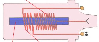
At the heart is a microprocessor, which is responsible for the normal functioning of all key devices. On a VAZ 2114 car, the ECU collects data from sensors:
- Vehicle speed.
- Detonations.
- Lambda probe.
- DPKV.
- Air flow.
- TPDZ.
- Phases of injection of the air-fuel mixture.
- Coolant temperatures.
These are reading devices that collect information about the operation of an internal combustion engine. Why does he collect it? It is correct to divide and conquer by the following actuators:
- Fuel supply system (pump, injectors).
- Ignition system.
- Adsorber.
- Ventilation.
- Idle air control (yes, yes, this is not a sensor, but an actuator, no need to be confused).
- Automatic diagnostics.
The block diagram of the electronic control unit on the VAZ 2114 consists of three cascades, each of which has its own memory modules:
- A RAM unit (random access memory) is a system that has short-term memory. It stores all information about errors that occurred during operation during the current engine start. When the ignition is turned off (and the computer is de-energized), all memory is cleared and filled again the next time it starts.
- PROM is a programmable read-only memory device. This is the block in which the fuel map (firmware) of the electronic control unit is stored. It also permanently stores information about all system calibration results. And most importantly, this memory contains the algorithm of the internal combustion engine control system. This memory is permanent and is not erased even if the on-board network is completely disconnected. It is this block that is programmed when the “firmware” procedure is performed to improve the characteristics of the VAZ 2114 car.
- And the last block is the ERPZU. The memory unit is necessary to ensure the normal operation of the anti-theft system on the car. It stores passwords and encodings. Starting the engine is possible only if the data exchanged between the immobilizer and the EEPROM matches.
Electrical diagram of the VAZ-21104 ECM with controller 21124-1411020-30/31/32
1 — block of the ignition coil wiring harness to the ignition system harness; 2 — block of the ignition system harness to the ignition coil wiring harness; 3 — ignition coils; 4 — immobilizer warning sensor; 5 — immobilizer control unit; 6 — spark plugs; 7 — nozzles; 8 — diagnostic block; 9 — block of the ignition system harness to the ABS cabin group harness; 10 - controller; 11 — electric fuel pump; 12 — block of the ignition system harness to the fuel level sensor harness; 13 — block of the fuel level sensor harness to the ignition system harness; 14 — block of the ignition system harness to the injector harness; 15 — injector harness block to the ignition system harness; 16 — block of the ignition system harness to the side door harness; 17 — speed sensor; 18 — idle speed regulator; 19 — throttle position sensor; 20 — coolant temperature sensor; 21 — mass air flow sensor; 22 — oil pressure warning lamp sensor; 23 - phase sensor; 24 — oxygen sensor; 25 — crankshaft position sensor; 26 — knock sensor; 27 — solenoid valve for purge of the adsorber; 28 — oil level sensor; 29 — coolant temperature indicator sensor; 30 — block of the ignition system harness to the instrument panel harness; 31 — block of the instrument panel harness to the ignition system harness; 32 — ignition relay; 33 - ignition relay fuse; 34 — fuse for the electric fuel pump power supply circuit; 35 — electric fuel pump relay; 36 — electric fan relay; 37 — controller power supply fuse; 38 — ignition system harness block to the air conditioner connector; 39 — instrument cluster; 40 — ignition switch; 41 — electric fan of the cooling system; 42 — on-board control system unit; 43 — starter relay; 44 — contacts of the 8-terminal blocks of the instrument panel harness and the front harness; 45 — contacts of the 21-terminal blocks of the instrument panel harness and the rear harness; 46 — trip computer; 47 - diagnostic connector.
Repair and diagnostics of control units
The VAZ 2114 controller often breaks down. The system has a self-diagnosis function - the ECU queries all components and issues a conclusion about their suitability for operation. If any element fails, the “Check Engine” lamp will light up on the dashboard. It is possible to find out which sensor or actuator has failed only with the help of special diagnostic equipment. Even with the help of the famous OBD-Scan ELM-327, loved by many for its ease of use, you can read all engine operating parameters, find the error, eliminate it and delete it from the memory of the VAZ 2114 ECU.
Of course, it is wrong to simply delete errors. Be careful, because malfunctions don’t just appear. A good example is that a friend’s oxygen sensor broke down. And every other day he cuts down the mistake so that “it doesn’t become an eyesore.” But the reason lies in a faulty lambda. But what to do if the ECU does not want to respond to the scanner at all? Then check the following:
- Is there any mechanical damage to the housing, including oxidation and corrosion?
- The fuse is working properly, there is voltage and a connection to the power supply minus.
- Is the device overheating?
Video “No spark and blown fuse - repairing the ECU”
What to do if there is no spark and the fuses are constantly blowing - the video below shows the process of repairing the control controller in a garage (the author of the video is the Auto Practice channel).
I came across an article by McSystem. Actually, here it is below
In January - about Januarys. Again and in detail about the ECM-ECU masses
One of the rather serious problems affecting the stable operation of engines controlled by the January ECU (7.2, 7.2+, M73, 7.9.7) is the “mass problem” of the ECM. Moreover, the point is not so much in bad (or uncrimped) contacts and their fastenings, but rather in the rather incorrect wiring of the ECM harness itself. And the solution is not in “pulling a fancy cable (KG-25 or 50)” to the ECU. Therefore, this material will be devoted to a technically competent approach to solving this problem. What is described below is a kind of compilation, or an attempt to “chew” what has been published more than once, in particular on ChipTuner.ru, and to convey to readers the specifics of solving this problem. The articles by I.N. turned out to be the most complete and informative. Skrydlova, (aka Aktuator) “About the masses”, “MASS: AN UNEXHAUSTABLE SOURCE OF GLITCHES” “ONCE AGAIN ABOUT THE MASSES” Oleg Bratkov. Many years ago, having read and comprehended what was written, I implemented it on my typewriter. I completely agree with the conclusion of the author (aka Aktuator): “All the assurances of AVTOVAZ OJSC about improving the quality of electrical connections in manufactured vehicles are not worth a penny. In most cases, it is possible to achieve normal operation of the engine under the control of the ECM I 7.9.7 and January 7.2 only by carrying out additional, and not accepted by the manufacturer as a warranty, work to change the electrical circuit of the car.”
So, on to the topic! Classic ECM 21124 with ECU January 7.2(+) or M7.9.7 Electrical connection diagram of ECM EURO-2 M7.9.7, January 7.2 LADA 2110 with engine 21124. 21124-1411020-30, 21124-1411020-31.32
Fig. 1 ECM 21124 January 7.2, M7.9.7 Noticed, often described and characteristic problems - unstable idle speed, freezing speed, “jerking” of the engine at start and operation of the cooling fan, unreasonable jumps in the electrical parameters of the ECM during diagnostics. And this is not the entire list. And the whole problem is a rather incorrect wiring of the harness masses, not in relation to the body, but to the ECU. Therefore, in this article you will not see recommendations for tightening the “hoses” of additional mass to the ECU, due to its complete uselessness. This is not a newfangled “razmasovka” or “razminusovka”... Don’t get your hopes up!
The main idea voiced by the authors is that the wiring of the power lines of the ECU and fan and low-current sensor masses is fundamentally incorrect. Rice. 12
Fig.2 Ground connections of the ECM. S6, S7, S8
The sensors must be connected to the ground bus of the ECU board and not have contact with the body! There should be no flow of pulsed and direct currents of the ECU and IM in the sensor mass circuit. And the ECU is securely connected to the body. The rationale is to eliminate the influence of ECU currents (pulse and constant) and fan current on the reliability of sensor readings. Classic approach with data collection and processing systems! But not from AvtoVAZ designers, as usual... Now, in order
Fig. 3 Masses according to AvtoVAZ, or how not to do it
1. The ECU masses are combined into three crimps S6, S7, S8, which are combined with each other and TWO bends are already made from them to the body studs B3, B4. 2. A switched minus fan with a rated current of 12A is connected to S6, and at the peak at start - all 20A! ! ! Which in itself is terrible! 3. All this is connected (screwed) to the ECU bracket, which in turn is very flimsily connected to the body. The engine ECM consists of sensors and actuators (AM). Sensors can be easily divided into analog and discrete. Analogue – mass air flow sensor, air pressure sensor, diesel sensor, DD. The output signal of these sensors is a voltage in a certain small range, usually 0 - 5V. For this group, any (even small) interference has a serious impact on the result. Discrete ones - DC (to some approximation), DF, DS (Speed Sensor) - are less critical to interference, because the output signal has two fixed levels high and low, and intermediate levels are not interesting to the ECU. Actuators - ignition coils, injectors, canister valve, DC heating, IAC, relays and other sources of large pulsed and direct currents along the negative (mass) bus of the ECU. To understand what the developers were up to, let’s look at the diagram in Fig. 3 – this is a fragment of the main ECM diagram in expanded form. It immediately catches your eye - the masses of the most sensitive and responsible sensors, mass air flow sensors and diesel fuel sensors, are wired, although there are separate pins for them, 36 and 35, respectively. For what? Silence in response! S6-S7-S8 are connected by jumpers, which makes the situation even worse.
Electric type fuel pump
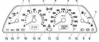
Diagram and pinout of the Niva 4x4 instrument panel (VAZ 2121, 2131)
The fuel pump for VAZ 2110 is an electric injector and is installed in cars with an adjustable injection system. The “tens” electric fuel pump is located in the fuel pipeline system in the vehicle’s gas tank. This dislocation of the element greatly reduces the possibility of fuel loss due to the use of a scheme without the participation of pipelines that work to suck in fuel.
This element of the fuel supply system includes:
- a pump, the body of which is made of metal;
- fuel level sensor;
- fuel intake component;
- filter mesh;
- check valves and pressure reducing valves.
The valve of the reverse principle of action stops the fuel distribution complex when the power plant is stopped. A pressure-reducing element controls pressure by acting as a bypass valve.
The designs of electric fuel pumps are:
- roller type;
- gear type;
- centrifugal type.
An electric roller pump sucks in fuel and drives it through the functionality of the rotor element and the movement of special purpose rollers. The gear electric pump sucks in fuel and drives it through and is pumped by moving an internal gear relative to the stator element, which plays the role of an external gear. When a rotational type rotor moves, the side elements of the tooth create a chamber in their segments that changes the degree of rarefaction, with the help of which the effect of suction and supply of fuel is created.
At the same time, a centrifugal type fuel pump is mounted directly in the fuel line. Such elements make it possible to ensure an even supply of fuel and operate almost silently. They have one significant feature - a limit on pressure parameters and functionality.
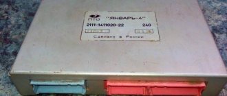
Commercial firmware JANUARY 7.2 for HBO
| Single-mode versions | |
| 201CB5711183 – 1411020-22 | Single-mode version optimized for basic LPG movement. Without DC, with CO adjustment from diagnostic equipment. Cost 1000 ₽. |
| 203RB402111 – 1411020-81(82) | Single-mode version optimized for basic LPG movement. Without DC, with CO adjustment from diagnostic equipment. Calibration by Aviacop Tuning Lab. Cost 1000 ₽. |
| 204RB4021114 – 1411020-31(32) | Single-mode version optimized for basic LPG movement. Without DC, CO adjustment with diagnostic. equipment. Protocol Russia-83. Cost 1000 ₽. |
| 205RB4021124 – 1411020-31(32) | Single-mode version based on the I205DX53_RCO software, optimized for the main movement on the HBO. Without DC, with CO adjustment from diagnostic equipment. Protocol Russia-83. Calibration by Aviacop Tuning Lab. Cost 1000 ₽. |
| 226BX1221067 – 1411020-11(12) | Single-mode version optimized for basic LPG movement. Without DC, with CO adjustment from diagnostic equipment. Calibration by Aviacop Tuning Lab. Cost 1000 ₽. |
| Dual mode versions | |
| 201CDB5711183 – 1411020-22 | Dual-mode Standard/Butane version. When switching to GAS, the injectors and BN are switched off by software. Cost 1200 ₽. |
| 203DRB402111 – 1411020-81(82) Dual-mode version | Dual-mode version Speaker/Butane. The dynamic commercial version I203DX36 is used as the gasoline version, and I203RB40 as the butane version. When switching to GAS, the injectors are switched off programmatically. Cost 1200 ₽. |
| 204DRB4021114 – 1411020-31(32) Dual-mode version | Dual-mode version Speaker/Butane. The dynamic commercial version I204DX55 is used as the gasoline version, and I204RB40 as the butane version. When switching to GAS, the injectors are switched off programmatically. Cost 1200 ₽. |
| 205DRB4021124 – 1411020-31(32) Dual-mode version | Dual-mode version Speaker/Butane. The dynamic commercial version I205DX53 is used as the gasoline version, and I205RB40 as the butane version. When switching to GAS, the injectors are switched off programmatically. Cost 1200 ₽. |
| 226BP1221067 – 1411020-11(12) Dual-mode version | Dual-mode version Dynamic/Butane for “Classic”. The dynamic commercial version I226FX12_RCO is used as the gasoline version, and I226BX12_RCO as the butane version. BN and injectors cannot be turned off by software, an emulator is required. Cost 1200 ₽. |
| 226BFX5321067 – 1411020-11(12) Dual-mode version | Dual-mode version Dynamic/Butane for “Classic”. As a basic version, a dynamic commercial version based on “front-wheel drive” software was used; when switching to GAZ, the injectors are turned off by software, and a correction was made to work with LPG. Cost 1200 ₽. |
| 214BXF2 Dual mode version | Dual-mode version Dynamic/Butane to replace Bosch M7.9.7 controllers for January 7.2 Niva vehicles. As a basic version, a dynamic commercial version is used based on “front-wheel drive” software, with 2 cooling fans; when switching to GAS, the injectors are turned off by software, and a correction has been made to work with LPG. Version for fuel systems with return. Cost 1200 ₽. |
| 220BXF2 Dual mode version | Dual-mode version Dynamic/Butane to replace Bosch M7.9.7 controllers for January 7.2 Niva-Chevrolet vehicles. As a basic version, a dynamic commercial version is used based on “front-wheel drive” software, with 2 cooling fans; when switching to GAS, the injectors are switched off by software, and a correction has been made to work with LPG. For fuel systems without return. Cost 1200 ₽. |
Search this blog
Firmware and modification of Bosch ME7.9.7, Bosch M797(+), Kefico units
The control unit supports the following commands for reprog: Establish communication Read / Write FLASH Read / Write EEPROM / ECU passport (Bosch M797 and M797+ ECU only)
Attention! All operations during reprogramming are performed with the unit, which is switched to programming mode, after the “Establish communication” operation is performed, which is necessary to transfer the control unit from diagnostic mode to reprogramming mode.
To program the ECU on the table, it is necessary to modify the unit, which will be discussed below. Firmware file size for FLASH memory:
Bosch M797 – 512 KB (524288 bytes), EEPROM memory – 512 bytes. Bosch M797+ – 832 KB (851968 bytes), EEPROM memory – 512 bytes.
Due to the fact that the Kefico ECUs installed on KIA / HYUNDAI cars, as well as the M797 ECUs on Chery Amulet, Geely cars are schematically very similar to the Bosch M797, reprogramming these control units is similar to reprogramming the Bosch M797 ECU.
Pinout options
Depending on the operating protocol, pinout options are allowed:
When using the standard ISO 9141-2 protocol, it is activated via pin 7, while pins 2 and 10 in the connector are inactive. For data transmission, pins numbered 4, 5, 7 and 16 are used (sometimes pin number 15 can be used).
- Documentation
With a protocol like SAE J1850 in the VPW (Variable Pulse Width Modulation) version, pins 2, 4, 5, and 16 are used. The connector is typical for American and European General Motors cars.
Using J1850 in PWM (Pulse Width Modulation) mode provides additional use of pin 10. This type of connector is used on Ford products. The J1850 protocol in any form is characterized by the non-use of pin number 7. Start of form
Of course, for many, such diagrams and descriptions of OBD2 connector pinouts are very complex and unnatural. Often, motorists prefer to periodically take their car to a specialized car service center and not even think about diagnostic connectors and, especially, about their pinouts. But it is still worth recognizing the usefulness of self-diagnosis. Experienced motorists say that it is necessary for every car owner to have a diagnostic scanner in their car to quickly check their doubts about the operation of the car, check for errors, settings and the like, which, first of all, will save significant money.
Obvious advantages of self-diagnosis via the OBD2 connector:
- Saving money, service stations charge a lot of money for simple computer diagnostics
- To promptly find out the error and understand the malfunction without the help of specialists, you don’t need to be nervous at the service station and you can avoid imaginary breakdowns, as often happens in unscrupulous services.
Good luck on your journey and in diagnosing your car!
Article: 346027
Order code: 095401
- Buy with this product
- show more
Buy analogues
- There are no reviews for this product yet.
Schematic electrical diagrams, connecting devices and pinouts of connectors
The fuel pump on a car is designed to supply fuel to the combustion chamber. Its operation is controlled using a relay. On a VAZ (depending on the model), the fuel supply unit can be electrical or mechanical - it all depends on the fuel supply system. On a fuel-injected car, the fuel pump is located in the tank. When the ignition is turned on, voltage is supplied to the terminals of the unit and it begins to pump fuel. If the required pressure is created in the system, the relay automatically turns off the fuel pump - the engine is ready to start.
When the ignition is turned on, the relay creates pressure in the fuel lines by turning on the fuel pump (BN) for a couple of seconds. After this, the BN will work either when the engine is cranked by the starter, or when the engine is running.
Sometimes this system needs repairs - there is nothing complicated here, and the editors of the 2Skhema.ru website will tell you how to do it yourself. Let's start with the BN pinout, then we will indicate it on the diagrams and at the end there will be instructions for replacing the fuel supply elements.