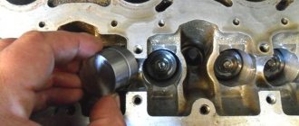
I decided to check the ADC on the mass air flow sensor. full article here. mayvaz.ucoz.ru/index/datc…hoda_vazdukhaju_dmvr/0-23 1. Turn on the tester in DC voltage measurement mode, and set the measurement limit to 2 Volts. We find in the sensor connector a yellow wire - output (closest to the windshield) and a green wire - ground (third from the same edge). These are the sensor pins we need. In systems of different years, colors may change (! and the connector may already be changed), only the location of the pins remains unchanged. To assess the condition of the mass air flow sensor, it is necessary to measure the voltage between the indicated terminals with the ignition on, but NOT starting the engine! The diameter of the tester probes allows you to penetrate through the rubber seals of the connector, along the specified wires, without disturbing their insulation, reaching the contacts themselves and without causing harm to the seals themselves. It will be useful to spray HP grease on the probes. Turn on the ignition, connect the tester, take readings. The same readings can be taken without a tester from the on-board computer display, if anyone has one. In the “voltage from sensors” parameter group. Designated Udmrv=…
2. Evaluate the results. The voltage at the output of a working sensor in the “out of the package” state is 0.996…1.01 Volts. During operation, it gradually changes and, as a rule, increases. By increasing this voltage, one can quite confidently judge the degree of “wear” of the sensor. A voltage within the above range is the best result of this test. Further options are possible: 1.01…1.02 - a completely working sensor, very good. 1.02…1.03 is also acceptable, but the sensor is no longer young. 1.03…1.04 - most of the resource is already behind, you can plan for a quick replacement. 1.04…1.05 - clearly a tired sensor, it has already served its purpose. If your budget allows, feel free to change it. 1.05...and higher are a source of problems, it’s high time to replace them.
Measured:
between the yellow and battery negative 1.052 V, (apparently the masses need to be cleaned) between the yellow and green wire 1.014 V. (sensor is live)
It is best to take the ground from the green wire, because this is exactly the voltage that the controller sees.
Here I found useful information on typical parameters. Made essentially as a note to myself.
For many novice diagnosticians and ordinary car enthusiasts who are interested in the topic of diagnostics, information about typical engine parameters will be useful. Since VAZ car engines are the most common and easiest to repair, we’ll start with them. What should you pay attention to first when analyzing engine operating parameters? 1. The engine is stopped. 1.1 Coolant and air temperature sensors (if equipped). The temperature is checked to ensure that the readings correspond to the actual engine and air temperatures. It is better to check using a non-contact thermometer. By the way, one of the most reliable in the injection system of VAZ engines are temperature sensors.
1.2 Throttle position (except for systems with an electronic gas pedal). The gas pedal is released - 0%, the accelerator is pressed - according to the opening of the throttle valve. We played with the gas pedal, released it - it should also remain 0%, while the ADC with a dpdz of about 0.5V. If the opening angle jumps from 0 to 1-2%, then as a rule this is a sign of a worn out valve. Less common are faults in the sensor wiring. With the gas pedal fully pressed, some units will show 100% opening (such as January 5.1, January 7.2), while others such as Bosch MP 7.0 will show only 75%. This is fine.
1.3 MAF ADC channel in rest mode: 0.996/1.016 V - normal, up to 1.035 V is still acceptable, everything above is already a reason to think about replacing the mass air flow sensor. Injection systems equipped with feedback from an oxygen sensor are able to correct, to some extent, incorrect readings of the mass air flow sensor, but there is a limit to everything, so you should not delay replacing this sensor if it is already worn out.
2. The engine is idling.
2.1 Idle speed. Typically this is 800 - 850 rpm with a fully warmed up engine. The idle speed value depends on the engine temperature and is set in the engine control program.
2.2 Mass air flow. For 8-valve engines, the typical value is 8-10 kg/h, for 16-valve engines - 7-9.5 kg/h with a fully warmed-up engine at idle. For the M73 ECU these values are slightly higher due to a design feature.
2.3 Length of injection time. For phased injection, the typical value is 3.3 - 4.1 ms. For simultaneous – 2.1 – 2.4 ms. Actually, the injection time itself is not as important as its correction.
What is an analog-to-digital converter (ADC)?
Analog-to-digital converters (ADCs) are one of the main elements of modern data acquisition systems. Such systems consist of the following basic components:
- sensors (see the reference book “What are sensors?”);
- signal converters (see the guide “What is signal conditioning?”);
- analog-to-digital converters (ADC) (this article)
- and some kind of computer with data acquisition software that allows you to record and analyze signals.
ADCs play a large role in modern digital data acquisition systems
Parameters of ADC sensors VAZ
- Registration
- Entrance
- To the beginning of the forum
- Forum Rules
- Old design
- FAQ
- Search
- Users
Sorry for maybe stupid questions
As I understand it, this is a crimp on the sensor masses, located 20cm from the ECU connector?
And here is the “wire from the ECU to the 3rd contact of the mass air flow sensor”
on the diagnosis and according to the tester (3rd and 5th contacts of the air flow sensor) 0.996
When driving at low throttle, when releasing the gas, driving at idle and when switching, it jerks. It seems like symptoms of a mass air flow sensor.
Main types of analog-to-digital converters
Although there are five main types of ADCs available today, in data acquisition it all comes down to two:
- successive approximation ADC and
- delta-sigma.
Other types are also quite effective, but are better suited for non-data collection applications. For example, dual ADCs operate rather slowly and are therefore mainly used in hand-held voltmeters.
Additionally, there are parallel ADCs that provide extremely high sampling rates, but their amplitude-axis resolution is too low for data acquisition needs. Pipeline ADCs rely on the use of multiple parallel converters to increase amplitude axis resolution, but their capabilities are still limited.
Comparison of the main types of ADCs
| ADC type | Advantages | Flaws | Max. permission | Max. sampling rate |
| Twin | Low cost | Low speed | 20 bit | 100 Hz |
| Parallel | Very fast | Low bit resolution | 12 bit | 10 GHz |
| Conveyor | Very fast | Limited Resolution | 16 bit | 1 GHz |
| Successive approximation (SAP) | Good ratio of speed and resolution | No internal distortion protection | 18 bit | 10 MHz |
| Delta Sigma (ΔΣ) | High dynamic performance, anti-distortion | Lag on artificial signals | 32 bits | 1 MHz |
Thus, data acquisition specialists settled on successive approximation ADCs (SAADs) and delta-sigma (ΔΣ) ADCs . Each of them has its own advantages and disadvantages and, therefore, is suitable for solving certain problems. Let's look at the operating principle of each ADC and compare them:
Successive approximation ADC (SAAD)
The “workhorse” of the data processing industry is the RPP analog-to-digital converter. It provides an excellent balance of speed and resolution and processes a wide range of signals with excellent accuracy.
This converter has been around for a long time, so the RPP models are stable and reliable, and the chips are relatively inexpensive. They can be configured for both simple ADC cards, where one ADC chip is “shared” by several input channels (multiplexed ADC cards), and for models where each input channel has its own ADC for simultaneous sampling.
Block diagram of a typical RPP
The analog input of most ADCs is 5V, so almost all signal conditioning interfaces convert it the same way. A typical SAR ADC uses a sample-and-hold circuit that receives the converted analog voltage from the signal conditioning interface.
The on-chip processing system produces an analog reference voltage equal to the digital code output of the sample-and-hold device. Both signals are sent to the comparator, which sends the comparison result to the RPP. This process continues for n consecutive times, with n being the bit resolution of the ADC itself, until a value closest to the actual signal is found.
SAR ADCs do not have an internal filtering/smoothing mechanism, so if the data acquisition system does not provide such a component in front of the ADC, if the sampling rate is set too low, false signals (aka “noise”) will be digitized by the SAR ADC. Distortion is especially problematic because it cannot be corrected once digitized.
There is no way to fix it using software. This must be prevented by continuously sampling above the Nyquist frequency of all input signals, or by filtering the signals before and within the ADC.
For more information, see "Distortion and the Dangers of Undersampling" below.
The RPP ADC is a reliable solution for many modern data acquisition systems. They are widely used in the budget market because they can be used in multiplex mode, where multiple channels are sampled using a single ADC. They are also widely used for mid-range devices due to their speed and good amplitude axis resolution.
Due to their limited amplitude axis resolution, they are not suitable for highly dynamic measurements including noise, sound, shock and vibration, balancing, sine wave processing, etc. For such applications, delta-sigma ADCs should be considered, as discussed in the next section.
How to deceive the mass air flow sensor using ECU firmware
The good thing about the previous method is that its implementation does not require complex equipment or painstaking work. If you were able to check the voltage at the output of the flow meter with a multimeter (which means you at least have one), and know how to hold a soldering iron in your hands, installing a resistor in the wire gap will not be difficult. However, the dependence of voltage on air flow mass is nonlinear. And when the throttle valve opens, the error of the signal corrected by the resistor at rest will increase. Accordingly, the fuel-air mixture will not be ideal.
This means that you need to adjust the MAF calibration in the ECU firmware.
Attention! If you do not have experience working with car software, it is better to entrust this operation to professionals.
- We install the specialized tuning program “DFID Corrector” on the laptop.
- We connect the car scanner to the OBD-II connector and establish communication between the ECU and the computer.
Important! During operations with the ECU controller firmware, the 12 volt power supply should not be lost. Therefore, you need to make sure that the battery is fully charged.
- We adjust the voltage of the MAF ADC at rest (air mass 0 kg/hour) to the required 1 V.
- Save the firmware changes.
After calibration, the data on mass air flow will be correct throughout the entire engine speed range.
Attention: After you install a new flow meter, you must return the calibration to the factory (standard) state.
This is interesting: What gap should be on the Hyundai Solaris on the spark plugs
Delta-Sigma ADC (ΔΣ)
A newer technology is delta-sigma ADCs, which take advantage of DSP technology to improve amplitude-axis resolution and reduce the high-frequency quantization noise inherent in RPPs.
Sophisticated and powerful delta-sigma ADCs are ideal for dynamic measurements that require as much amplitude axis resolution as possible. They are used when working with sound and vibration, as well as in many advanced data acquisition systems.
Block diagram of a typical delta-sigma ADC
The DSP processor's low-pass filter virtually eliminates quantization noise, resulting in a near-ideal signal-to-noise ratio.
The implementation of these chips in data acquisition systems usually involves interface filtering and smoothing, which virtually eliminates the digitization of false signals.
When integrated at the analog interface level at the highest possible Nyquist sampling rate, and then dynamically through the DSP according to the selected sampling rate, the filtering/smoothing performance of these ADCs is simply excellent.
Dual Delta-Sigma ADCs - DualCoreADC®
Dewesoft also took advantage of these ADCs by combining two converters on each input channel. One ADC is set to low gain and the other is set to higher gain. Both ADCs monitor the signal simultaneously, and a proprietary circuit compares them in real time and uses the one that has the best signal-to-noise ratio at any given time, combining parallel digital signals into a continuous single stream with significantly expanded dynamic range.
DualCoreADC diagram from Dewesoft
This method greatly expands the dynamic range, which would not be possible to achieve with a single ADC. It increases dynamic range by up to a whopping 160 dB. Dewesoft has patented this technology, which is known in the market as DualCoreADC .
Video about DualCoreADC from Dewesoft
It is interesting to note that even with very slow signals, such as those from most thermocouples, the maximum possible amplitude axis resolution makes these delta-sigma ADCs preferable to RPP ADCs.
Imagine a thermocouple capable of measuring temperature over a range of 1500° - the larger the amplitude axis on the ADC, the greater the resolution of the temperature signal. Note that each bit effectively doubles the resolution of the vertical axis.
Description of ADS1115 registers
The ADC has only 4 internal registers, all registers are 16-bit, respectively, for each write/read session, 2 information bytes are transmitted via the I2C interface (except for the register address byte). The registers are described in the table below:
| Address | Name | Register description |
| 0x00 | Conversion register | Conversion result storage register |
| 0x01 | Config register | Configuration register |
| 0x02 | Lo_thresh register | Setpoint register, minimum value |
| 0x03 | Hi_thresh register | Setpoint register, maximum value |
The configuration register is used to control the ADC; the register is described in the table below:
| Bit | Bit name | Bit value | Description |
| 15 | OS. The bit defines the state of the device and can only be written in low power mode | For recording | |
| 0 | No effect | ||
| 1 | Start conversion, for single conversion mode (low consumption) | ||
| For reading | |||
| 0 | Conversion in progress | ||
| 1 | Conversion complete | ||
| 14-12 | MUX. Multiplexer setup | 000 | AINp=AIN0 and AINn=AIN1 (default) |
| 001 | AINp=AIN0 and AINn=AIN3 | ||
| 010 | AINp=AIN1 and AINn=AIN3 | ||
| 011 | AINp=AIN2 and AINn=AIN3 | ||
| 100 | AINp=AIN0 and AINn=GND | ||
| 101 | AINp=AIN1 and AINn=GND | ||
| 110 | AINp=AIN2 and AINn=GND | ||
| 111 | AINp=AIN3 and AINn=GND | ||
| 11-9 | P.G.A. Amplifier Gain | 000 | FS=±6.144 V |
| 001 | FS=±4.096 V | ||
| 010 | FS=±2.048 V (default) | ||
| 011 | FS=±1.024 V | ||
| 100 | FS=±0.512 V | ||
| 101 | FS =±0.256 V | ||
| 110 | FS =±0.256 V | ||
| 111 | FS =±0.256 V | ||
| 8 | MODE. Operating mode | 0 | Continuous transformation |
| 1 | Single conversion, low consumption mode (default) | ||
| 7-5 | D.R. Sampling frequency | 000 | 8 Hz |
| 001 | 16 Hz | ||
| 010 | 32 Hz | ||
| 011 | 64 Hz | ||
| 100 | 128 Hz (default) | ||
| 101 | 250 Hz | ||
| 110 | 475 Hz | ||
| 111 | 860 Hz | ||
| 4 | COMP_MODE. Comparator type | 0 | Comparator with hysteresis (default) |
| 1 | Comparator without hysteresis | ||
| 3 | COMP_POL. Comparator polarity | 0 | Low active level (default) |
| 1 | High active level | ||
| 2 | COMP_LAT. Comparator mode | 0 | Comparator without latch (default) |
| 1 | Latch Comparator | ||
| 1-0 | COMP_QUE. Comparator control | 00 | Setting the output signal after one conversion |
| 01 | Setting the output signal after two conversions | ||
| 10 | Setting the output signal after four conversions | ||
| 11 | Comparator disabled (default) |
What's better? RPP or delta sigma?
Each ADC technology has its own advantages. And since the applications are too different, it cannot be said that one is better than the other overall. However, it can be argued that one of them is better than the other according to a number of criteria of modern systems:
| Criterion | successive approximation ADC | Delta-Sigma (ΔΣ) ADC |
| Requires maximum amplitude axis resolution (even for slow signals such as thermocouples) | Typically 16 or 18 bits maximum | Preferable. 24-bit resolution is actually the current standard among delta-sigma boards. |
| An inexpensive multiplexed AD card must be used | The only option. It is possible to multiplex a single DPR ADC onto multiple channels to create low-cost data acquisition systems if small distortions are not critical. | N/A |
| Requires the highest possible sampling rate | Preferable. SAR ADCs are available for data acquisition at sampling rates up to 10 MS/s. | The built-in DSP limits the max. sampling rate of the delta-sigma ADC compared to the RPP ADC. |
| Filtering-smoothing is desirable | It is expensive and difficult to add successive approximation to an ADC. | Preferred because filtering/anti-aliasing is built into the delta-sigma ADC. |
| Maximum signal-to-noise ratio required | The only option. 160 dB can be achieved using Dewesoft's patented DualCoreADC® technology. | |
| Mostly artificial signals will be recorded (for example, square waves) | Reproduces square waves better. |
Read more about the different types of AD converters:
The Complete Guide to Analog-to-Digital Converters
The best tool for the job
While Dewesoft's signature solutions are its 24-bit delta-sigma ADCs and DualCoreADC technology, the company also uses 16-bit SAR ADCs to achieve a maximum sample rate of 1 MS/s in its line of SIRIUS data acquisition systems.
These include high-speed signal converters SIRIUS HS. Standard and HD Series signal converters use 24-bit delta-sigma ADCs.
SIRIUS HS signal conditioners provide powerful filtering and smoothing in the form of 100 kHz 5th order filtering . In the digital domain, an additional filter is provided (Bessel, Butterworth (or bypass) to choose from) up to the 8th order.
Powerful filtering and anti-aliasing is built into all Dewesoft 24-bit ADC signal converters.
Explore Dewesoft Data Acquisition Systems with Advanced Signal Conditioning
Multiplexing or one ADC per channel
Very often, low-cost data acquisition systems such as data loggers or industrial control systems use multiplexed ADC cards because they are cheaper than implementing separate ADC chips for each input channel.
In a multiplex ADC system, a single analog-to-digital converter is used to convert multiple signals from analog to digital form. This is accomplished by multiplexing the analog signals into the ADC one at a time.
This is a more cost-effective approach, but it is not possible to accurately align signals on the time axis because only one signal can be converted at a time. Therefore, there is always a time skew between channels. If slight distortion is not critical in a given application, then this is not necessarily a bad thing. The same applies to analog devices used in the system: choosing the optimal solution, taking into account functionality and service life, is important.
In addition, since the maximum sampling rate is always divided by the number of channels being read, the maximum sampling rate per channel is usually lower in multiplex systems unless only one or a small number of channels are being sensed.
When it comes to modern data acquisition systems, multiplex ADCs are used primarily in low-end applications where cost is more important than accuracy or speed.
Connection diagram for air flow sensor 2114
A common cause of incorrect operation of the mass air flow sensor is the failure of electronic components, which increases the sensor’s response time to changes in air flow. A working sensor monitors changes at a speed of 0.5 ms, and if it breaks down, the response time increases by 20-30 times. The defect is detected only by recording the operation graph with an oscilloscope. Such a sensor cannot be repaired; it must be replaced with a new one.
What is sampling rate?
The speed at which signals are converted is called the sampling rate. Some applications, such as most temperature measurements, do not require high speed because the signals do not change very quickly.
However, AC voltage and current analysis, shock and vibration analysis, and many other applications require sampling rates of tens or hundreds of thousands of samples per second or more. The sampling rate is usually called the T (or X) axis of measurement.
Analog signal recorded by ADC
Dewesoft offers data acquisition systems with maximum sampling rates as shown below:
| Model | Option | Interface | Max. sampling rate (per channel) |
| SIRIUS | Dual Core | USB | 200 ksa/s |
| SIRIUS MINI | Dual Core | USB | 200 ksa/s |
| SIRIUS | Dual Core | EtherCAT | 20 ksa/s |
| SIRIUS | HD (high density) | USB | 200 ksa/s |
| SIRIUS | HD (high density) | EtherCAT | 10 ksa/s |
| SIRIUS | HS (high speed) | USB | 1 MSa/s |
| DEWE-43A | Standard | USB | 200 ksa/s |
| KRYPTON | Multichannel | EtherCAT | 20 ksa/s |
| KRYPTON | Single channel | EtherCAT | 40 ksa/s |
| IOLITE | Standard | EtherCAT | 20 ksa/s |
Distortion and the dangers of undersampling
Understanding the nature of signals and their maximum possible frequencies is an important part of accurate measurements. Let's say we want to measure the output of an accelerometer.
If we expect it to oscillate at a maximum frequency of 100 Hz, we should set the sampling rate to at least twice that (Nyquist principle). In practice, to obtain a high-quality signal, it is better to set the sampling frequency 10 times higher. So in this case we set the sampling rate to 1000 Hz and take the measurement.
Theoretically, everything is as it should be, but what if the signal frequency does not increase at high amplitude? If this is the case, then our system will not be able to accurately measure or convert the signal. In addition, the measured values may be completely incorrect.
To get an idea of the distortion caused by undersampling, watch an old movie about a passing carriage when cameras were still shooting at 24 frames per second: at different speeds, it can look like the wheels are spinning backwards or not moving at all.
It is a kind of stroboscopic visual effect caused by the harmonic relationship between the speed of the wheel and the shooting speed of the camera. You may have come across videos where it seems like a helicopter is hanging in the air, but its blades are not moving at all. This occurs if the camera's shutter speed was synchronized with the speed of rotation of the helicopter blades.
This is unimportant for cinematography, but if we are doing science, it is impossible for us to seriously believe that the wheels of a car rotate backwards, and the rapidly rotating blades of a helicopter do not move.
In terms of digitizing voltage signals using an ADC, it is important that the sampling rate is set appropriately. If we set the value too high, we will waste processing power and end up with data files that are too large and unreadable. Too low a sampling rate, in turn, creates two problems:
- loss of important components of the dynamic signal;
- receiving false (distorted) signals (if the system does not have filtering-smoothing).
A clear example of a sample rate that is too low: the original signal and the result (in black) is a false signal (noise).
Preventing Distortion
Dewesoft solutions prevent distortion by using 24-bit ADCs with built-in anti-aliasing filters. These filters work in several stages. One step involves automatically tuning to the Nyquist frequency (usually around 40%) of the selected sampling rate. This way, even if you choose a sampling rate that is too low, spurious or “garbled” signals will not ruin the measurement.
Checking and repairing at home
There are eight ways to independently check amplitude and frequency mass flow sensors.
Method No. 1 - disabling the air flow meter
The method consists of disconnecting the sensor from the fuel system of the car and checking the functionality of the system without it. To do this, you need to disconnect the device from the connector and start the engine. Without a mass air flow sensor, the controller receives a signal to switch to emergency operation mode. It prepares the air-fuel mixture only based on the throttle position. If the car moves faster and does not stall, it means that the device is faulty and requires repair or replacement.
Method No. 2 - flashing the electronic control unit
If the standard firmware has been changed, then it is unknown what reaction of the controller is programmed in it in case of an emergency. In this case, you should try to insert a 1mm thick plate under the throttle stop. The turnover should increase. Now you need to pull out the chip from the air flow meter. If the power unit continues to work, then the cause of the malfunction is the firmware.
Method No. 3 - installing a working sensor
Install a known good part and start the engine. If after replacement it begins to work better, the motor does not stall, then replacement or repair of the device is required.
Method No. 4 - visual inspection
To do this, use a Phillips screwdriver to unscrew the clamp holding the air collector corrugation. Then you need to disconnect the corrugation and inspect the internal surfaces of the air collector corrugation and the sensor.
Inspection of duct corrugation
There should be no traces of oil or condensation on them, the surfaces should be dry and clean. If you do not take care of the air filter and change it rarely, then dirt can get on the sensitive element of the sensor and cause it to break. This is the most common malfunction. Traces of oil may appear in the flow meter if the oil level in the crankcase is high, or if the oil sump of the crankcase ventilation system is clogged. If necessary, you need to clean the surfaces using special cleaning products.
Method No. 5 - checking the mass air flow sensor with a multimeter
To do this, you need to turn on the tester in a mode in which constant voltage is checked. The limit value for measurements should be set to 2V.
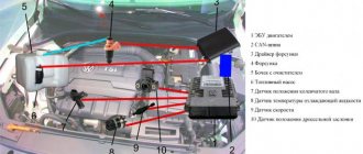
DMRV operation diagram
- The yellow wire is located closer to the windshield. It serves as an input for a signal from the flow meter.
- The white-gray wire is the sensor voltage output.
- The black and pink wire leads to the main relay.
- The green wire is used to ground the sensors, that is, it goes to ground.
The wires may have different colors, but their location is unchanged. To check, you need to turn on the ignition, but do not start the car. The red probe from the multimeter must be connected to the yellow wire, and the black one must be connected to ground, that is, to the green wire. We measure the voltage between these two outputs. Multimeter probes make it possible to connect without disturbing the insulation of the wires.
On the new device, the output voltage ranges from 0.996 to 1.01 V.
What is bit resolution and why is it important?
In the early days of data acquisition, 8-bit ADCs were common. As of this writing, 24-bit ADCs are the standard for most data acquisition systems designed to make dynamic measurements, and 16-bit is considered the minimum resolution for signals in general. There are a number of low-cost systems that use 12-bit ADCs.
Since each bit of resolution effectively doubles the conversion resolution, systems with 24-bit ADCs provide 2^24 = 16,777,216. Thus, the single-voltage input signal can be divided into more than 16 million Y-steps.
The 16,777,216 steps for a 24-bit ADC are significantly better than the maximum theoretical 65,656 steps for a 16-bit ADC. Thus, the higher the resolution, the better the shape and accuracy of the wave functions. The same applies to the time axis.
Compare 24-bit resolution (orange) and 16-bit resolution (gray)
DualCoreADC® Technology and Why It's Important
One of the long-standing engineering problems with the amplitude axis is dynamic range. For example: what if we have a signal that is usually less than 5 volts, but can sometimes fluctuate upward sharply? If we set the ADC resolution to 0-5V, the system will be completely overloaded if the signal exceeds this level.
One solution would be to have two channels set to different gains; and send 0–5 V data to one of them, and with a higher amplitude to the other. But this is very inefficient: we cannot use two channels for each input signal - this will reduce the performance of the data acquisition system by half. Data analysis after each measurement will also become more complicated and time-consuming.
DualCoreADC® technology solves this problem by using two separate 24-bit ADCs per channel and automatically switching between them in real time to create a single, continuous channel. These two ADCs always measure the high and low gain of the input signal. This ensures full measurement of the sensor range and prevents signal clipping.
Video explaining Dewesoft's DualCoreADC technology
With DualCoreADC® technology, SIRIUS data acquisition systems achieve 130 dB signal-to-noise ratio and over 160 dB dynamic range. This is 20 times better than typical 24-bit systems can provide.
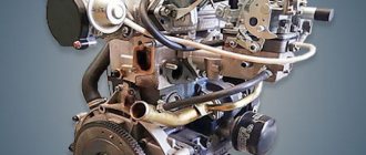
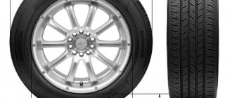
Symptoms of a problem
The mass air flow sensor is located in the air duct near the air filter. It is designed to determine the amount of incoming air. Depending on its readings, the control unit will show how much fuel is needed to form a high-quality fuel mixture. The normal ratio is 1:14. Therefore, the quality of the fuel-air mixture depends on the correct readings of the flow meter.
The high-quality operation of the mass air flow sensor depends largely on the cleanliness of the air filter. Therefore, if symptoms of a malfunction of the mass air flow sensor appear, you should first check the air filter before making repairs. The flow meter is usually beyond repair. If it is faulty, it is replaced with a new device. But its cost is quite high, so you should first make sure that the causes of the problems are in the sensor and not in other malfunctions of the machine.
The signal for diagnosis is the following symptoms of a malfunction of the mass air flow sensor:
- Check Engine appears on the instrument panel;
- an error is displayed indicating a low level of the mass air flow sensor signal;
- the engine starts poorly when cold, accelerates very slowly, stalls, and its power drops;
- high level of fuel consumption;
- the engine is unstable at idle;
- the engine stalls when changing gears;
- The rpms are either high or low.
There are other symptoms of a “dying” sensor. For example, it may have cracks in the corrugated hose that connects the throttle body to the sensor. If the engine stalls, there may be a power problem or damaged wiring. This is a signal to check the electrical wiring. If malfunctions are detected, the machine's electrical system must be repaired.