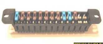
Purpose of parts on the board of the Priora electrical package control unit 2170-3763040
F1 (green) 30 Electronic engine management system F2 (blue) 60 power package control unit, engine fan, heated rear window, ignition switch relief relay F3 (blue) 60 cooling fan power supply circuit, horn, alarm, ignition switch, combination devices, interior lighting, brake light, cigarette lighter F4 (blue) 60 Generator Priors F5 (red) 50 Electromechanical power steering F6 (blue) 60 Generator
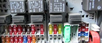
Fuse box of Lada Priora in the cabin
F1 (blue) 15 Main relay and starter interlock circuit F2 (brown) 7.5 Controller power circuit F3 (blue) 15 Electric fuel pump fuse K1 - Ignition relay K2 - Electric fuel pump relay
Lada Priora fuse box under the instrument panel
F1 25 Electric radiator fan of the cooling system F2 25 Heated rear window Priors F3 10 High beam right F4 10 High beam left F5 10 Sound signal F6 7.5 Low beam (left) F7 7.5 Low beam (right) F8 10 Alarm signal F9 25 Heater Priors F10) 7.5 Interior lighting, instrument cluster, brake light F11 20 Windshield wiper F12 10 Terminal 15 devices F13 15 Cigarette lighter F14 5 Left side light, license plate light, trunk light F15 5 Right side light F16 10 Terminal 15 ABS F17 10 Fog light (PTF) left F18 10 Fog light (PTF) right F19 15 Heated seats F31 or F27 30 Electrical package control unit
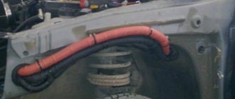
At the end of the work, all the wires are successfully hidden behind the carpet and thermal insulation. Therefore, this type of work will not affect the visual appearance of the salon.
What functions does the block provide?
The main functional purpose of the device is to monitor and control the electrical system in the car. Some important functions for which the block is responsible:
- fog lights, low beam, side lights;
- lighting in the car interior;
- direction indicators;
- power window system;
- operation, adjustment and heating of side mirrors;
- anti-theft system;
- signaling;
- door locking;
- trunk lighting;
- instrument panel lighting.
Partial, and even more so complete failure of the unit causes significant trouble for any car owner. The biggest problems are caused by the failure of the comfort unit in dense city traffic conditions.
Electromagnetic relay
An electromagnetic relay is a switching device designed to relieve contacts. The work is based on the law of electromagnetic induction.
In cars, relays are used to unload contacts on control buttons, so that they, in turn, do not melt or heat up when more current appears on them. The relay consists of moving and non-moving contacts, a DC coil, a return spring, a coil core and an armature.
Relay operating principle
When a current appears on the relay coil, a magnetic field is formed in it, which in turn begins to attract the armature to which the movable contacts of the relay are attached. As a result, the moving contacts close with the fixed ones and the electrical circuit is completed.
Replacement and repair of the electrical package control unit 2170-3763040 Lada Priora
Priora electrical package control unit 2170-3763040 (Comfort unit) The vehicle equipment, as is sometimes written, does not matter when a unit with this number is installed.
The electrical package controller is a device designed for installation on VAZ 2170 Priora cars. It controls many car functions, for example, turn signals, power windows, instrument panel lights, side lights, low beam, fog lights, reverse lamp, interior lighting, heated rear window.
This controller is installed in the central, lower part of the dashboard above the ECU unit. To remove it, you need to remove the lower sides of the torpedo. Using a socket wrench 10, unscrew the two nuts.
Priora electrical package control unit housing 2170-3763040
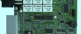
Priora electrical package control unit board 2170-3763040
Location of terminals of the Priora electrical package control unit 2170-3763040
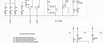
Diagram of the Priora electrical package control unit 2170-3763040
Purpose of parts on the board of the Priora electrical package control unit 2170-3763040
POS - interior lighting lamp ZPTO - rear fog lights BS - low beam PTF - fog lights MDV - driver's door module PUP - turn signal switch PAS - hazard warning switch PPD - front right door PLD - front left door ZPD - rear right door ZLD - rear left door PS - passenger door power window switch FOB - trunk light ZP - right mirror ZL - left mirror GO - side lights UP - direction indicators
Problem with the electrical package control unit 2170-3763040 Priora:
Priora electrical package control unit 2170-3763040 old
After turning on the heated rear window, a malfunction occurred in the operation of this unit. The IMMO started flashing, the emergency lights came on - it’s impossible to turn it off. After turning off the heating, the turn signals and emergency lights, mirrors stopped functioning, the central locking stopped working, both from the key and from the buttons in the cabin, the tidy went out, and the power windows stopped working.
A new electrical package control unit 2170-3763040 Priora was installed:
Electrical package control unit 2170-3763040 new
The procedure for removing and installing the block is simple. There is no need to retrain the key, everything works. The only thing is that the two-level door opening system stopped working. Now one click opens two doors. or one press and only the driver's door opens, a second press and the passenger door does not open... Strange.
Repair of the electrical package control unit 2170-3763040 Priora: In the old unit, for the sake of experiment, two VN5016AJTR-E power driver microcircuits (SSO-12) were replaced
Resoldering the VN5016AJTR-E chips did not bring any results.
Resoldered chip: MCZ33972EW
Chip MCZ33972EW for replacement.
What is a CAN bus and what is it for in Lada Priora
A modern car, unfortunately or fortunately - it’s up to you to decide, is no longer the same box on wheels with fifteen
Basket
Double-glazed window control unit “Norma” 1118 – 6512010 for VAZ 11183 “Kalina”
Aktuator On cars of the Kalina family, 2 types of non-interchangeable (by wiring) glass unit control controller 1118 - 6512010 and 11180 - 3763040 can be installed. 1118 – 6512010 has one 25-pin connection connector, 1118 – 3763040 (1118 – 3763040 – 10) – two connectors.
Remote control system for double-glazed windows “norm” on a VAZ 11183, Kalina. Controls power windows and central door locking. When the connector is removed, the engine does not start; the device performs some of the anti-theft functions.
Connection
| № | Wire color | Purpose, addressing |
| 1 |
External Shock or Volume Sensor Input (Not Used)* 2 Pink/Black To Door Lock Switch in Switch Box
3 Brown/Green K‑Line. To Kl. 71 ECM, Cl. 18 APS‑6
4 Brown Connects to ground when the driver's door is closed
5 Gray To heated rear window element
6 Black Mass
7 Pink/White To door lock switch in switch block
8 Yellow/Blue To the instrument cluster, to the APS‑6 indicator
9 Black/White Connects to ground when the hood is opened. C VK engine compartment lamp
10 Two White/Red Connects to ground when opening the rear doors
11 Brown/Red Connects to ground when opening the right front door
12 Output 12 V power supply for external sensor (Not used)*
13
Not used
14 Yellow Pulse + 12 V, closing all doors and trunk
15 Red/Blue K class. 14 APS‑6
16 Blue with Black To left direction indicator
17 Red/Blue Pulse + 12 V, opening passenger doors
18 Red/Black Pulse + 12 V, driver door open
19 Pink/Red Impulse + 12 V, opening the trunk lock
20 Yellow/Blue To terminal “15”, via fuse F 9, in the mounting block
21 Grey/Black “-” Horn relay
22 White/Blue Connects to ground when the driver's door is opened
23 Red To permanent plus through fuse F 5, in the mounting block
24 Blue To right turn signal
25 White/Black Connected to ground when opening the trunk
* A regular shock sensor from any alarm system (Alligator, Saturn, Clifford, APS) is suitable.
+ 12 V connect to pin 12; body – on the 6th; We connect the signal wire (a ground appears on it at the moment of activity) to the 1st contact.
During normal arming, Kalina now reacts to an impact on the body (it sounds a horn and blinks turn signals). Similarly, instead of a shock sensor, you can connect a volume sensor (for example, single-level MMS‑1).
You can also connect a pager: + 12 V of the pager transmitter on pin 12, minus on pin 21.
Double-glazed window control unit 1118 – 3763040 (- 10 ) for VAZ 11183 “Kalina”
| Controller board | ||
| Controller board |
| The key code is not readable |
1 . 1 Malfunction in the VZ communication coil circuit
1 . 2 Malfunction in the circuit from the block to the communication coil to the APS ECU
1 . 3 Transponder missing in OK
1 . 4 The transponder in OK is faulty (detected during pre-production preparation)
1 . 5 The transponder in the Republic of Kazakhstan is faulty (detected during pre-production preparation)
1 . 6 Malfunction of the input transponder circuit in the APS ECU
1 . 8 The communication coil came off from the VZ pad on the inside
1 . 1 - replacement 1118 – 6105006 (set) - rearrange the transponder - rearrange the remote control 1. 2 - replacing the instrument panel harness 1. 3 -replacement of KSUD -replacement of 1118 – 6105006 (set) -replacement of remote control -train the system 1. 4 - rearrange the transponder (if there is a clean one) otherwise: - replace 1118 – 6105006 (set) - retrain the system 1. 5 - replace the remote control - train the system 1. 6 - replace the faulty unit - train the system 1. 7 - replace the remote control with a “clean” one - train the system 1. 8 - replace 1118 – 6105006 (set) - rearrange the transponder - rearrange the remote control
What kind of engine does the Lada X-Ray have?
2. 1 Check the continuity of the circuit 2. 2 Trial one-by-one replacement of blocks with known good ones 2. 3 1. Check V on KSUD: room No. 12; room No. 13; room No. 44 and room No. 63 2. Check V on the APS: room No. 6; room No. 16; room No. 20 2. 4 Remove the block from the “Norma”, if the fault has disappeared and the internal combustion engine starts, then the electrical package is faulty. Carry out a test replacement of the “Norma” electrical package 2. 5 Check that the coolant is getting into the KSUD (Kalina) 3 sound signals IC flashes 3 . 1 APS ECU – “alien” 3. 2 OK – “foreign” 4 beeps IC lights up constantly The system is not trained - train the system
The KSUD was previously trained with another system. Very rare reason: the IS is blinking, there are no sound signals. The APS is trained, but the KSUD is “clean” - retrain the system
Abbreviations: IS – status indicator; VZ – ignition switch; OK – training key; RK – working key; RC – remote control; KSUD – engine control system controller; ECU - electronic control unit
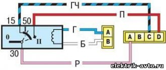
Ignition system diagram Lada Kalina Lux
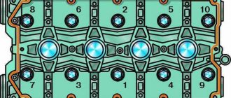
1 — oil pressure warning lamp sensor;
2 — coolant temperature indicator sensor; 3 — additional fuse block; 4 — fuses for the electric fan of the engine cooling system; 5 — electric fuel pump relay; 6 — relay for the electric fan of the engine cooling system; 7 - ignition relay; 8 — relay 2 of the electric fan of the engine cooling system; 9 — relay 3 of the electric fan of the engine cooling system; 10 — electric fan of the engine cooling system; 11 — throttle position sensor; 12 — idle speed regulator; 13 — coolant temperature sensor; 14 — diagnostic block; 15 — ignition system harness block to the instrument panel harness block; 16 — solenoid valve for purge of the adsorber; 17 — speed sensor; 18 — ignition system harness block to instrument panel harness block 2; 19 — mass air flow sensor; 20 — crankshaft position sensor; 21 — oxygen sensor; 22 - controller; 23 — rough road sensor; 24 — diagnostic oxygen sensor; 25 — ignition coil harness block to the ignition system harness block; 26 — ignition coils: 27 — ignition system harness block to the ignition coil harness block; 28 — spark plugs; 29 — nozzles; 30 - resistor; 31 — air conditioning system pressure sensor; 32 — blocks of the ignition system harness and injector wiring harness; 33 - phase sensor; 34 - knock sensor. Ignition system wiring harness -11184-3724026-10. Ignition coil wiring harness -1118-3724148-00. Injector wiring harness -11184-3724036. A - to the “plus” terminal of the battery.
Malfunctions in the operation of the comfort unit, how to eliminate them
- The turn signals do not light up. First, you should check the continuity of the fuse, lamps and steering column switch. If there is simply no contact somewhere, then the problem can be resolved very simply by resoldering the microcontacts. If there is a fault in the board itself and soldering the contacts does not help, then the controller should be replaced.
- The power window module or central locking does not work. This problem can also occur due to oxidation of the wires. Before removing the comfort unit, you need to check all the wires with a multimeter under the insulation in the control unit, which is built into the driver's door. If only one glass unit is faulty, the wires could become disconnected due to a broken contact.
After checking the wires, if the problem cannot be found. The DA7VN5016A or DA6VN5016A controller should be re-soldered. One of them is responsible for the double-glazed windows and the lock on the right door. The second mirrors the same functions, but on the left side.
Sometimes window lifters only work to lower the windows, but raising them is not available (or vice versa). To do this, check the connection so that all the pros and cons are in place.
Errors occur in the comfort unit when the window lift button to raise the window works to lower the window. With different polarities, when the glass rises instead of lowering, you need to change the connection of two adjacent wires.
- It happens that many problems arise at the same time. The fog lights, side lights, rear lights, heated rear glass, and interior light stop working. In this case, it is obvious that the problem comes from the comfort unit and the DA1 MC33972EW variant is re-soldered. If this does not help, then the entire circuit should be replaced.
- In case of failure of the rear fog lights and instrument lighting in the cabin, the DA9 VND5025AK component is re-soldered. And, as was the case with previous breakdowns. If this does not bring results, the entire scheme is changed.
- The central locking locks begin to operate when the power window keys are pressed. If replacing the comfort unit from another car does not bring any effect, then the essence of this breakdown is in the wiring. To do this, you need to carefully check the integrity of all wires leading to the comfort unit.
Possible causes of malfunctions
Before purchasing a new comfort unit, you need to try to eliminate any malfunction. In order not to make additional costs, because the comfort unit is quite expensive. Often the problem is simply a lack of contact due to aging or chafing of the wires.
Sometimes the comfort unit controllers can burn out, for this you need to inspect them visually or even check them using your sense of smell.
The most common complaints regarding the operation of the comfort unit are the failure of double-glazed windows, turn signals or dimensions.
All problems can occur due to the following events
- break on the W-Line communication line;
- combustion of regulation drivers;
- burnout of controllers responsible for the desired area;
- transponder malfunction;
- burnout or oxidation of contacts.
Before carrying out repair work, to comply with safety precautions, do not forget to disconnect the negative terminal from the battery.
Fuse
A fuse is an electrical switching device designed to protect electrical circuits by breaking the circuit due to its destruction or shutting down when a current flowing through it exceeds the permissible values.
Fuses come in several types and are used in all electrical circuits to protect vehicles from short circuits (short circuits). They are classified according to the rated current of the fuse link.
The fuse link is the part of the fuse that is destroyed by electrical current.
The rated current is the current of the fuse at which the fuse-link will operate indefinitely and will not be subject to destruction.
Operating principle of the fuse
When using a fuse in an electrical circuit, the operating current passing through the fuse does not exceed its rated current - this is its normal operation. But as soon as a current appears in the electrical circuit that exceeds the safe permissible values in this circuit, regulated by the fuse, the fuse-link, under the influence of a current exceeding the rated current of the insert, begins to melt and collapse as a result of which the electrical circuit breaks.
You can restore the electrical circuit by replacing the fuse, but only after the culprit for the increased current in this electrical circuit has been found. Otherwise, the new fuse will also blow.
Where is the Priora comfort block located?
To gain access to the product, you will need to unscrew the protective plastic walls of the car's center console. They are located on the left side of the front passenger seat and on the right of the gas pedal, on the driver's side. The device itself is located above the control unit. In order to remove the device you will need a 10 mm wrench and a Phillips screwdriver.
Pinout of the Priora comfort block
The main, important elements of the device are:
- The so-called control drivers. Each driver is responsible for a set of specific functions.
- Transponder receiver.
- Relay control.
- Transceiver. Communicates with the module installed in the door.
- 2 connectors. The first is responsible for supplying power, the second for transmitting the necessary technical information.
Click to enlarge
To ensure proper operation of all elements connected to the comfort unit connectors, it is necessary to study the correct pinout (numbered diagram for connecting wires to contacts). The design of the comfort block for the Priora, when studied in detail, is not particularly difficult.
Glass closer Pandora DWM
Connection diagram for the passenger door button in series through a duplicate button on the driver's door. Contacts 1-6 and 7-3 are always normally closed. When you press the up button, contacts 1-6 open and 1-2 close (window rises). When you press the down button, contacts 7-3 open and 7-2 closes (window down). The 30th contact of a 5-pin relay, without supplying voltage to the winding contacts, is constantly shorted to contact 88, which gives us the necessary negative contact (works like a switch). If voltage is applied to the winding, then contact 30 is disconnected from contact 88 and connected to contact 87. Contact 86 of the winding is connected to ground.
Possible malfunctions and ways to eliminate them
What malfunctions may occur in the operation of the electrical package controller:
- Turn signal failure. First of all, you need to diagnose the serviceability of the fuse, light bulbs, and the steering column switch. It is quite possible that the contact in the switch itself is broken; the problem can be solved by resoldering the contacts or replacing it. If this does not help and the problem really lies in the board, then there are two options - either resoldering it in accordance with the diagram, or replacing it. Usually, soldering is done first, and if it does not help, then the controller itself is changed.
- The power windows don't work. Before getting into the circuit, you need to make sure that the problem does not lie in other elements. As in the previous case, first check the fuse, and then diagnose the power window control unit, it is built into the driver's door trim. If only one window regulator does not work, then most likely the contact on the unit has simply come loose and needs to be reconnected. Sometimes the problem lies in a broken or broken wire, in which case the circuit needs to be restored. If this does not help, then the DA7VN5016A or DA6VN5016A controller is resoldered. The first is responsible for the operation of the power windows and central locking on the right doors, and the second is responsible for the same elements, only on the left door. Both elements are marked in the diagram for clarity. The problem with the central locking is solved in a similar way if it does not work. Also pay attention to the DA11L9848 controller - it is responsible for the operation of the lift control relay. So if the relay does not work, but the contacts of its seat are intact, then perhaps the problem lies with this controller.
- At the same time, the side lights, front and rear fog lights, interior lights, reversing lights, and the rear window heating system stopped working. If these components stop working at the same time, then there is no doubt that the problem lies in the electrical package control unit. In this case, the DA1 MC33972EW controller is resoldered, since it is he who is responsible for the operation of these components. If resoldering does not help, then the entire circuit changes.
- If the rear fog lights and the dashboard lights do not work, then most likely the culprit is the DA9 VND5025AK controller. You can also try to re-solder this component, but if re-soldering does not produce results, then it will need to be completely changed.
Installing rear door lifts
Electric windows are a necessary element of comfort. But with Priora everything is not so simple. Standard wiring (unless, of course, you have a luxury version) is not enough to install lifts in the rear doors. And the first thing you have to do is stretch the necessary wires from the control unit to the doors. Moreover, this is not the only difficulty. On some versions without rear ESPs, relays for them are installed, and the control unit has only 2 buttons. Thus, in order to install the lifts back, you need to change the control unit to a four-button one.
When replacing the unit, problems may arise with the immobilizer of the standard anti-theft system. It must either be deactivated or reprogrammed. It depends on whether you want a factory alarm. In general, the procedure, which in itself is not too complicated, becomes more and more complicated in Priora trim levels other than the luxury one.
In order to install electric windows on a Priora, you will need a set of keys, the lifts themselves and a screwdriver. Time spent from 15 minutes on the door without taking into account fiddling with the immobilizer. In some cases, up to five hours of work will be required.
But even a seemingly correct installation does not guarantee that the Priora’s power windows will immediately start working.
The Priora has a rather complex wiring diagram, especially for those who have not done any manipulations with it before. And if there are no relays in the rear doors yet, you will have to purchase and install them.
By the way, it’s easy to check their presence: when you use the window regulator on the front door, quiet clicks will be heard in the rear ones. These are working rear relays, quite suitable for installing non-standard ESPs compatible with your car. There is some information on this issue on car forums.
You also need to know how to remove the lift to replace or repair it. Everything is simpler here, we take out the glass, disconnect the electric motor connector, use a ten key to unscrew the fasteners and pull out the mechanism itself through a specially provided hole. And so with every door. The casing must be removed before starting work.
The window regulator on the Priora in the Norma configuration is installed in its regular place. Next, you need to connect the rear door buttons, taking into account that each of the buttons has 3 contacts (for power, ground and common wire). The wires from contacts 1 and 3 must be led independently to the control unit under the dashboard. The common wire is connected to one of the wires coming from the controller. After these operations, we connect each Priora lift with an electric motor.
To connect an electric drive to the lift, you first need to remove the power connector from the controller. There are just two empty nests in it. You just need to remove the clamp to easily connect the wires necessary for the operation of the lifts. You also need to run the wires into the corresponding connectors of the rear doors (their colors are red and black). The easiest way to stretch them is along the original wiring of the VAZ Priora. The blog drive2.ru has detailed instructions on this point with photographs. In general, Priora window regulators are quite simple to install and dismantle.
Self-repair of the Priora comfort unit, is this possible?
If you have never encountered soldering, diagnostics of printed circuit boards of varying complexity and configurations, or do not have the necessary diagnostic or soldering equipment, then it is better to address the repair question to qualified specialists. If you have the above skills and understand the causes of malfunctions, independent repairs are carried out quite often. This is due to the fact that various microcircuits or chips constantly fail. For example, having established that the reason for the turn signal failure is a failed control driver, it is always possible to purchase a new part and simply re-solder it to replace the faulty one.
Malfunctions and their possible causes
The cost of a new, original unit is quite high, so do not rush to buy a new product, figure out the causes of the malfunctions. Of course, there are always cases when the board cannot be repaired and it is more advisable to simply install a new product to replace the faulty one. Do not forget that the causes of malfunctions can be frayed or broken wires that are connected to energy consumers.
According to statistical data collected on technical support forums, car owners quite often complain about malfunctions in the operation of power windows, turn signals, and parking lights.
If we talk about the components of the printed circuit board itself, the most common breakdowns are associated with: - a break in the W-Line communication line; — burnout of control drivers; — burnout of controllers responsible for correct operation; - the output of their transponder; — significant oxidation of contacts.
"Important! Before carrying out any electrical work, disconnect the power supply by disconnecting the negative terminal of the battery."
Schematic diagram (pinout) of connecting the front wiring harness on the Priora
The front part of the vehicle's electrical circuit is designed to supply voltage to the primary and auxiliary power circuits of the vehicle's on-board systems. The decoding of contact group chips is as follows:
- 1 – starter power supply;
- 2 – battery;
- 3 – charge supply from the generator;
- 4 – connecting block for the bundle (1 – 3);
- 5-7 – power supply to the device;
- 8 – engine compartment lighting lamp;
- 9-10 – head light;
- 11 – brake expansion tank level indicator;
- 12 – outside temperature;
- 13 – washer drive;
- 14 – external indication of reverse gear;
- 15 – cooling system fan;
- 16 – stove reducer;
- 17 – reserve resistor;
- 18 – wiper drive;
- 19 – interior relay and fuse module;
- 20 – stove motor;
- 21 – sound alarm indicator;
- 22 – horn power supply;
- A1/2, B1/2 – mass.
How to enable self-diagnosis of the instrument panel
On-board computer staff Priora matrix instead of a clock in the console from the Lada Priora
Using the panel you can “dig into the brains” of the Priora:
- Hold the button under the fuel gauge and turn on the ignition. The display should indicate the start of the test.
- Press the button again. The display should show the operating system version.
- Click again. The system should show error codes:
- (2) – High voltage level;
- (3) – DT malfunction;
- (4) – DTOZH malfunction;
- (5) – DTV malfunction;
- (6) – Motor overheating;
- (7) – Low oil level;
- (8) – Malfunction of the brake system;
- (9) – Battery discharge;
- E – Brain error, EEPROM.
- If necessary, reset the error: hold the button for three seconds.
- Release the button. Click again. All indicators should light up.
- Leave all the buttons. After 30 seconds, the self-test will automatically complete.
The dashboard contains the following parts, without which the car would not function:
- external lighting controller;
- switch for turning and lighting headlights;
- signal regulator;
- instrument cluster;
- wiper regulator.
Types of compatible window regulators
One of the most common models on the aftermarket is the window regulator for the Priora Forward. This model of electric lift is made in a combined arrangement of the drive and the actual rack-and-pinion lifting mechanism, compactly combined with the glass guide. Lifts of this model are characterized by increased reliability and ease of installation on Priora.
Garnet is the second most popular system. Under this name there is not even a single model, but a whole family, each modification of which is intended for a specific car. The mechanism is also rack and pinion type and has earned many good reviews from car enthusiasts. This type of lifts is characterized by uninterrupted operation, fast speed of raising/lowering the glass, and low noise.
It has already been said above about glass closers. In the luxury package they are available on all doors, but their performance leaves much to be desired. It is necessary to resort to replacement with other similar devices. One of the available alternatives is the Master system. It allows you to automatically raise the windows when the anti-theft system is turned on, and even control them within half an hour from the moment the ignition is turned off. The device itself looks like an electronic board with connectors connected to the standard Priora wiring.
The master is not very expensive (from 700 rubles), and its installation does not affect the door trim in any way. The whole procedure consists of removing the rear door sill trims, bending the sound insulation and connecting the door closer to the connector.
For the front doors, the Master will by default raise and lower the windows without ignition, and for the rear doors you need to install a slightly different version, called Master Plus. There are no differences in installation, the main thing is not to forget to disconnect the negative battery before starting work. The wizard has many other useful functions, for example, it automatically turns off the radio when the car is armed.
Location of the comfort controller in the cabin
You need to know that there are two options for the location of this device:
- On the first Priora models it is under the beard.
- On subsequent ones, to the left of the mounting block.
When these cars appeared, the comfort unit was installed in the area of the electronic control unit. That is, under the “beard”. If you open the decorative plastic cover located at the passenger’s left foot, you will see the Priora control unit with attached relays. Directly above them is a comfort unit (electrical package).
On subsequent cars this unit was positioned slightly differently. At the driver's left foot, with the instrument panel cover removed under the steering wheel, there is a fuse and relay assembly. Or - a mounting block. And behind it, at the wall of the body, the electrical package is mounted. Access to it is quite difficult.
Removing the comfort block on new models
If you follow the manufacturer's technological instructions, this is a very complex and time-consuming process. Suffice it to say that according to this scheme it is necessary to partially dismantle the entire dashboard of the Priora. Of course, experienced locksmiths do not do this. The process goes as follows. The negative terminal of the battery is removed.
After this, remove the decorative panel under the steering wheel. It is secured at the bottom with 3 plastic swivel fasteners. The mounting block will become available. Now comes the most difficult part. You will need a 10mm bell key. This is the most convenient option for this job.
You'll have to climb and grope with your hand. As already mentioned, the electrical package controller is screwed behind the mounting one. It is perpendicular to it. It is secured with two bolts
heads 10. Before unscrewing them, you need to disconnect the three wiring harnesses connected to the block. It is not difficult. And it is impossible to confuse them during installation. They have different entry options. After this, you can remove the mounting bolts. Since the ears on the device are not closed, but have a free exit, one of the bolts can only be loosened 3-4 turns. And then take out the block.
Install the new one in the same way.
Replacement on the first Priors
This is generally a simple operation. The shield is removed from the bottom of the “torpedo” on the passenger side. The comfort controller is perfectly accessible. Unscrew the fasteners in the same way and remove the device. Replace with new one. The only thing is that the wiring harnesses are on the driver's side. But it is just as easy to remove the side panel, which is secured with 1 bolt.
The main functions performed by the electrical package control unit (comfort unit)
In fact, this device is a multifunctional control computer. His responsibilities include ensuring the functionality of many Priora functions:
- Electric windows.
- Adjusting the side mirrors.
- Turn and hazard warning lights.
- Anti-theft system.
- Door locking from the driver's door remote control.
- Lighting module.
So many options require precise operation of the Priora comfort controller.
Replacing the Priora comfort unit
Before purchasing a new product, you must be sure that the cause of the malfunction lies precisely in it. To do this, you can install a known-good unit in your car and test the operation of problematic units. If, with a new, serviceable device, electrical consumers operate normally, the old comfort unit is faulty. Otherwise, use an integrated approach, check fuses, relays, wiring, and all kinds of drives. In other words, the entire technical chain with which the faulty unit usually comes into contact during operation.
Replacement of the device is carried out in 7 simple steps:
- We put the car on the parking brake.
- Open the hood, loosen the negative terminal and remove it from the battery.
- We move into the car interior. For ease of operation, we roll the front seats back into the cabin as far as possible.
- We prepare the tool. Using a screwdriver, unscrew the mounting bolts and remove the 2 side walls.
- Using a 10mm wrench, unscrew the two fastening nuts.
- Carefully remove the block itself. When removing, rotate the product so that it does not hit other elements. Disconnect two contact connectors, the first is power, the second is information.
- Remove the faulty product and install a new one.
In the future, in order to inspect, diagnose or repair the Priora comfort unit, you will need to remove its protective housing. When purchasing a new unit, keep your sales or sales receipt. If you purchase a faulty device, this will allow you to return or exchange it for a new one. Prices for the product vary depending on the specific seller and range from 2,500 rubles to 10,000 rubles.
Central lock VAZ 2114 Central lock VAZ 2114 (hereinafter referred to as CZ) is a mechanism018.8k.Electrical equipment
Replacing the ignition module on a Granta The ignition module of the Lada Granta is an important component012.1k.Miscellaneous
Heater cables VAZ 2114 Winter has come and you are looking forward to a comfortable and warm trip211.5k.Electrical equipment
Cooling fan Priora Cooling fan Priora is the most important element010.6k.Electrical equipment
Turning relay on Grant It happens that during the operation of the car 010.1k. You may also like
TPS on Priora Modern cars are controlled and controlled06k.
Crankshaft sensor Lada Priora A car is a collection of complex interacting components03.1k.
How to start a Priora without an ignition key You are the owner of a Priora and don’t know how to start it03.4k.
Rain sensor on the Priora The rain sensor (on the Priora) is an automotive element04.7k.
Cooling fan Priora Cooling fan Priora is the most important element010.6k.
Phase sensor for Lada Priora Phase sensor for Lada Priora or distribution position 02.9k.
Clutch sensor on Priora The popular “Priora” is designed in the spirit of the times04.2k.
Eliminating heater noise on a Priora The heater of modern cars works well enough15.9k.
Replacement of the Lada Priora comfort unit. Pinout and repair
The electrical package control unit, or the so-called Priora comfort unit, is a complex electrical device. Its basis is a printed circuit board with numerous microcircuits, relays, control drivers and other elements soldered to it.
The control unit (hereinafter referred to as the product) is installed directly in the car, so its components (microelectronics) are exposed to negative influences. For example: cold, active shaking, temperature changes. As a result, certain elements burn out on the board, the integrity of the contact group is disrupted, which leads to the failure of many vehicle functions important for the daily operation. Unfortunately, in many Lada Priora cars, failure of the electrical package control system has become a fairly common occurrence.
What functions does the block provide?
The main functional purpose of the device is to monitor and control the electrical system in the car. Some important functions for which the block is responsible:
- fog lights, low beam, side lights;
- lighting in the car interior;
- direction indicators;
- power window system;
- operation, adjustment and heating of side mirrors;
- anti-theft system;
- signaling;
- door locking;
- trunk lighting;
- instrument panel lighting.
Partial, and even more so complete failure of the unit causes significant trouble for any car owner. The biggest problems are caused by the failure of the comfort unit in dense city traffic conditions.
Where is the Priora comfort block located?
To gain access to the product, you will need to unscrew the protective plastic walls of the car's center console. They are located on the left side of the front passenger seat and on the right of the gas pedal, on the driver's side. The device itself is located above the control unit. In order to remove the device you will need a 10 mm wrench and a Phillips screwdriver.
Pinout of the Priora comfort block
The main, important elements of the device are:
- The so-called control drivers. Each driver is responsible for a set of specific functions.
- Transponder receiver.
- Relay control.
- Transceiver. Communicates with the module installed in the door.
- 2 connectors. The first is responsible for supplying power, the second for transmitting the necessary technical information.
Click to enlarge
To ensure proper operation of all elements connected to the comfort unit connectors, it is necessary to study the correct pinout (numbered diagram for connecting wires to contacts). The design of the comfort block for the Priora, when studied in detail, is not particularly difficult.
Self-repair of the Priora comfort unit, is this possible?
If you have never encountered soldering, diagnostics of printed circuit boards of varying complexity and configurations, or do not have the necessary diagnostic or soldering equipment, then it is better to address the repair question to qualified specialists.
If you have the above skills and understand the causes of malfunctions, independent repairs are carried out quite often. This is due to the fact that various microcircuits or chips constantly fail.
For example, having established that the reason for the turn signal failure is a failed control driver, it is always possible to purchase a new part and simply re-solder it to replace the faulty one.
Malfunctions and their possible causes
The cost of a new, original unit is quite high, so do not rush to buy a new product, figure out the causes of the malfunctions. Of course, there are always cases when the board cannot be repaired and it is more advisable to simply install a new product to replace the faulty one. Do not forget that the causes of malfunctions can be frayed or broken wires that are connected to energy consumers.
According to statistical data collected on technical support forums, car owners quite often complain about malfunctions in the operation of power windows, turn signals, and parking lights.
If we talk about the components of the printed circuit board itself, the most common breakdowns are associated with: - a break in the W-Line communication line; — burnout of control drivers; — burnout of controllers responsible for correct operation; - the output of their transponder;
— significant oxidation of contacts.
"Important! Before carrying out any electrical work, disconnect the power supply by disconnecting the negative terminal of the battery."
Replacing the Priora comfort unit
Before purchasing a new product, you must be sure that the cause of the malfunction lies precisely in it. To do this, you can install a known-good unit in your car and test the operation of problematic units. If, with a new, serviceable device, electrical consumers operate normally, the old comfort unit is faulty. Otherwise, use an integrated approach, check fuses, relays, wiring, and all kinds of drives. In other words, the entire technical chain with which the faulty unit usually comes into contact during operation.
Replacement of the device is carried out in 7 simple steps:
- We put the car on the parking brake.
- Open the hood, loosen the negative terminal and remove it from the battery.
- We move into the car interior. For ease of operation, we roll the front seats back into the cabin as far as possible.
- We prepare the tool. Using a screwdriver, unscrew the mounting bolts and remove the 2 side walls.
- Using a 10mm wrench, unscrew the two fastening nuts.
- Carefully remove the block itself. When removing, rotate the product so that it does not hit other elements. Disconnect two contact connectors, the first is power, the second is information.
- Remove the faulty product and install a new one.
In the future, in order to inspect, diagnose or repair the Priora comfort unit, you will need to remove its protective housing. When purchasing a new unit, keep your sales or sales receipt. If you purchase a faulty device, this will allow you to return or exchange it for a new one. Prices for the product vary depending on the specific seller and range from 2,500 rubles to 10,000 rubles.
Sources
- https://ladaservice.info/lada-priora/elektroborudovanie/blok-komforta-lada-priora/
- https://aforizmus.ru/blok-komforta-priora/
- https://avznn.ru/tyuning/raspinovka-elektropaketa-priora.html
- https://moto-sol.ru/diagnostika-i-remont/blok-komforta-priora-gde-nahoditsja.html
- https://x-log.ru/blok-komforta-priora/
- https://kamaz1981.ru/vaz/remont-i-zamena-bloka-komforta-na-vaz-lada-priora-svoimi-rukami-instrukcii-po-remontu-i-zamene-bloka-komforta-na-avto- vaz-lada-priora.html
- https://AlanSpb.ru/drugoe/blok-upravleniya-elektropaketom.html
- https://otdelka-remont.ru/blok-komforta-priora-remont-svoimi-rukami/
- https://automotocity.com/avtovaz/zamena-bloka-komforta-na-priore.html
- https://arz-velolife.ru/priora/kak-snyat-blok-komforta-na-priore.html
- https://automall66.ru/kak-snyat-blok-komforta-na-priore/
[collapse]
CBKE errors
- * there is no fault code in TsBKE 21900-3840080-10;
- If an “active” fault code is detected, perform the checks outlined in the “diagnostics” column;
- After troubleshooting, clear fault codes using a diagnostic tool.
Deciphering fault codes
:
- B1002 Open in driver lock control circuit
- B1004 Open in the front left window control circuit
- B1006 * Open in the rear left window control circuit
- B1008 Open in the alarm sound control circuit
- B1010 Open in the trunk gear motor control circuit
- B1012 Open in the passenger lock control circuit
- B1014 Open in the front right power window control circuit
- B1016 * Open in the rear right window control circuit
- B1017 ROM checksum error of the central unit of body electronics
- B1018 Short circuit in the rear window heating relay coil circuit
- B1019 Short circuit in the windshield heating relay coil circuit
- B1020 Short circuit in the seat heater relay coil circuit
- B1021 Wiper malfunction
- B1023 Short to ground or overheating in the control circuit of the common board bus
- B1027 Malfunction of the power window control keys in the passenger doors
- B1028 * Short to ground in the rain sensor sensitivity regulator circuit
- B1030 Open circuit (lamp burnout) of daytime running lights
- B1031 * Open circuit in the rain sensor sensitivity regulator circuit
- B1033 Open (lamp burnout) in the left turn signal circuit
- B1034 Open (lamp burnout) in the right turn signal circuit
- B1040 Open or short to ground in the low beam headlight relay coil circuit
- B1041 * Short circuit in the automatic lighting control relay coil circuit
- B1042 Short circuit in the high beam relay coil circuit
- B1043 Short circuit in the low beam relay coil circuit
- U1044 Lack of communication with MDV
- U1045 Communication error with MDV
- U1046 * Communication error with rain and light sensor
- U1047 * No communication with rain and light sensor
- U1048 CAN bus fault
- B1049 High voltage on-board network
- B1050 Low voltage on-board network
- B1051 * Short to ground in the right mirror control circuit
- B1052 * Left Mirror Control Circuit Malfunction
- B1057 Internal malfunction of the MDV
Also using this program you can configure the central unit of the body electronics.
Set the delay for turning on the wipers after the washer is activated (from 0 to 2.56 sec).
Activate or deactivate the function of turning on the interior lamp when the ignition is turned off
Set the delay for turning off the interior lamp when closing the door (from 0 to 60 sec)
Set the delay of the energy saving mode (power loss on the interior lamp, trunk, control wire of the radio (Kalina 2) (from 0 to 10 min)
Activate or deactivate the stepwise door unlocking mode, as well as the automatic door unlocking mode when the ignition is turned off
Activate or deactivate the automatic mode of raising/lowering the driver's window
More details about the TsBKE block are described in Technological Instructions (TI) 3100.25100.12051, which you can download here.
All reference information on models
:
- Lada Granta
- Lada Kalina
- Lada Priora
Keywords: Lada Priora windshield wipers | windshield wipers for Lada Granta | windshield wipers Lada Kalina | heating for Lada Granta | heating Lada Kalina | heating for Lada Priora | external lighting for Lada Granta | external lighting for Lada Priora | external lighting for Lada Kalina | interior lighting for Lada Granta | interior lighting for Lada Kalina | interior lighting for Lada Priora | window lift for Lada Kalina | window regulator for Lada Granta | Lada Priora window regulator
5
Found an error? Select it and press Ctrl+Enter..