The crankshaft (crankshaft) is an important component in the crank mechanism of a car. Its function is to sense the reciprocating motion of the pistons and convert it into torque, thus ensuring smooth engine operation. Structurally, it consists of several main and connecting rod journals connected to each other by cheeks. As wear occurs, the shaft is ground to repair dimensions, which accordingly changes the dimensions of the crankshaft journals. Usually up to 6 repair sizes are provided; Soviet standards allowed 8 for a number of models.
What are the repair dimensions of crankshafts for? - AutoDoza - Automotive portal
The crankshaft is made of either cast iron or alloy steel; both materials are quite strong, but defects still arise over time, and repair dimensions of the crankshafts are needed to eliminate them.
These are peculiar tolerances to which the thickness of the necks can be reduced without severely compromising the strength of the part. And, since the journals usually interact with the bearings, the latter are provided with liners with repair reduction. First of all, let's look at the different types of defects that occur, as well as the reasons for their occurrence. If the geometry of the seats for the support bearings of the block is broken, rapid wear of the journals should be expected. In other words, if this process is observed, the reason is most likely exactly the same as indicated above, or in the poor quality of the material of the shaft itself. Due to poor-quality oil or its irregular replacement, scuffs may appear on the necks; a clogged oil filter, or, which is even worse, low pressure in the system, can also be the source of this trouble.
There are two types of crankshaft journals - support and connecting rod. The latter, as the name implies, are designed to transmit the translational movements of the connecting rod to the knees, thus transforming them into torque. In essence, this is the principle of a well gate, or more precisely, its curved handle, in relation to which the human forearm can be considered a connecting rod. In a standard engine, the dimensions of the crankshaft journals correspond to 47.8 millimeters. It is logical that both the bearings and connecting rod rings are also adjusted to this size. However, the sports type of crankshaft is an exception; its journals have a diameter of only 43 millimeters, which means it requires special bearing shells and the installation of appropriate connecting rods.
When you are planning to grind the shaft journals, take care of the inserts in advance; during the first repair, they can be used with a reduction of 0.25 millimeters. If necessary, subsequent repair dimensions of the crankshaft journals can be changed to 0.5, 0.75 and 1 millimeter; the corresponding liners must also be purchased. Subsequent grinding is associated with a direct risk of shaft destruction during operation; for this reason, liner sizes 1.25 and 1.5 are extremely difficult to find.
Installation dimensions of liners
KAMAZ main bearing shells
| N | Item number | Dimensions |
| 1 | 7405-1000102 No. | F int 95.00 F out = 100.00 |
| 2 | 7405-1000102 P01 (-0.25) | F int 94.75 F out = 100.00 |
| 3 | 7405-1000102 P1 (-0.50) | F int 94.50 F out = 100.00 |
| 4 | 7405-1000102 P02(-0.75) | F int 94.25 F out = 100.00 |
| 5 | 7405-1000102 P2 (-1.00) | F int 94.00 F out = 100.00 |
| 6 | 7405-1000102 P3 | F int 95.00 F out = 100.50 |
| 7 | 7405-1000102 P4 (-0.50) | F int 94.50 F out = 100.50 |
| 8 | 7405-1000102 P5 (-1.00) | F int 94.00 F out = 100.50 |
| 9 | 7405-1000102 P6 (-1.50) | F int 93.50 F out = 100.00 |
| 10 | 7405-1000102 P7 (-2.00) | F int 93.00 F out = 100.00 |
| 11 | 7405-1000104 No. | F int 80.00 F out = 85.00 |
| 12 | 7405-1000104 P01 (-0.25) | F int 79.75 F out = 85.00 |
| 13 | 7405-1000104 P1 (-0.50) | F int 79.50 F out = 85.00 |
| 14 | 7405-1000104 P02 (-0.75) | F int 79.25 F out = 85.00 |
| 15 | 7405-1000104 P2 (-1.00) | F int 79.00 F out = 85.00 |
| 16 | 7405-1000104 P3 | F int 80.00 F out = 85.50 |
| 17 | 7405-1000104 P4 (-0.50) | F int 79.50 F out = 85.50 |
| 18 | 7405-1000104 P5 (-1.00) | F int 79.00 F out = 85.50 |
| 19 | 7405-1000104 P6 (-1.50) | F int 78.50 F out = 85.00 |
| 20 | 7405-1000104 P7 (-2.00) | F int 78.00 F out = 85.00 |
YaMZ main bearing shells
| N | Item number | Dimensions |
| 1 | 236-1000102 No. | F int 110.00 F out = 116.00 |
| 2 | 236-1000102 P1 (-0.25) | F int 109.75 F out = 116.00 |
| 3 | 236-1000102 P2 (-0.50) | F int 109.50 F out = 116.00 |
| 4 | 236-1000102 P3 (-1.25) | F int 109.25 F out = 116.00 |
| 5 | 236-1000102 P4 (-1.50) | F int 109.00 F out = 116.00 |
| 6 | 236-1000102 P5 (-1.75) | F int 108.75 F out = 116.00 |
| 7 | 236-1000102 P6 (-2.00) | F int 108.50 F out = 116.00 |
Inserts 238-1000102 of all sizes correspond to the installation dimensions for 236-1000102
Inserts 238-1000104 of all sizes correspond to the installation dimensions for 236-1000104
Inserts 240-1000104 of all sizes correspond to the installation dimensions for 240-1000104
| N | Item number | Dimensions |
| 1 | 840-1000102 No. | F int 117.00 F out = 125.00 |
| 2 | 840-1000102 P1 (-0.05) | F int 116.95 F out = 125.00 |
| 3 | 840-1000102 P2 (-0.25) | F int 116.75 F out = 125.00 |
| 4 | 840-1000102 P3 (-0.50) | F int 116.50 F out = 125.00 |
| 5 | 840-1000104 No. | F int 90.00 F out = 95.00 |
| 6 | 840-1000104 P1 (-0.05) | F int 89.95 F out = 95.00 |
| 7 | 840-1000104 P2 (-0.25) | F int 89.75 F out = 95.00 |
| 8 | 840-1000104 P3 (-0.50) | F int 89.50 F out = 95.00 |
how to install crankshaft half rings
KamAZ 740 crankshaft, Characteristics of the KamAZ 740 crankshaft and repair dimensions.
Peugeot 405 1.6 XU5JP Logbook New piston rings and repair of crankshaft thrust half-rings
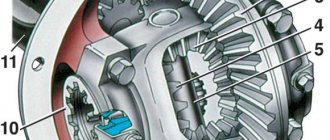
The KamAZ 740 crankshaft is made of high-carbon steel by hot stamping and is also strengthened by nitriding or hardening with high frequency currents (HFC). The connecting rod and main journals are subjected to hardening. The KamAZ 740 crankshaft has four connecting rod journals and five main bearings that connect the jaws. The crankpins of the shaft are made in such a way that they have cavities inside that are closed with plugs. The cavities are designed for additional oil purification through centrifugal forces.
To balance the centrifugal forces, counterweights are installed on the so-called nose (the front end of the crankshaft) and the shank (the rear end of the crankshaft), which on the cheeks are integral with the shaft, and are pressed onto the nose at the time of assembly and secured using a segment key.
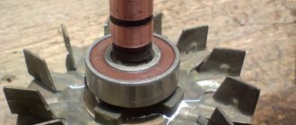
The oil pump drive gear is fixed at the front end of the crankshaft; it is the drive gear, and at the shank (rear end) there is a distribution gear with an oil deflector. In the front part (nose) of the crankshaft there are holes used for installing the coupling half. In the front part of the shank there are two holes intended for pressing in the pins securing the flywheel, an axial hole for the support bearing of the gearbox input shaft and threaded holes for the flywheel mounting bolts.
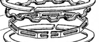
The possibility of axial displacements is eliminated by fixing the shaft using four thrust steel-aluminum half-rings, which are installed in the recesses of the engine crankcase and the main support cover. On the rear part (on the shank), the crankshaft is sealed with an oil seal pressed into the flywheel housing.
The role of connecting rod and main bearings is performed by the liner, which are installed in the so-called beds. Both main and connecting rod bearings are made of steel strip, which is coated with a layer of lead bronze. In the main bearings, the upper and lower parts are not interchangeable, since the upper parts have holes for supplying oil and grooves for distributing it. But the halves of the connecting rod bearings are interchangeable.
During engine operation, the KamAZ crankshaft journals wear out, and it is allowed to be ground four times, and the liners are available in seven repair sizes.
But another feature of the KamAZ crankshaft is that the block and connecting rods can also be bored to size.
Repair dimensions of crankshaft journals and bearing beds
| Connecting rod bearing | Main bearing | ||||
| diameter, mm | liner marking | diameter, mm | upper (lower) liner marking | ||
| crankshaft journals | connecting rod bed | crankshaft journals | bed block | ||
| 79,50-0,013 | 85,0+0,01 | 740.1004058 P1 79.50—85.0 | 94,5-0,015 | 100,0+0,021 | 740.1005170 (740.1005171) Р1 94.50—100.0 |
| 79.00-0,013 | 85,0-0,01 | 740.1004058 Р2 79.00 | 94,0-0,015 | 100,0 -0,21 | 740.1005170 (740.1005171) Р2 94.00—100.0 |
| 80,00-0,013 | 85,5+0,01 | 740.1004058 RZ 80.00—85.00 | 95.O-0.015 | 100,5+0,021 | 740.1005170 (740.1005171) RZ 95.00—100.5 |
| 79,50-0,013 | 85,5+0,01 | 740.1004058 P4 79.50—85.5 | 94,50-0,015 | 100,5+0,021 | 740.1005170 (740.1005171) Р4 94.50—100.5 |
| 79,00-0,013 | 85,5+0,01 | 740.1004058 P5 79.00—85.0 | 94,0-0,015 | 100,5+0,021 | 740.1005170 (740.1005171) P5 94.00—100.5 |
| 78.5О-0.013 | 85,0+0,01 | 740.1004058 P6 78.50—85.00 | 93,50-0,015 | 100,0+0,021 | 740.1005170 (740.1005171) Р6 93.50—100.0 |
| 78,00-0,013 | 85,0+0,01 | 740.1004058 P7 78.00—85.0 | 93.O-0.015 | 100,0+0,021 | 740.1005170 (740.1005171) Р7 93.00—100.0 |
Marks of the repair size and diameters of the crankshaft journals and beds in the block or connecting rod are applied to the back side of the liner not far from the parting plane.
The flywheel (Fig. 2) is necessary to accumulate kinetic energy during the power stroke and rotation of the crankshaft during auxiliary strokes, as well as to remove the piston from dead points and reduce the unevenness of shaft rotation.
The flywheel is cast from special gray cast iron. It is secured to the rear end of the crankshaft with eight bolts 3 made of alloy steel. Precise fixation of the flywheel on the crankshaft is achieved using two locating pins pressed into the end of the crankshaft. A ring gear 1 is pressed onto the machined cylindrical surface of the flywheel, intended for connection with the starter shaft gear when starting the engine. The clutch is installed at the rear end of the flywheel. To regulate the engine, there is a groove on the flywheel for flywheel lock 2 and 12 holes for turning the crankshaft with a crowbar.
Measuring related parts
Another way to determine the repair size involves sequential measurements of mating parts. The diameter of the bed is measured with a bore gauge. Then, using a micrometer and a bearing ball, the thickness of the liner is determined. Liner thickness measurements are taken closer to the middle. deviations in the shape of the bed should be taken into account and the gap should never be less than 0.03 mm.
It should be noted that when measuring bearing beds, it often turns out that their size exceeds the maximum size already specified in the literature by 0.02 mm. For connecting rods, this can be corrected by machining the bed hole, while machining the main bearing beds without specialized equipment is problematic. Their slight deformation can be compensated for by a corresponding slight increase in the shaft diameter. In any case, all dimensional changes should only be carried out after careful measurements to avoid errors leading to unacceptable reductions in bearing clearances.
For heavily worn shafts (journal wear is more than 0.10-0.15 mm), the determination of a repair reduction in the diameter of the journals has its own peculiarities. If the shaft is not deformed or has been straightened, then the main attention should be paid to the connecting rod journals. Thus, the maximum possible repair diameter depends on the wear and ovality of the journal. Practice shows that heavily worn journals are always oval, with maximum wear observed in the direction close to the radius of the crank. For example, the maximum wear of the journal is 0.15 mm, and the ovality is 0.1 mm, then the shaft journal will undergo a repair reduction of 025 mm. The runout of the main journals of the shaft further complicates the selection of repair sizes for the connecting rod journals, based on the condition of maintaining the piston stroke. In addition, after long-term operation of the engine and, especially, serious damage to the crankpins, the shaft may have residual twisting when, for example, the axes of paired crankpins do not coincide. The greater the wear and ellipse of the connecting rod journals and the smaller the grinding allowance, the more difficult it is, obviously, to ensure equality of the crank radii and the common axis of the paired journals. In practice, these requirements can often be met only with unreasonably large repair diameter reductions, and in some cases they cannot be met at all.
With severe wear of the connecting rod journal and minimal allowance for grinding, it is often necessary to switch to a new axis of the journal, shifted relative to the old one by a smaller radius by an amount close to half an ellipse.
Usually this value does not exceed 0.1-0.3 mm, which is acceptable for all types of passenger car engines (including diesel ones). An offset of more than 0.3-0.5 mm may be undesirable for diesel engines; it causes a noticeable reduction in the compression ratio. Therefore, in all cases where it is impossible to ensure identical crank radii, one should strive for their minimum difference.
Due to the deformation of the shaft, the axes of the connecting rod journals are shifted to different distances from the axis of rotation of the shaft. As a result of shaft deformation, the axes of the outer connecting rod journals slightly deviate from their previous radii, while the axes of the middle journals move to new radii of rotation (Figure 3.3.19 ), if these journals are in the plane of deformation of the shaft or near it (±30- 40°). The connecting rod journals, located in planes perpendicular to the plane of deformation of the shaft, are displaced in the circumferential direction.
Figure 3.3.19 — Transition of connecting rod journals to new radii of rotation when the shaft is deformed:
a - deformed shaft; b - the neck has a radius of rotation greater than the nominal one.
In practice, the most common case is when the shaft is maximally deformed along the most worn journal, and the direction of runout of the main journals is towards the connecting rod journal (compression of the shaft cheeks). Then mutual partial compensation of wear and runout occurs, as a result of which the repair diameter can be made slightly larger.
An elementary calculation shows that even if the connecting rod journal is not very damaged due to destruction of the connecting rod bearing, using a repair reduction of -0.25 mm turns out to be problematic. However, when assessing a repair reduction in journal diameters, it is necessary to focus primarily on minimal metal removal, and the conditions for equality of crank radii or the common axis of pairwise journals are secondary, but very desirable, especially from the point of view of shaft balance.
If a deformed shaft is not straightened, the following picture is often observed. After the destruction of the outer connecting rod bearing, a deformation of the shaft is formed at this journal in the plane of the shaft. Since journal wear is one-sided (from the top), it is partially compensated by runout. At the same time, the runout of the middle journals may turn out to be such that they will determine the repair reduction in size. The shafts of six and eight-cylinder engines exhibit a more complex picture, since their crankpins do not lie in the same plane. Thus, repairing deformed shafts without straightening is a rather complex technical task.
Depending on the deformation (runout) of the shaft, the repair methods will be as follows:
1) runout up to 0.08-^0.10 mm - traditional repair - grinding all journals to a repair size of 0.25 or 0.50 mm, it is possible to correct the front center chamfer; runout 0.10-0.20 mm - grinding to a repair size of 0.25+0.50 mm, welding (surfacing) of the shank and grinding from a new base is possible, the need for grinding the end surfaces of the shaft, balancing is possible;
2) runout of 0.20-0.40 mm or more, similar, but the repair size of the shaft journals is 0.50 mm or more, welding (surfacing) of the main journals with a runout of more than 0.40 mm is possible, welding of the shank and grinding of the end surfaces are required , balancing.
Many engines use flanged main bearings on crankshafts, made in one piece with thrust half-rings. For repairs, such liners are often supplied with an increased distance between the ends (for some engines there are options with both increased and standard widths), which involves grinding the end surfaces of the corresponding main shaft journal. Typically, the increase in size between the ends is two times less than the decrease in diameter, for example, for 0.25 mm liners, the end size increases by 0.10-0.15 mm, and for 0.5 mm - by 0.20-0.25 mm.
The essence of the problem with ring sizes on Aliexpress
VAZ 2109 hood size
Considering that Aliexpress is an international platform and sells its goods in the Russian Federation, the USA, and Europe, the sizing charts of goods must comply with regional standards. The question arises - what ring size is indicated in the lot, in what international standard? And how can we convert this size into one that is familiar to us, buyers from Russia?
An additional complication stems from the traditional Chinese laissez-faire attitude toward the characteristics of their products. Especially if the product is not expensive, such as rings not made of precious metals. How to find out the exact ring size, not plus or minus a centimeter?
What are the sizes of rings in general (and what is the difference)
In Russia, the indicated ring size is its internal diameter in millimeters.
In Europe there are several internal standards, but now in most stores you can find out the size as the length of the inner circumference in the same millimeters. Accordingly, the European size is easily recognizable in the lot on Aliexpress. European size starts with numbers around 40 mm, and Russian ring sizes are numbers from 14 to 22. And it is easy to recalculate, ring circumference (European size) = 3.14*ring diameter (Russian size).
The situation is worse with English, American and Japanese ring sizes. The British generally use the letters of their alphabet to designate ring sizes. As a result, there is not enough mathematics to translate these dimensions. Ring size tables are used to determine compliance. They are not difficult to find on the Internet and we won’t bother you with it here. Let us present only one short table.
How to correctly determine ring sizes on Aliexpress.
Is it possible to find out the vehicle's equipment by looking at the fault code? How to find out the car's equipment
Ring sizes on Aliexpress for all sellers without exception are expressed in the American measurement system.
In order to choose the right ring size for yourself, you need to look at the ring size correspondence table offered by the seller in the product card. If you know your standard Russian ring size, then a simple and clear size table will tell you whether it corresponds to the American size. To do this, just select the Russian size, which is equal to the circumference of the finger in mm.
Otherwise, buyer will have to measure the finger circumference by themselves as shown in the pictures. The images may differ from one seller to another, but the procedure itself remains the same. You need to take a piece of thread or a narrow strip of paper and wrap it around your finger. Next, you should mark the circumference of your finger with a marker and lay a thread or paper with a mark to the ruler. Substitute the resulting number in mm into the table and determine the correct ring size.
What should you pay attention to when independently measuring your finger circumference? On the shape of your own fingers and the quite logical difference in the methods of measuring ring size in different Aliexpress stores. One Chinese store may offer to measure the circumference of the finger joint, another - the circumference of the phalanx under the finger
It’s better to take measurements of both, and then choose the greatest result. Otherwise, the purchased ring will either not fit on your finger, or it will be very difficult to remove.
By the way, the table of ring sizing charts from different sellers is slightly different. There's nothing to be done, China is China. Therefore, in order to determine your ring size, you can either choose the average value of ring size indicators, or use the grid offered by a specific seller.
Buying different types of rings requires an individual approach. It's good if your choice is a ring with a changeable size. Then you won’t have to fool yourself with determining the correct size, but simply bend the rim of the ring a little.
And when buying a Chinese copy of a very original Cartier Trinity triple engagement ring, you will have to choose one size larger than yours. This is required by the design features of the ring - three thin bands of yellow, white and pink colors are connected to each other in a special way. Each ring individually may fit you perfectly, but the rings that fit into each other will be too small for you because of this connection. In order to freely put on and take off such a ring without feeling discomfort, an additional size is required.
Before you finally decide on the size and choose a ring, you should also read customer reviews and, just in case, consult with the seller about the correspondence of the size chart to the actual dimensions of the product.
https://youtube.com/watch?v=PYg0aKo4k8k
Assembly of the crankshaft with bearings after repair
The shaft journal-bearing assembly is assembled on the principle of complete interchangeability.
To ensure complete interchangeability of parts of an assembly unit, during manufacture or restoration it is necessary to process both the crankshaft journal and the bearing with certain accuracy standards that determine the tolerance range of the parts.
If, when processing a batch of parts with a tool configured for size, deviations from size are formed under the influence of a large number of independent or weakly dependent random factors, then their distribution curve corresponds to the normal law or the Gaussian curve. For the normal distribution law, from the conditions of complete interchangeability, the tolerance is taken equal to ±3 σ
, i.e.
6 σ
(
σ
– standard deviation).
Table 5.1
Initial data for assembly calculations
crankshaft with bearings
| Diesel brand | Repair shaft diameter dр, mm | Maximum deviations of the shaft journal size, mm | Maximum error deviations K | Installation gap value, mm | Limit deviations of bearing diameter, mm | ||
| Smax | Smin | ES(Dp) | EI(Dp) | ||||
| Upper es(dp) | Lower ei(dp) | ||||||
| 6ChSP18/22 | Indigenous 134,536 | -0,025 | ±2,5 | 0,16 | 0,12 | +0,2 | +0,1 |
Let us determine the number of crankshaft journals in a batch of 200 pieces, the deviations of which are within ±2.5 σ
:
From Table 6.1 we find that Ф
(2.5) = 0.09275, and since the Gaussian curve is symmetrical with respect to the arithmetic mean size, then 2
Ф
(2.5) = 0.1855. It follows that 86.64% of the necks have specified deviation limits.
Their number will be equal to:
Tolerance for neck processing:
Since the curve is symmetrical, the arithmetic mean is:
Deviation values for the diameter of parts are within ±1.5 σ
:
Thus, 37 parts from a batch of 200 pieces will have dimensions within
with a tolerance of 0.02 mm.
Maximum deviations of the bearing diameter, ensuring the assembly of the unit according to the principle of complete interchangeability:
EI
and
ei
– lower limit deviations of the bearing and shaft journal, mm;
ES
and
es
– upper limit deviations of the bearing and shaft journal, mm;
Smax ( M ) _
and
S min ( M )
– maximum and minimum values of the installation gap, mm;
Arithmetic mean diameter:
Standard deviation:
Distribution coefficient:
Integral value:
From Table 6.1 we find that Ф(К 1 )
=0.2257, and
Ф(К 2 )
=0.4641.
Subtraction gives the relative number of parts in a batch with deviations from K1 to K2.
Number of bearings that provide the required assembly conditions with the shaft journals:
.
How the crankshaft is bored
Let's start with the fact that boring and grinding a crankshaft with your own hands in a garage can only be done by experienced specialists who have the appropriate set of special equipment. First of all, a crankshaft boring machine must be available, since the entire procedure must be carried out with high precision. It is also necessary to take into account that the complexity of further adjustment of the repair liners will directly depend on the quality of work on the crankshaft.
Also, some car enthusiasts, in order to maximize savings, manage to grind the crankshaft in the garage with improvised means, but this procedure is strongly not recommended, since the result can be completely unpredictable.
Let us add that before starting work, a specialist must check the crankshaft for axial displacement of the connecting rod journals, bending of the crankshaft, etc. At the same time, it still turns out that although shaft repair is a complex turning operation, buying a new part will still be on average 50-60% more expensive compared to how much it costs to bore a crankshaft by an experienced craftsman.
Characteristics of crankshafts
Characteristics of crankshafts photo, Instructions for engine modification, engine tuning
Of course, it is difficult to single out any of the most important parts in a car, but the crankshaft can be considered one of the most important, because it is the one that converts the forces from the pistons and connecting rods into torque, which moves the car.
In this article we will look at some parameters of crankshafts for “classics” and the features of their replacement and installation.
So, “classic” crankshafts have several parameters that may differ.
1. Crankshaft stroke - the distance between the axes of the connecting rod journal at bottom dead center (BDC) and top dead center (TDC)
On classic engines, the factory installed crankshafts with a stroke of 66 mm, 80 mm and 84 mm. In addition to them, there are sports crankshafts with a piston stroke of 86 mm, 88 mm and even 90 mm. However, you should not think that by installing a crankshaft with a stroke of 90 mm in the block, the engine will immediately become much more powerful. The behavior of the engine is greatly influenced by the ratio of the length of the connecting rod and the stroke of the crankshaft - the so-called R/S. Many believe that the “golden mean” of a cylinder block is an R/S value of 1.75.
If R/S is large, then the piston remains at TDC longer, therefore more complete combustion of the fuel mixture occurs, hence greater pressure on the piston after passing TDC. The result is good torque at medium and high speeds. Also, a long connecting rod reduces its friction against the crankshaft. However, there are also disadvantages - with a long connecting rod and a short stroke, due to a decrease in air flow speed (again due to the lower piston speed after TDC), good filling of the cylinders at low and medium crankshaft speeds is not ensured. There is also a high probability of detonation due to the high temperature in the combustion chamber and the long time the piston remains at TDC.
If R/S is small, then a very good cylinder filling rate is ensured at low and medium crankshaft speeds, and also due to the short time spent at TDC (and therefore the higher piston speed at the beginning of the stroke), the mixture becomes more homogeneous, which contributes to better combustion. But there are also disadvantages here - a small R/S value means a larger angle of inclination of the connecting rod. Therefore, a large force will push the piston in a horizontal plane. Therefore, the load on the connecting rod, on the walls of the cylinder block, and the pistons of the ring increases, the operating temperature increases due to increased friction, and lubrication deteriorates. Well, due to the increased piston speed, the engine life is also reduced.
Another common problem when installing a crankshaft with a long stroke is the connecting rod touching the block wall. In this case, you need to refine the wall using a grinder or grinder.
2. Crankpin size
The crankshaft journal is a support with which the shaft is connected to the connecting rods.
The standard diameter of the connecting rod journal in a “classic” engine is 47.8 mm. The rolling bearings and connecting rods are also made to this size, however, on “sports” crankshafts with a stroke of 86 mm, 88 mm and 90 mm, the diameter of the connecting rod journal can be 43 mm. It requires special liners, as well as connecting rods, don’t forget about it!
3. Number of counterweights
Counterweights provide unloading of the main bearings from the centrifugal forces of inertia of the unbalanced masses of the crank and the lower part of the connecting rod. On standard crankshafts 2101 2103 there are only 4 counterweights, essentially on one side on the cheek (the main and connecting rod journals are connected) from the main support. On the remaining crankshafts 21213 and with a stroke of 86 mm, 88 mm, 90 mm there are already 8 of them, which ensures a more balanced unloading of the main bearings from inertial forces.
Crankshaft 2103 with four counterweights
Crankshaft 21213 with eight counterweights
| Sports camshafts Sports camshafts |
| Multi-throttle intake Multi-throttle power system |
| Direct exhaust systems Direct exhaust systems |
Spider 4-2-1 or 4-1 Spider choice 4-2-1 or 4-1 |
Characteristics of camshafts Characteristics of camshafts |
| Characteristics of crankshafts Characteristics of crankshafts |
| Methods for modifying the cylinder block Modification of the engine cylinder block |
Lightweight crankshaft Lightweight crankshaft |
| Forged pistons Advantages of forged pistons |
| Split camshaft gear Split camshaft gear |
| Sports receiver Sports receiver |
| Comparison of fuel pumps Which fuel pump to choose |
| Zero resistance air filters Zero resistance air filters |
Engine malfunction
Naturally, the connecting rod and crankshaft became unusable. The photograph clearly shows longitudinal cracks on the connecting rod journal of the crankshaft.
Upon closer examination, the main reason why the engine failed was discovered. On the connecting rod of the third cylinder there was a connecting rod cap of the second cylinder, and on the connecting rod of the second cylinder there was a connecting rod cap of the third. Again, strangely, the crankshaft should jam immediately when tightening, but apparently the covers matched each other.
And so I had to change two connecting rods and the crankshaft. They did not disassemble the cylinder head. The valves on the head were in good condition at the last overhaul, ground in, and the oil seals were also replaced. This engine has a weakness; the studs, with the help of which the camshafts are attracted in bed, are easily pulled out of the threads. Which leads to additional costs.
Installing the crankshaft
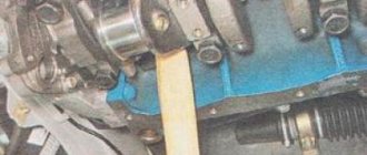
After the parts were washed from dirt and used oil, assembly began. First of all, we install the crankshaft, having previously installed the main bearings.
After installation, the bearings must be lubricated with engine oil. Which you will use in the future. Don't forget, the earbuds have locks. They are inserted into specially provided grooves in the block bed. In addition, there is a peculiarity of modern earbuds: they come in different sets. Half of them have a lobe groove. To supply oil to the crankshaft journals. We install them in the engine block. Inserts that do not have grooves are installed in the main covers. Before installing the covers, it is necessary to install axial displacement half-rings. There are grooves for them in the engine block on the bed of the third main journal. We install the half rings in such a way that the side intended for sliding is directed towards the crankshaft. This side has a characteristic coating and channels for lubricant.
Then we tighten the covers with bolts. Here, under no circumstances should the covers be mixed up, and also the liners installed in the block and the main covers must be positioned lock to lock. This is very important, as a mistake will lead to immediate, costly failure or the shaft will simply jam when tightened. Repairing a VAZ 2112 engine is not very difficult, but simple mistakes due to inattention lead to disastrous results, as in our case.
All covers must be tightened evenly, in several stages; it is very important that the loads on the main journals of the crankshaft during tightening are distributed evenly, because this will prevent damage to the shaft itself and the liners. The final tightening of the covers must be done using a torque wrench with a force of 66.31-84.38 N*m .
After tightening, we turn the crankshaft; it should rotate freely by hand, turn it several times, the resistance exerted by the shaft during rotation should be uniform without biting or braking, if this is not the case, then you need to look for the problem.