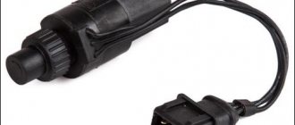
The speed sensor (DSS) is designed to record the speed of the vehicle and transmit this information to the ECM. When the car moves, for every meter of movement the DSA generates six pulses. Based on the pulse repetition rate, the controller determines the speed of movement.
Location of the speed sensor on Kalina and Priora
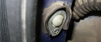
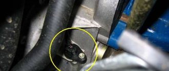
The speed sensor is installed on the gearbox housing, to the left of the dipstick. It is fixed with a bolt at “10”, and in order to get to it, it is better to remove the battery (although it can be removed without removing the battery).
Location of DSA Priora
Speed sensor Priora, Kalina
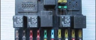
VAZ speed sensor pinout and DS connection diagram
The speed sensor is an element of the vehicle's electronic control system. It depends on its readings how much fuel will be supplied, how much air will bypass the throttle valve when idling, and what the speedometer readings will be.
The speed sensor of a VAZ car is based on the use of the Hall effect, that is, a stream of pulses is transmitted from the device to the car's ECU, the frequency of which is proportional to the speed of the car. Auto electronics, analyzing incoming data, selects the required idle speed and sends a signal to a device that regulates the engine idle speed, which optimizes the composition of the air-droplet mixture entering the combustion chamber, bypassing the throttle valve.
During a distance of one kilometer, the speed sensor transmits over 6000 pulses to the ECU. Based on the parameters of the time analysis of inter-pulse signals, the on-board computer transmits data to the dashboard, thereby determining the speedometer readings.
As in many other cars, the VAZ speed sensor is located in the upper part of the gearbox housing, not far from the engine oil level dipstick. You can get to it from two sides: from above, by opening the hood and disconnecting the adsorber, and from below, using the inspection hole for convenience.
Functionality, types, design and principle of operation of speed sensors
Speed sensors, regardless of type and design, generate signals that can be sent either directly to the speedometer or to the engine controller and associated electronic control units.
In the first case, the sensor is used only to visually determine the speed of the vehicle. In the second case, the data is used by automotive electronics to control the engine and other systems, and the signal to the speedometer is supplied from the controller. On modern vehicles, the second connection method is increasingly used. Measuring speed using DSA is quite simple. The sensor generates a pulse signal (usually rectangular), in which the pulse repetition rate depends on the speed of rotation of the shaft and, accordingly, on the speed of the vehicle. Most modern sensors produce from 2000 to 25,000 pulses per kilometer, but the most commonly used standard is 6000 pulses per kilometer (for contact sensors - 6 pulses per revolution of its rotor). Thus, measuring speed comes down to the controller counting the repetition rate of pulses received from the DSA per unit time, and converting this value into understandable km/h.
Speed sensors are divided into two large groups:
- Directly driven from the shaft, or contact;
- Contactless.
The first group includes sensors to which torque from the gearbox shaft, axle or transfer case is transmitted through a drive gear and a flexible steel cable (or a short rigid shaft). The sensor contains a device that reads the angular rotation of the shaft and converts it into electrical impulses. Sensors of this type are widely used, since they can be installed instead of a mechanical speedometer drive (which makes it possible to modernize old vehicles without extra costs) and are highly reliable.
The second group includes sensors that do not have direct contact with the rotating shaft. To measure speed with such sensors, an auxiliary device is installed on the shaft - a drive disk or rotor. Contactless devices are becoming increasingly popular; they are also installed on many current models of domestic cars.
All sensors operate on different physical principles. Contact devices most often use the Hall effect and magnetoresistive effect (MRE), as well as optocouplers (optoelectronic pairs). At the heart of non-contact sensors, the Hall effect is most widely used, and MRE is much less commonly used. The design and operating principle of each type of sensor is described below.
Pinout DS 2109, 2110, 2112, 2114, 2115
If you understand how to connect the speed sensor, then there is the following pinout that you should follow. At the same time, it is important to understand the essence of the operation of the DS to study the circuit diagram of the sensor, which is attached to this article.
The factory speed sensor of VAZ cars is manufactured with some differences in connections to the block connector. The square-shaped connector is used in Bosh electronics systems. The circle-shaped connector is used in electronic systems such as January 4 and GM.
When connecting a sensor, you should choose devices with contact group digitization such as “-”, “A”, “+” (internal designation on the block contacts) instead of digital designations such as “1”, “2”, “3”. In addition, preference should be given to devices with a metal-type rod, since plastic rods are very short-lived.
Diagnostic connector type Priora
During the development of “injection” cars, various options for interrogating the ECU (electronic control unit) were developed. At first it was a system for reading codes using a warning lamp. Under special conditions different for different injection systems, the warning lamp began to flash. The master could only write down the rhythm on paper and, checking the table, determine the error.
Subsequently, special diagnostic devices were developed:
- Diagnostic adapters for personal computers.
- Automotive diagnostic scanners.
There are separate articles describing the operation of these devices. But they undoubtedly have one thing in common: a special connector is needed to connect the equipment with the ECU. At first these plugs were made different for each brand of car. There were both round and square. And just paired holes for the dipstick, like on VAG systems. But gradually manufacturers began to think about unification. So, by the early 2000s, the OBD-2 diagnostic connector, now so widespread, appeared.
OBD-2 connector design and its contacts
This connecting plug is made of plastic. The connecting part looks like a trapezoid (see photo). In total, it has 16 female contacts. The countdown starts from the top row, from left to right. The top row is considered to be the wide side of the trapezoid. The following sockets are used for the Priora car:
- Ground (ground), slots 4 and 5.
- Constant “+” 12 Volts - 16.
- Diagnostic socket - 7.
Typically, the equipment is connected to this connector through a special “plug”. The connector plug is of the same shape, but of the male type. Although those who work with various adapters can make connections directly. This is done on some types of adapters that have a separate probe for the K-line. You just need to remember that the “+” and “-” for the equipment must be taken from the battery of the vehicle being tested. Otherwise the communication signal will be incorrect.
Diagnostic connector location
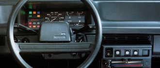
In addition to the fact that these connectors had different shapes, they were located in different places. On the Priora, it is hidden very cleverly. Without knowing where exactly it is located, finding it is very problematic.
Don't let the fog in. The OBD-2 diagnostic connector on the Priora is located on the inner wall of the glove box on the passenger side. As they call it - the glove compartment. On the part that is adjacent to the “beard”. This is clearly visible in the photo. An experienced specialist, a master diagnostician, will connect with a standard connector by touch without any problems. Simply by opening the box and feeling for the nest behind its wall.
For novice diagnostic specialists, it is better to act according to the instructions. In order. That is, open the glove box completely. It will hang on the side plastic guides. Press these thrust plates a little, and the glove compartment will fold back further.
Carefully pull out the side tabs and release the glove box completely. Then access to the diagnostic input plug will be completely free.
Well, then proceed according to the instructions for connecting the available equipment.
Useful video about the location of the diagnostic connector on the Priora:
How to check the VAZ speed sensor
A failed speedometer sensor in a VAZ car is easily determined - in this case, the speedometer stops working, and it may also show some signs of life, but display incorrect information.
Using a tube, pliers or other available tools, rotate the sensor axis. In this case, you should see the voltmeter readings changing: the higher the speed, the higher the voltage (from 0.5 to 10 V). If this does not happen, the sensor requires replacement.
Replacing a car speed sensor
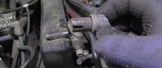
As for its location, look for the DS in the engine compartment in close proximity to the exhaust manifold. To be honest, the place where it is installed cannot be called ideal. While the car is running, the manifold heats up. The sensor wires rub against it, which over time leads to malfunctions and short circuits. Therefore, experts recommend that the first step is to properly insulate the wiring, and also use some kind of clamps so that the wires do not come into contact with the collector. This significantly extends its service life.
If the check shows that the DS is faulty, it needs to be replaced. Repairing sensors and similar small electronic devices is a thankless task. In a garage environment, this is unlikely to be possible, and the only thing that can be done is to clean the contacts from oxidation (this can be a problem).
It doesn’t matter whether you have an injection car or a carburetor with a Europanel - the connection of the speed sensor to the instrument cluster is identical.
Replacing the VAZ speed sensor: step-by-step instructions:
- Drive into the pit - it will be more convenient to work from below - and wait until the engine cools down.
- Turn off the vehicle's power by removing the cable from the negative terminal of the battery. Do not close the hood after this, this will provide you with lighting.
- Locate the speed sensor on the transmission. Clean it and everything near it with a rag to remove any dirt.
- By pressing the spring clip, disconnect the wire block from the sensor.
- Dismantle the sensor itself by unscrewing it counterclockwise - with your fingers or an open-end wrench to “22”.
- Carefully, so as not to break anything, install a new part in place of the removed part. Connect the wire block to it and the procedure for replacing the speed sensor can be considered complete.
How to properly connect a new DS? It is important here that the device rod fits correctly into the fixing sleeve, otherwise rotation will not be transmitted to the sensor. If the sensor fits into the socket the first time, then everything is in its place, and if something prevents it from moving, then the rod did not fit into the bushing.
The result of the work
Now you need to check the operation of the sensor in motion. Start the engine and drive around. Pay attention to the speedometer and odometer readings. Test the car for acceleration by pressing the accelerator pedal hard. If everything works normally, the problem has been successfully resolved.
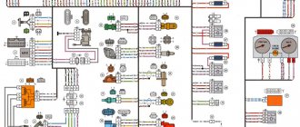
General diagram of the electrical equipment of the VAZ 2170 Priora (sedan)
1. List of elements of the electrical connection diagram of the instrument panel harness of the LADA 2170 car: 1, 2, 3 blocks of the instrument panel harness to the front harness; 4 instrument panel harness connector to rear harness; 5 contacts of the mounting block; 6 brake light switch; 7 instrument cluster; 8 lighting control module; 9 driver airbag module; 10 horn switch; 11 diagnostic block; 12 on-board computer mode switch; 13 ignition switch; 14, 15 blocks to the electric power steering control unit; 16 electrical package controller; 17 light signaling switch; 18 windshield wiper switch; 19 gear motor for air flow distribution; 20 heater control unit; 21 heater motor switches; 22 rear window heating switch; 23 hours; 24, 25 connectors for the instrument panel harness to the radio; 26 hazard switch; 27 glove box lighting; 28 glove box lighting switch; 29 instrument panel harness connector to the ignition system harness; 30 control unit for the airbag system. * A1, A2, A3 grounding points of the instrument panel harness. B block of the mounting block. The wires in this diagram have a letter designation of color and a designation of the number of the circuit element to which this wire is connected. The number of the block contact is indicated through the fraction. Instrument panel harness 2170 3724030.
Priora speed sensor 16 valves pinout
- To the beginning of the forum
- Forum Rules
- Old design
- FAQ
- Search
- Users
1 brown, 2 gray, 3 pink with black stripe
I don’t have a Priora, but in all schemes, including e-gas, it’s the other way around: 1 - pink (+12V) 2 - gray (signal) 3 - brown (ground)
Change pink with brown, you have confused the sensor's power supply with ground. How can you randomly connect wires in the engine control system on a new car? Do you want to kill the ECU?
IMHO Genady you are wrong, but thanks for your participation. Today I reviewed the diagram again, I assembled everything correctly. Why didn't it work? I guess I just didn't tighten something up. I would also like to note that mainly sensors 2170-3843010-04 are available for sale. I have 2170-3843010-02 and it turned out to be very difficult to find one in the rather large Chelyabinsk. which 04 stupidly does not reach the end 3-4mm, it is a little thicker and has a slightly different shape. It’s hard to say why they did such crap at VAZ, but I didn’t think that I would experience problems with the spare part with the Priora.
Why is the old guy fucked up, he ordered me to live long.
No, it works, but every trip it cuts out for 5-10 minutes, this is very annoying, because... The EUR is cut off, the engine becomes very jerky without any speed readings, you drive in some jerks. Apparently water gets into the sensor through the gap and the board in it oxidizes. On the new one, I covered this gap with super glue. This is the kind of laboratory work I did, although I could have just rolled it out under warranty
Source
Checking the induction DS
The signal that comes from the rotation of the wheels essentially resembles the oscillation of a wave impulse. Therefore, the voltage changes depending on the rotation speed. Everything happens in the same way as with the crankshaft angle sensor.
Subscribe
to our channel in
Index.Zen
Even more useful tips in a convenient format
If the sensor is working properly and the gear is not leaking, then there may be no power to the sensor or there is a break/short somewhere in its wiring. In addition, the ECU and ABS are involved in the readings on the tidy. The wire from the ECU to the instrument panel or from the ABS may have been lost (you should call the wire from the speedometer to the ABS block). It is possible that the device is faulty.
Good day everyone, I have such a problem that the speedometer and odometer do not work. My car is a Hyundai Santa Fe 2 2007. I checked the speed sensor drive gear, everything is ok, I don’t know how to ring or check the sensor itself. The workers checked the inductive sensors on the box by eliminating everything, the check light came on, I don’t know what else could be the reason, since you drive with a scanner, the speed shows “0” on the speedometer, maybe someone has someone who can tell me.
Guys, good afternoon everyone! Please tell me! I have a Lada 14 and just recently the speed began to fluctuate, it almost stalls, it does not work evenly. Diagnostics showed a camshaft sensor, they replaced the sensor with a new one, but there was no result. By the way, the speedometer and tachometer do not work. What could be the reason?
Thank you, detailed article!
And it will be even more clear how to check the speed sensor if you watch the video of the HF channel: https://youtu.be/qiDmZLUuTMI
Priora speed sensor pinout
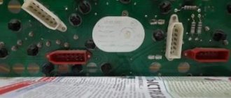
The difficulty was that it was not possible to remove the contacts from the chip right away (I couldn’t find any information on such a petty procedure on the Internet, there was one post where a man couldn’t remove it and sawed it off! The connector) he tore off one wire and, without torturing the remaining ones, cut off the entire connector. In general, the essence of the message, the internal appearance of the connector is misleading and at first glance it seems that the antenna that holds the contact alone is a lie! there are two of them!
To remove the contacts you will need an awl, in my case half a honey. tweezers, another difficulty is that the mustache is springy, that is, we pull the wire and press the mustache, but pull it moderately so as not to press the mustache into the plastic of the connector. Regarding the silicone inserts, they create resistance, but the moment when the contact is released is basically noticeable. If you are reading this article after you have already torn off the wire)), then it will be easier to remove it by pressing with a small flat screwdriver across the contact plates, in this case there will be room for the awl to press the mustache, but you will have to suffer.
Now recovery. The contact for restoration is very inconvenient; in the place where the wire is crimped, it has greater strength, so I don’t recommend trying to open it and insert a new wire. The maximum that I could do, without causing much damage, to remove the remnants of the wire, was to open the crimping area with a small clock screwdriver, hitting it with a hammer, but the contact must be placed on a convex surface.
Connected by soldering. If you follow my path, then get ready for inconvenience; soldering contacts to wires will be inconvenient. We put silicone plugs on the wires, strip the wires to a length of 3-4 mm, tin (I use Zil-2 flux, a 100 W soldering iron) and move the plug to the edge of the wire so that about 1 mm of its insulation is visible. We insert the wire into the contact using rotational movements. Having aligned it at the junction, apply acid. We solder carefully so that the tin does not flow into the contact and solder its insides; it will be almost impossible to remove the tin and the functionality of the contact will be lost. In the photo: the top contact is soldered, the middle contact is prepared for soldering, the bottom wire is tinned.
That's it, after soldering we go through with a dry brush to remove any remaining acid (not necessary, since during soldering it all basically boils away), spread the mustache a little, remove dirt from the connector and insert the contacts into place, pushing the contacts from the side of the silicone plug, resting against it with a screwdriver until you hear a characteristic click.
Pinout DS 2109, 2110, 2112, 2114, 2115
If you understand how to connect the speed sensor, then there is the following pinout that you should follow. At the same time, it is important to understand the essence of the operation of the DS to study the circuit diagram of the sensor, which is attached to this article.
The factory speed sensor of VAZ cars is manufactured with some differences in connections to the block connector. The square-shaped connector is used in Bosh electronics systems. The circle-shaped connector is used in electronic systems such as January 4 and GM.
When connecting a sensor, you should choose devices with contact group digitization such as “-”, “A”, “+” (internal designation on the block contacts) instead of digital designations such as “1”, “2”, “3”. In addition, preference should be given to devices with a metal-type rod, since plastic rods are very short-lived.
Diagram and pinout of DS Priora
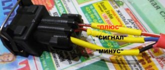
Three wires are connected to the DS Priora plug. One of them is positive 12V, the second or central one is the signal wire that supplies impulses to the control unit, and the third is ground.
The speed sensor power supply circuit is shown in the photo below.
The DS pinout diagram on a Priora may be needed when replacing a plug or checking the incoming power.
How to check the VAZ speed sensor
A failed speedometer sensor in a VAZ car is easily determined - in this case, the speedometer stops working, and it may also show some signs of life, but display incorrect information.
Using a tube, pliers or other available tools, rotate the sensor axis. In this case, you should see the voltmeter readings changing: the higher the speed, the higher the voltage (from 0.5 to 10 V). If this does not happen, the sensor requires replacement.
Symptoms of a faulty speed sensor
If your car has at least one of the following reasons during operation, this will be one hundred percent reason to check it.
- Unstable operation at idle.
- Fuel consumption has increased.
- The engine does not “pull” or is no longer as responsive as before.
- The speedometer does not work or there are errors in the operation.
- The electric power steering is turned off.
If an on-board computer is installed on the car, then errors coming from the speed sensor will also be a reason for checking.
Causes of malfunction
The most common cause of speed sensor failure is faulty wiring. It is highly exposed to external weather conditions, oxidizes and rusts. Thus, only an external examination will give the correct answer.
One of the sensor contacts has fallen off due to corrosion.
After the wiring and sensor are inspected, we proceed to dismantle it. How to properly carry out this operation is written in this article.
Basic faults
The most common symptoms of a speed sensor malfunction on Priors and Kalinas include:
- the dashboard displays fuel consumption significantly higher than the actual indicators;
- Unstable engine operation at idle speed;
- noticeable reduction in engine power;
- the mileage readings on the odometer do not change;
- the speedometer does not work - the needle is at zero, or jumps from 0 to 200 km/h, or from 30 to 200 km/h, despite the fact that the car is moving at a different speed;
- when the speedometer needle lies at 0 km/h for 5 minutes, the power steering switches off and after that the electric power steering fault lamp lights up on the panel.
Mostly the faults concern wires, the insulation of which can crack over time. Also, oxides and dirt may appear on the contacts; to remove them, you can use special contact cleaners.
The main causes of such problems are the contact of antifreeze/water/oil on the contacts, which then oxidize, as well as failure of the speed sensor. In severe frosts, antifreeze can drip onto the sensor from the pipes located above it, and water gets in when the car drives through puddles in wet weather, or in winter in the form of snow when driving through snowdrifts.
Also, the sensor may be heavily clogged with metal shavings, which appear due to the grinding of gearbox parts. The sensor itself may fail due to insufficient sealing of the housing. The fact is that these sensors can be of 2 types - collapsible and non-removable. In dismountable sensors, the 2 parts of the housing are fastened together with glue, and in non-dismountable sensors, the housing is filled with epoxy. If the seal is insufficient, water/antifreeze can get inside both options, as a result of which the 3 contacts soldered to the small board become oxidized. As a result, glitches appear from time to time, and then the speed sensor stops working altogether.
How to determine the cause of the problem
The most common malfunction is uneven speedometer readings while driving. Jumps and "falls". In this case, most likely, the DSA needs to be replaced.
If there is no signal from the speed sensor, there may be a problem with the wiring, ECM, or main relay.
Sensor check:
Checking the speed sensor on Kalina using a control
- turn off the ignition;
- disconnect the wire connectors from the speed sensor and from the controller;
- check the circuit between contact “X2/32” of the controller block and contact “2” of the DSA block;
- check the circuit - controller block contact “X2/47”, DSA block contact “3”;
- check the circuit between contact “1” of the DSA block and the main relay.
If the circuits are in good condition, then the DSA must be replaced.
Replacing a car speed sensor
As for its location, look for the DS in the engine compartment in close proximity to the exhaust manifold. To be honest, the place where it is installed cannot be called ideal. While the car is running, the manifold heats up. The sensor wires rub against it, which over time leads to malfunctions and short circuits. Therefore, experts recommend that the first step is to properly insulate the wiring, and also use some kind of clamps so that the wires do not come into contact with the collector. This significantly extends its service life.
If the check shows that the DS is faulty, it needs to be replaced. Repairing sensors and similar small electronic devices is a thankless task. In a garage environment, this is unlikely to be possible, and the only thing that can be done is to clean the contacts from oxidation (this can be a problem).
It doesn’t matter whether you have an injection car or a carburetor with a Europanel - the connection of the speed sensor to the instrument cluster is identical.
Reasons for failure of the speed sensor on a Priora
As mentioned above, on a Priora the speed sensor is a pain. Moreover, its malfunctions do not appear after 100 thousand kilometers, but literally from the first days of operation of the new car. The reason for this is various factors:
- Oxidation of contacts - this phenomenon occurs due to a violation of the seal of the plug.
- Liquids getting inside - and although the sensor’s power supply chip (plug) is sealed, the possibility of oil and other aggressive substances (antifreeze, water) getting inside the connection cannot be ruled out.
- Damage to contacts - oxidized contacts simply fall off over time, breaking the electrical connection. Moreover, this happens even if the chip was not disconnected from the sensor.
- Violation of the integrity of the plastic housing - if the sensor housing is damaged, the product will not function.
- Damage to power cords. On Prioras, this phenomenon is very common, and if you determine that the sensor is working, then you should check the quality of the wires in the area where they enter the chip.
- The presence of dirt on the sensor body, which is a common cause of interruptions in the speed indicator. Small metal particles act as contaminants (production of gearbox gears). The particles are magnetized to the DS body.
Although the speed sensor on the Priora is relatively inexpensive (500-800 rubles), you should not rush to buy a new element. After all, the reason can only be contamination of this device or damage to the supply wires. That is why you first need to identify the cause of the breakdown, and only after that resort to eliminating it.
Speed sensor Lada Kalina
I encountered the following problem - the speed sensor on Kalina quickly failed. More specifically, in about a year and a half I replaced 3 speed sensors. Moreover, the latter did not work even a day. This arrangement of events did not suit me and, to be honest, I was a little fed up. I decided to figure out the reason for such a quick “demise” of the sensors.
A speed sensor can break down mainly for 3 reasons - the first, and most common, is liquid (water or antifreeze) getting on the sensor contacts. This occurs due to leaking pipes or driving through a large puddle. The second reason is transmission oil getting inside the sensor. This is due to the design features of the sensor itself. And third, the speed sensor chip may begin to melt; no one knows for sure why this happens.
The first time my speed sensor failed was due to antifreeze getting on it. I fixed the leak (the pipes leading to the stove were leaking, just above the sensor) and replaced the sensor. The second time the speedometer stopped showing after a trip in rainy weather, although it didn’t seem to drive through puddles. The third time I didn’t understand at all why it stopped working, perhaps the microcircuit itself burned out, but this is no longer so important.
Replacing DSA
On cars with an 8-valve engine, it is most convenient to approach the speed sensor from the right side, while removing the corrugation that goes from the air filter to the damper. On cars with a 16-valve engine, it is more convenient to get to the sensor near the washer fluid reservoir, which, by the way, does not need to be dismantled.
The new DSA must fully match your model. Check that the part number matches (on the housing head)
Dismantling
With the ignition off, disconnect the wiring harness connector. Then, using a 10mm wrench, unscrew the fastening nut and remove the DSA from the socket.
Notes from practice.
To facilitate access to the sensor, loosen the clamp securing the air filter pipe and move the pipe to the side. Immediately after disconnecting the block with wires, secure or tie it down, otherwise it will fall. Often problems arise precisely when being removed from the nest. The magnet located inside the DSA, during operation, collects metal shavings on the body. The solution is, at the risk of damage, to pry it with something like a screwdriver (preferably two on opposite sides).
Installation
Installing a new speed sensor
- Before installation, lubricate the speed sensor housing at the location where the sealing ring is installed with grease such as graphite, grease, or ShRB. This will not damage the sealing ring (oil-resistant rubber) and will make removal easier in the future.
- We install the DSA in place.
- We screw in and tighten the fastening nut with a torque of 4.5...7.2 Nm. We connect the block of wires.
- Reinstall the air filter pipe.
Types of speed sensors, their differences. Where is the speed sensor located?
Electronic 6-pulse sensors are equipped with cars with injection engines, launched into series since 2006.
On carburetor Samaras you can sometimes find 10-pulse EMF.
- Until 2006, VAZ cars used mechanical devices in the form of special inserts between the speed indicator cables and the gearbox gear outputs.
The key difference between different types of EMF is the absence of wires and connecting connectors. For example, GM or Yantar systems are equipped with products with round (oval) ports. At the same time, Bosh uses wireless versions with square connectors.
- On the VAZ-2110 (2111, 2112), speed sensors are mounted on the gearbox housings slightly to the right along the route, directly next to the oil control dipstick.
- The device is easy to find by looking in the area of the right CV joint.
- On the VAZ-2115, the electronic device is mounted on top of the front part of the gearbox (along the way) directly above the differential. The product with the connected cable is secured with one bolt on the box body.
Speed sensor malfunctions
Typical symptoms of failure of the electronic speed sensor may be:
There can also be several reasons for problems with the Electronic Speed Sensor, for example:
- power supply circuit break,
- oxidation of contacts,
- breakage of connecting wires or wear of the mechanical drive of the sensor.
Description of DS
checking the oil pressure sensor viburnum
As we have already said, the main purpose of the speedometer drive sensor is to accurately determine the speed of the vehicle. Thanks to this device, the model can always know at what speed his car is moving. As for the varieties, DS can be of the contact or non-contact type. Today, most of our compatriots prefer contactless options. Contact DS, despite all the advantages, have one significant drawback - they are prone to contamination, which in turn will lead to inaccuracy of the displayed readings.
Design and principle of operation
Structurally, according to the diagram, this part consists of:
- speedometer drive;
- housings;
- as well as the controller itself with a connector for connecting to the on-board network.
As for the principle of operation, it is based on measuring the frequency level of signals from the controller, which is located on the gearbox housing or transfer case. At the output of the device, while driving, rectangular pulses are formed, the minimum value of which should be at least 1 volt, and the maximum value should be at least 5 volts.
According to international standards, the controller must generate about 6 thousand such pulses over one kilometer. The pulses themselves are subsequently converted into current, which is measured by a magnetoelectric device. It should be noted that the current value directly depends on the number of signals supplied per certain unit of time. That is, this value will be directly proportional to the speed of the vehicle.
In addition, thanks to the electronic circuit installed in the dashboard, the operation of the stepper motor is ensured by counting incoming signals. The latter is designed to rotate the counter reels, after which it displays the relevant information on a small screen, where the total and daily mileage of the car is shown. If we are talking about daily mileage, then this value can be reset to zero if necessary.
Symptoms of a problem
If the DS for some reason fails, this will lead to the control unit being unable to determine the speed of movement. However, this is not the only problem, since malfunctions in the performance of the power unit may also occur.
We suggest that you familiarize yourself in more detail with the signs of a malfunction, by which you can determine the failure of the DS:
- the speedometer on the dashboard has either stopped working altogether or displays incorrect readings;
- malfunctions appear in engine operation, in particular at idle speed;
- fuel consumption increased;
- engine performance has deteriorated, the power unit cannot reach the required speed;
- the engine may stop spontaneously while idling, in particular when the driver tries to press the clutch to change gear;
- if the car is equipped with an on-board computer, a Check indicator may appear on the dashboard;
- if the car is equipped with an electric power steering, this unit may also fail;
- in some cars, for example, Lada Kalina, failure of the diesel engine can also lead to increased sensitivity of the fuel level controller in the gas tank (the author of the video is the Autoelectrics HF channel).
As for the reasons, as a rule, they are caused by damage to the car's electrical wiring, so checking the functionality should begin with diagnosing the condition of the contacts and electrical circuits. Perhaps the problem lies in oxidized or dirty contacts, so they will need to be cleaned and treated with a lubricant, for example, Lithol. A broken wiring should be looked for first of all near the connection connector, since in this place the wires are bent and usually frayed.
Also, the cause of the malfunction may be a violation of the integrity of the wiring insulation in the area where the exhaust manifold is installed. At elevated temperatures, the insulation may melt, causing the device to short out. Also, the DS may transmit incorrect readings due to a worn speedometer cable. Over time, cracks and tears form on it, which contributes to the failure of the controller.
Description of the speed sensor
Some car enthusiasts confuse the speedometer sensor with the reverse speed sensor, but this is incorrect. Where is the speed sensor located on Lada Kalina 8 or 16 valves, what is the pinout of the connector, how to check the device? First, let's look at the main theoretical points.
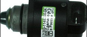
Location, purpose and device
The speed controller in the Lada Kalina car is a device made in a plastic case in the form of a cylinder. Inside the body there is a sensitive component that determines the speed of movement. As you can understand, the main purpose of the device is to accurately determine the speed limit.
Which speed sensor to buy on Priora: types of products
Priora is equipped with three types of speed sensors from the factory. This is important to consider before purchasing a new product. To avoid mistakes, you should first remove the product and, having copied the serial number (you can take a photo), buy a similar option. This approach will ensure that you do not make a mistake with your purchase and buy the right type of sensor.
The second note when buying a DSA for Priora is to choose only original products. Chinese devices may cost 100-200 rubles cheaper, but they may not only not be suitable for installation, as evidenced by the photo below, but also not work correctly (or not work at all).
If you bought a DS, but during installation it fits tightly into the hole, it means that the product was chosen incorrectly. Compare the diameters of the standard and new products, and only then install the part.
In order not to make a mistake with your choice and buy an original DSA for Priora, you should pay attention to the presence of the serial number:
- 2170-3843010-04;
- 2170-3843010-02;
- 2170-3843010.
The main difference between them is in the calibration (the type of signal perceived by the controller) and the shape of the working part where the semiconductor element is located. Choose the products correctly, as the correctness of their operation depends on this.