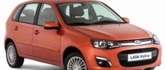
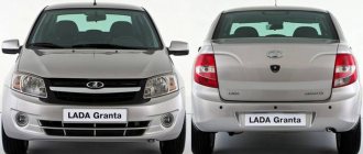
Complete information is provided about electrical equipment, wiring, relays and fuses of VAZ-2170 - VAZ-21728 vehicles. The collection is intended for auto electricians and those who, having some knowledge of circuit design, can carry out minor auto repairs with their own hands. The Lada Priora sedan (VAZ-2170) has been produced since 2007, the VAZ-2172 hatchback since 2008, and the VAZ-2171 station wagon has been produced since 2009. In 2013, the car was modernized and they began installing an AMT robotic gearbox (21723, 21728).
There are 4 main harnesses in the Priora electrical circuit:
- from the instrument panel;
- providing motor control;
- front electrical harness;
- rear electrical harness.
All these harnesses are connected to each other using detachable connections. The connectors are located under the dashboard. Each of the harnesses is assigned a serial number.
In addition to the main ones, there are also secondary ones:
- installed in the front passenger door;
- identical in both the left and right rear doors;
- installed in the driver's door;
- connecting the backlight of the license plate;
- connecting the electrical package.
Each element in the diagram corresponds to a number with an explanation. Since all elements are standardized, their designations are identical on car diagrams of all car manufacturers. Next to each electrical appliance, the connectors that go to them are indicated. The pins or sockets of the pads are also numbered.
Bright corner - LEDs • Interior lamps in Lada Priora
Let's shine a light on our favorite pepelats
Interior lamps in Lada Priora
RZ296 » Aug 28, 2011, 00:02
The car is a Lada Priora in the Lux configuration - two LED lamps, in the front there are two spot lights with 12 mm LEDs and one common with 3 piranhas, in the back there are only 2 spot lights. The spectrum, it should be noted, was neutral, without noticeable blue. The diodes worked in, presumably, prohibitive modes - 30 mA for the point ones and it’s unclear how much for the piranhas (two 33 Ohm resistors, it’s unclear what the drop on the diodes is, I didn’t measure it. First one of the piranhas died - the lamp blinked. Temporarily installed 4 segments LED strip on warm white diodes. Then, with a difference of 2 weeks, both rear diodes blinked. I ordered 3HP2C, removed the shades and began to remodel. From the dealextrimov ceiling lamp with 7 one-watts, embedded in a table lamp with the dismantling of the optics, 7 collimators with a diameter of 20 mm remained. I really didn’t want to glue the collimators with the front plane, but there was no other option, so I did the following: I ground off the tubes of the lamp housing protruding inward at an angle (the original diodes stood at an angle on plastic stands on the boards). In the photo, the left one has already been sawed off. I mounted 3 on the boards radiator made of AMCP sheet 2 mm thick: On the boards, the lead-out elements in the radiator area were raised above the boards so that the leads did not reach the back surface of the board. I glued the diodes onto the radiators with hot glue - one for the spot ones and 2 for the central ones (I also decided to add a central light at the back): I replaced the quenching resistors - with 2 point resistors connected in series with 47 Ohms each, and with central ones - two in parallel with 100 Ohms. The current through the diodes is about 100 mA, you don’t need much more, and there won’t be any problems due to the small area of the radiators. I did not install stabilizers due to the fact that smooth attenuation of light is implemented as standard, and with such a current reserve they are not needed. Installation using conventional MGTF. On the boards near the elements there is not flux, but remnants of the urethane varnish that was used to coat the board at the factory. A disgusting substance in terms of repair. I connected the rear light to the battery from a screwdriver and locked myself in the bathroom with it: I was happy to note that gluing the collimators to the body had virtually no effect on focusing. Now how it shines in the car: The result is excellent, nothing could be asked for better. The last photo shows an example of how the front passenger's spotlight shines. The footwells of the driver and front passenger are illuminated using strips of warm white diodes, switched on in parallel with the corresponding spotlights. RZ296 Flashlight Messages: 26 Registered: Aug 14, 2011, 07:32 pm From: Moscow region, Klimovsk Thanked: 0 times. Thanked: 3 times.
Checking the regulator for functionality
To diagnose DTOZH at home, you will need a separate container with antifreeze, as well as a thermometer that can record temperatures up to 120 degrees. Checking is carried out using a tester. In particular, you need to measure the resistance at different temperatures of the liquid (the liquid must be heated during diagnostics), and the obtained data is checked against the temperature.
At 100 degrees, the resistance of the device should be 177 ohms, at 90 degrees - 241 ohms, at 80 - 332 ohms. At an engine temperature of 0 degrees, the resistance level will be 7280 Ohms, at 40 degrees – 1459 Ohms. This data will be sufficient for diagnostics.
Wiring diagram for a VAZ 2114 car
Electrical wiring components
Lada largus fuse box A single-wire circuit (used for all electrical wiring) has negative consumer and source terminals, which are connected to the car body. The VAZ 2114 body is the second connector.
Complete circuit with electronics in VAZ 2114
Electrical wiring includes the following components:
- Block headlight.
- Anti-fog headlight.
- Temperature indicator.
- Mounting block housing.
- Electric fan motor in the engine cooling system.
- A block connected to the ignition system wiring group.
- Engine compartment light switch.
- Rear wiper motor connector plug.
- Devices.
- Car signal connection block.
- Electric motor for windshield wipers.
- Loudspeaker signaling device (SSU) housing.
- An indicator showing the volume of water in the glass washer.
- Front brake pad mode indicator.
- Oil quantity indicator.
- Generator and starter housing.
- Reversing headlight switching device.
- Lubricant pressure warning light indicator.
- Windshield wiper gear motor housing.
- Light housing under the hood.
- Engine coolant temperature indicator. 2x h16
Circuit breakers
In fact, the VAZ 2114 wiring is always connected to fuses. Such fuses do not protect only the circuit of the generator and charging device, the mechanism for switching on the power unit of the machine, as well as the winding of the backlight cut-off relay.
Before replacing a failed electrical circuit fuse, you need to find out exactly the reasons for the wiring overload, as well as its elimination. Finding the cause will be much easier if you first read the following materials. Below is a list of fuses and their purposes.
The data (the name of the fuse and the electrical circuit protected by it) shows a complete list of all possible wiring fuses. For each car, their number may differ.
- F1. Wiring diagram for the rear fog lights, electric motors for the headlight wipers, housing for the control lamp and its shutdown, electric motor for the headlight cleaner.
- F2. Turn signals and turn signal relays, hazard warning lights, hazard lights.
- F3. The wiring of the lamp illuminating the interior is customized depending on the personal preferences of the car owner, the ignition switch light, the car trunk light, the engine functionality check indicator, the on-board computer, the brake light indicator, and the clock.
- F4. A plug for connecting a portable lamp, a plug that connects the heating of the stern and rear windows.
- F5. Connection diagram for SGU, radiator propeller electric motor, VIP signal relay.
- F6. Power window relay, power window connection circuit. Fuse box in VAZ 2114
- F7. Wiring of the electric motor of the VAZ 2114 stove, electric motors for the headlight wipers and windshield washer, cigarette lighter circuit that illuminates the glove compartment, light bulb, relay for connecting the aft glazing heater winding.
- F8. Wiring diagram for the right fog lamp.
- F9. Left fog lamp diagram.
- F10. Electrical wiring for the side lights on the left side, an indicator that shows whether the side lights are on, a circuit for the engine compartment lamp, illumination of license plates, heating system levers and ashtrays, a cigarette lighter, a circuit for illuminating the switches.
- F11. Side lights located on the left side.
- F12. Right low beam design.
- F13. Left low beam design.
- F14. High beam device and left bulb. It is also an indicator for switching to high beam.
- F15. Right high beam design.
- F16. Wiring of turn signals, hazard light relay, relay responsible for the state of the lamps in the headlights, rear traffic indicator, lights signaling the following: low oil and brake fluid levels, whether the parking brake is on, low battery charge. Also a clock, an on-board computer and a generator excitation winding circuit during the start of the power unit of a VAZ 2114 car.
In addition to all the fuses listed above, which are located in the mounting block, there are 3 fuses. These fuses are located under the magazine shelf. The controller and relay circuit are also located here, with the help of which the VAZ 2114 power unit is controlled.
Blog about UAZ
Lighting control modules MUS 50.3769, 521.3769, 522.3769, 58.3769, 582.3769 are designed for switching electronic control circuits for external lighting, front and rear fog lights, adjusting the level of illumination of controls and devices, and controlling the angle of the light beam of auto headlights.
Lighting control module MUS 50.3769 for Lada Granta, VAZ-2190, Lada Kalina FL, VAZ-2192, VAZ-2194, properties, purpose of contacts.
Connecting the lighting control module MUS 50.3769 to the electrical equipment system of Lada Granta and Lada Kalina FL is done using block 1118-3724500.
The main properties of the lighting control module MUS 50.3769 for Lada Granta, VAZ-2190, Lada Kalina FL, VAZ-2192, VAZ-2194.
Rated voltage, V: 12 Rated overload: — Inductive: 110 mH; 0.5 A contact 56, 50 mH; 0.25 A contact 1 - Lamp: 10 A contact 58 and contact 3, 5A contact 4, 2.5 A contact 2 Color of the viewing surface: dark Color of signs: snow-white Color of backlighting of signs: green Dimensions, mm: 70x110x64 Weight, not the most , kg: 0.2
Numbering and purpose of contacts of the lighting control module MUS 50.3769 for Lada Granta, VAZ-2190, Lada Kalina FL, VAZ-2192, VAZ-2194.
G - not used. 56b - not used. 58b - not used. 31 - Mass. Xz - +12 Volts from terminal “15” of the ignition switch. 56 - to low beam lamps. 1 - Ground (signal for turning on side lights from the central body electronics unit) (only for MUS 50.3769-01). 2 - to the rear fog lights. 3 - to the front fog lights (only for MUS 50.3769-01, -02). 4 - to daytime running lights. 58 - to side lamps and device illumination sources. 30 - +12 Volts from terminal “30” of the ignition switch.
Lighting control modules MUS 521.3769, 522.3769 for Lada Priora, VAZ-2170, properties, purpose of contacts.
Connection of lighting control modules MUS 521.3769, 522.3769 to the Lada Priora electrical system is done using block 1118-3724500.
The main properties of lighting control modules MUS 521.3769, 522.3769 for Lada Priora, VAZ-2170.
Rated voltage, V: 12 Rated overload: - Active: 2 mA contact G - Capacitive, not less than 0.1 µF: 1-16 mA contact 2 (PTF), 1-40 mA contact 2 (ZPTF), 1-16 mA pin 4 (“+” brightness), 1-40 mA pin 4 (“-” brightness), overload is switched to pin 31 - Lamp: 10 A pin 56 and pin 58 Viewing surface color: dark Sign color: snow-white Sign backlight color: green Indicator backlight color: ZPTF - yellowish, PTF - green Dimensions, mm: 155x73x60 Weight, not more than, kg: 0.25
Numbering and purpose of contacts of lighting control modules MUS 521.3769, 522.3769 for Lada Priora, VAZ-2170.
G, 56b - to the gearmotor of the headlight range control. 58b - from illumination sources of controls and devices. 31 - Mass. Xz - +12 Volts from terminal “15” of the ignition switch. 56 - to the headlight low/high beam switch. 1 - from the rear fog lights. 2 - to the controller (turning on the rear/front fog lights). 3 - from front fog lights (only for MUS 522.3769). 4 - to the controller (adjusting the backlight level of devices). 58 - to side lamps. 30 - +12 Volts from terminal “30” of the ignition switch.
Lighting control modules MUS 58.3769, 582.3769 for Lada Priora FL, VAZ-2172, properties, purpose of contacts.
Connection of lighting control modules MUS 58.3769, 582.3769 to the electrical equipment system of Lada Priora FL is done using block 1118-3724500.
The main properties of lighting control modules MUS 58.3769, 582.3769 for Lada Priora FL, VAZ-2172.
Rated voltage, V: 12 Rated overload: - Active: 2 mA pin G, 0.0005-0.05 A pin 56b - Inductive: 0.25 A pin 2 and pin 4 - Tube: 10 A pin 56, 5 A pin 58, 2.5 A contact 58b Color of viewing surface: dark Color of signs: snow-white Color of illumination of signs: green Color of illumination of signaling devices: ZPTF - yellowish, PTF - greenish Dimensions, mm: 155x73x60 Weight, not more than, kg: 0.25
Numbering and purpose of contacts of lighting control modules MUS 58.3769, 582.3769 for Lada Priora FL, VAZ-2172.
G - to the gearmotor of the headlight range control. 56b - to the controller of the automatic lighting control system (only for MUS 582.3769). 58b - to sources of illumination of controls and devices. 31 - Mass. Xz - +12 Volts from terminal “15” of the ignition switch. 56 - to the headlight low/high beam switch. 1 - from the rear fog lights. 2 - to the rear fog lamp relay. 3 - from front fog lights (only for MUS 582.3769). 4 - to the front fog lamp relay (only for MUS 582.3769). 58 - to side lamps. 30 - +12 Volts from terminal “30” of the ignition switch.
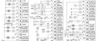
Pinout of the instrument panel VAZ 2170 Priora
The layout of the instrument panel is made in a simplified version to facilitate the replacement and installation of replacement parts. The decoding of the wiring connections at the factory terminals looks like this:
- 1 – EUR;
- 2 – emergency signal control;
- 3 – oil pressure sensor;
- 4 – indicator light for turning on the hand brake;
- 5 – immobilizer control unit;
- 6 – control unit for airbags;
- 7 – external lighting of the car;
- 8-9 – direction indicators;
- 10 – control of the combustible mixture injection system;
- 11 – disabling the front passenger SB;
- 12 – indication of seat belt buckles;
- 13 – operation of the brake system;
- 14 – reset button of the steering column switch;
- 15 – indication of the expansion tank of the brake system;
- 16 – ABS control unit;
- 17 – headlight high beam position switch;
- 18 – dashboard lighting;
- 19 – mass;
- 20 – receiving power from the battery terminal;
- 21 – ignition switch connector;
- 22 – fuel consumption sensor;
- 23-24 – BC mode switch;
- 25-26 – temperature sensor “overboard”;
- 27 – remaining fuel in the tank;
- 28 – speedometer;
- 29 – antifreeze temperature indication;
- 30 – tachometer;
- 31 – diagnostic terminal;
- 32 – power supply from generator (L).
Ideas for tuning and modifying the shield
VAZ 2110 dashboard: general information on icons How to tune the dashboard:
- Instead of a standard shield, install a more advanced one, with a navigator. In such devices, the arrangement of indicators and sensors will be different - the sensors are located on the right and left, and in the middle there is a navigator display. This tuning option is considered one of the most expensive.
- Install ready-made or develop your own scales for sensors. To implement this idea, you will need to completely remove the tidy and disassemble it, as well as disconnect the arrows from the sensors. The scales are installed on existing sensors and are securely fixed.
- Use of LEDs in lighting. The device will also have to be disassembled, but here the method is simpler. You don’t have to remove the arrows, you just need to turn off the light bulbs on the device and dismantle them, and then replace them with new ones. If the base of the light sources does not match, the lamps will have to be soldered. Alternatively, instead of light bulbs, you can solder an LED strip.
- Paint the dials and gauges of the instrument panel with fluorescent paint, but for greater effect, again, you will need to install diode lamps. With this combination, the tidy will glow brightly, but keep in mind that the implementation of this method requires care and painstakingness from the car owner.
Types of PTF
As you know, Priora underwent several stages of restyling, where one of the main changes was the bumpers. With the change in bumpers, the design of the PTFs themselves also changed.
In the old bumper, the fog lights had a round appearance, but in the new one they already received a frame in the shape of a triangle, but still with the same round headlight.
At first glance, you might think that they are exactly the same, but this is a wrong assumption; they have different mounting brackets. Therefore, it is important to know which bumper the PTF will be installed on.
There are two manufacturers of fog lights for Priora - BOSH and Kirzhach. It is difficult to notice any particular difference in the luminous flux of these manufacturers, but there are differences in the mounting for installation in them. It will be difficult to replace “BOSH” with “Kirzhach”; for this you will have to change the PTF spacer in the SE bumper.
There are two options for installing a pre-restyle Priora and a post-restyle Priora into the bumper (SE bumper, Priora 2).
Articles and price of PTF for PRIORA 1 (pre-restayl until 2012):
PTF Priora 1
PTF "Kirzhach": 21700-3743010-52. The price starts from 700 and reaches 1000 rubles. For one headlight, sellers ask from 500 rubles.
PTF "BOSCH": 21700-3743010-54. The price starts from 1500 and reaches 2000 rubles. For one headlight you will have to pay from 1000 rubles.
Articles and price of PTF for PRIORA 2 (restyled after September 2012):
PTF Priora 2 (with frame)
PTF "Kirzhach": 21700-3743010-53. The price starts from 800 and reaches 1100 rubles. For one headlight, sellers ask from 600 rubles.
PTF "BOSCH": 21700-3743010-50. The price starts from 1000 and reaches 1500 rubles. For one headlight you will have to pay from 700 rubles.
It should also be noted that not all stores come with a mounting kit of wires and relays for the PTF. It is necessary to check with the sellers whether they have an installation kit. Otherwise, you need to purchase it in addition. Its cost is from 600 rubles.
Analogs
If for some reason the models from and “Kirzhach” do not suit you, then you should not be upset. Currently, the market is simply filled with a huge number of Chinese-made analogues.
Manufacturers from China have a large selection of high-quality PTFs that are not inferior to more expensive models.
One of the most popular Chinese PTF models are headlights that completely cover the cutout for the fog lamp, that is, they have the shape of a triangle.
Connecting the interior lamp of the Priora
I would like to share with you my experience of installing rear passenger lighting. Installed due to lack of light from the driver's lamp. I often had to use a flashlight to find a bag or packages left in the back seat. I’ll make a reservation that the lampshade from the Priora Luxury is not too bright, so I’ll be finalizing it later and will definitely share my experience. But for now about the installation itself.
You need to purchase: - a lamp frame (130 rubles as of January 2017) - a lamp for illuminating the rear passengers (400-450 rubles) - 3 meters of wire (a thick wire is unnecessary here, since the power consumption of both lamps does not exceed 1A) - 3 pin connector (I didn’t find a native one for sale, so I used a computer 4 Pin (I’ll specify which one later) - 3 pin connector for connecting to the lampshade
And since I replaced the “standard” front lamp with a “luxury” one, I need two 3-pin blocks. I bought one in flames for 100 rubles (wow! for what?!). Then I looked in the bins and found a suitable 3 pin connector from the computer. This header connects to the motherboard and powers the Power LED on the case.
First, I cut off the connection block for the original lamp, because... I didn't find the answer to it.
Replacement and repair of the electrical package control unit 2170-3763040 Lada Priora
Modern versions of cars are supplied to the market with a restyled version of the tidy. Here, a relatively old generation, navigation and a liquid crystal display appeared. Installing an updated shield requires the following steps.
There are only two types of updated designs with and without a CAN bus. The nuance is that the versions are completely identical in appearance. In order to find out which variety is suitable, you need to check the production date of the car. Cars manufactured before 06, 2012 are not equipped with such technology. The article numbers of the new devices with navigation are as follows:
- 2170-3801010-50 without CAN;
- 2170-3801010-60 with CAN.
Read more: Electric power steering for the VAZ 2107: basic recommendations Also included in the kit is the need to purchase a navigation antenna and a steering column switch of the appropriate design.
Installation nuances
For Lada Kalina versions, all devices are not equipped with a CAN module. Also the old generation of Priora. Here the installation is carried out without modifications or nuances - just snap out the old panel, remove the terminals, and mount the new set on the stock fasteners. Next, you need to install a navigation antenna on the roof and connect it to the appropriate connector.
The second case is when an old panel with a CAN unit, but without navigation, is replaced with an analogue one. Here it is necessary to rearrange the contact connectors of the standard wiring from positions 10-11 to sockets No. 28-29. In case of incorrect operation of the devices, the replaced wires are swapped with each other. After the repair is completed, the counters should be reset to zero.
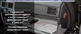
The electrical package controller is a device designed for installation on VAZ 2170 Priora cars. It controls many car functions, for example, turn signals, power windows, instrument panel lights, side lights, low beam, fog lights, reverse lamp, interior lighting, heated rear window.
This controller is installed in the central, lower part of the dashboard above the ECU unit. To remove it, you need to remove the lower sides of the torpedo. Using a socket wrench 10, unscrew the two nuts.
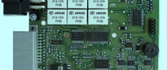
Priora electrical package control unit board 2170-3763040
Location of terminals of the Priora electrical package control unit 2170-3763040
Diagram of the Priora electrical package control unit 2170-3763040
POS - interior lighting lamp ZPTO - rear fog lights BS - low beam PTF - fog lights MDV - driver's door module PUP - turn signal switch PAS - hazard warning switch PPD - front right door PLD - front left door ZPD - rear right door ZLD - rear left door PS - passenger door power window switch FOB - trunk light ZP - right mirror ZL - left mirror GO - side lights UP - direction indicators
Messages 7
1 Topic by Admin 2013-07-05 13:09:37
- Admin
- Administrator
- Inactive
- Registration: 2012-02-20
- Messages: 3,257 Thanks : 624
Topic: Is it possible to connect the light control module from Priora to a VAZ 2110?
Ideally, I would like to get a working connection diagram for this module instead of the standard “decimal” ones that are on the instrument mask.
2 Reply from Serg 2013-11-02 14:17:26
- Serg
- Lada2111.rf fan
- Inactive
- Registration: 2013-07-29
- Messages: 830 Thanks : 363
- Car: 2111 dwg 2114 year 2008
Re: Is it possible to connect a light control module from Priora to a VAZ 2110?
Connecting a light control module from Priora
We have a module with one 12-pin connector (No., color in prior) wire purpose (function) 1 - orange-black - input indicating that the rear foglights are on 2 - orange-white - output controlling the activation of the rear + front foglights 3 - yellow - input indicating that the front ones are on prottumanok 4 - brown - output control the brightness of the backlight of the buttons 31 - black - ground (it is also mass in Africa) 30 - pink - input +12volts from the battery 56 - green - output +12volts turn on the head light 58 - whitechern - output +12volts turn on dimensions 56v - serkras - +12 volt input after turning on the head light to control the fog light 58v - white - input for the illumination of the Xz - synchern - +12 volts after the ignition switch G - blue - to control the headlight range control
56 Xz 31 58b 56b G 30 58 4 3 2 1
After comparison with the 2110-2112 scheme, the following came out:
1) it is possible to connect this unit without an electrical package control unit Priors without foglight controls (I will finalize it later) all other wires somehow match in color (.) must be connected to the connector (standard 2110) light control except for the following wires: 1 – orange-black, 2 – orange white, 3 – yellow, 4 – brown (use standard regulator 2110), G – blue (if you want to connect the headlight range control, knock on the priors)
2) it is possible to install a control unit for the Priora electrical package (but later)
3 Reply from Admin 2013-11-13 13:45:45
- Admin
- Administrator
- Inactive
- Registration: 2012-02-20
- Messages: 3,257 Thanks : 624
Re: Is it possible to connect a light control module from Priora to a VAZ 2110?
That is, here are the contacts of the ICC Priora that should be used? 31- black - ground (it is also mass in Africa) 30- pink - input +12 volts from the battery 56- green - output +12 volts turns on the head light 58- belchern - output +12 volts turns on the headlights 56v-serkras - input +12 volts after turning on the headlight light for control fog 58V - white - input to the Xz block illumination - synchern - +12 volts after the ignition switch
Here is the standard switch for the low beam and dimensions of the old-style instrument panel (on diagram No. 36)
30 (pink) - connect to 56 (green) 58 (white-black) - connect to 31 (black) 56 (green) - connect to 58 (belchern) X (blue-red) - this is also a mass.
I found the remaining contacts in the VAZ 2110 mounting block: Ш3-4 (+12V) - connect to 30 (pink) Ш3-1 or Ш3-3 - connect to 56V (serkras) Ш2-8 - connect to 58V (white) Ш1-4 and Ш4-17 - connect to Xz (synchern) Is that right?
I looked at the contacts from the mounting block here
4 Reply from Serg 2013-11-13 16:20:04 (2013-11-13 16:50:09 edited by Serg)
- Serg
- Lada2111.rf fan
- Inactive
- Registration: 2013-07-29
- Messages: 830 Thanks : 363
- Car: 2111 dwg 2114 year 2008
Re: Is it possible to connect a light control module from Priora to a VAZ 2110?
No, it’s not right on the standard light switch 2110 to connect all the wires in the same colors with the Priora IUS, something like this
Priora 2110-212 30 (pink) - connect to 30 (pink) 58 (white-black) - connect to 58 (belcher) 56 (green) - connect to 56 (green) X (blue-red) - X (blue-black) +12 volts after the ignition switch
The wires of the MUS Priors 1 - orange-black, 2 - orange-white, 3 - yellow, have a trigger switch (i.e. pressed once, turn on a second time, turn off) the triggers are located in the Priora's electrical package unit, so simply connecting them to 2110 will not work, you need to come up with a diagram
Additional brake light
The additional brake light uses LEDs instead of lamps. If the LEDs are faulty, the lamp assembly must be replaced. The work is shown on a hatchback car. On a sedan car, the light is secured to the rear window shelf from below with two screws from the luggage compartment.
Installing an additional brake light may require two new headliner brackets.
1. We prepare the car for work.
2. Having opened the tailgate, use a slotted screwdriver with a thin blade to remove two plugs from the housing of the additional brake light.
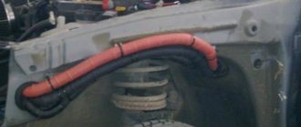
In addition to the flashlight wires, a rear window washer tube is routed through the corrugated hose. As a result, it is difficult to pull out the wires, much less re-stretch them together with the block.
6. Mark the colors of the wires on the block and use an awl or a screwdriver with a thin blade to release the wire retainer.
7. Remove the wire clamp from the block.
8. Use a needle or the end of a metal clip to tighten the tip lock and remove the wire tip from the block.
9. Similarly, remove the tip of the second wire from the block.
10. Remove the rubber seal from the door opening.
11. Pull the flashlight wires out of the corrugated hose.
12. Pull the wires out of the door hole.
13. Using an 8 mm socket wrench, unscrew the two nuts securing the additional brake light.
14. Remove the additional brake signal light from the car.
Install the additional brake signal light in the reverse order.
Warning!
We connect the wires to the block taking into account their color. You can check the correctness of the connection by focusing on the block of wires under the upholstery: the wires should be connected to the connector so that the red wire is located opposite the red one, and the black wire is opposite the black one.
Location of Priora fuses under the hood
- F1 (30 A) – power supply fuse for the electronic engine control system (ECM);
- F2 (60 A) – fuse for the power supply circuit of the engine cooling system fan (power circuit), additional relay (ignition relay), rear window heating, electrical package controller;
- F3 (60 A) – fuse for the power supply circuit of the electric fan of the engine cooling system (relay control circuit), sound signal, alarm signal, ignition switch, instrument cluster, interior lighting, brake light, cigarette lighter;
- F4, F6 (60 A) – generator power circuit fuses;
- F5 (50 A) – fuse for the power supply circuit of the electromechanical power steering
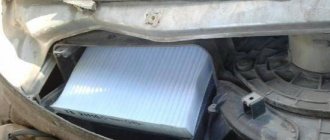
Relay and fuse box for Halla air conditioner
- right electric fan power supply fuse (30 A);
- fuse for the power supply circuit of the left electric fan (30 A).
- right electric fan relay;
- additional relay (sequential activation of left and right electric fans);
- left electric fan relay;
- heater fan power supply fuse (40 A);
- compressor power supply fuse (15 A);
- heater fan relay;
- compressor relay.
Panasonic air conditioner relay and fuse box
- Heater fan maximum speed
- Right fan
- Fan sequential relay (low speed)
- Left fan
- Left fan fuse (low speed)
- Right fan
- Heater fan
- Compressor
- Heater fan
- Compressor
Repair of the ICC
To repair the light control unit, you only need a little skill in using a soldering iron, the soldering iron itself and solder.
To repair the light unit, it must be dismantled.
Remove the fuse box cover by turning the three fasteners 90°.
We unscrew the screw securing the MUS, take it out and disconnect it from the chip.
Disassembling the module
Pull the switch up and remove it, then use a screwdriver to pry up the bottom of the switch and remove it.
Carefully bend the 4 plastic clips, be careful the plastic is not elastic and breaks easily.
We remove the front cover of the MUS and take out the board by pressing on the contacts from the back side, the board will rise. Do not use too much force to avoid damaging the board!
The light control unit is disassembled and you can start soldering. The photo shows the places that are most subject to load and are the culprits in the malfunction of the module; they need to be soldered.
After the contacts are soldered, it is recommended to clean the contact stain with a file or sandpaper.
After the repair, we assemble the module in the reverse order and install it in place.
As you can see, there is nothing complicated in repairing the light control unit.
Source
Instructions for replacing the tidy yourself
The procedure for removing, disassembling and replacing the control panel can be carried out on your own; there is nothing complicated about it.
How to remove the PP:
- First of all, turn off the ignition, and then disconnect the battery from the power supply.
- For greater convenience, you should remove the steering column cover, and also dismantle the steering wheel itself.
- After this, using a screwdriver, you need to unscrew the two screws that secure the upper part of the tidy.
- Next, two more screws are unscrewed, only now from the bottom.
- There are two more screws on the sides of the control panel; they also need to be unscrewed.
- After this, you can pull the tidy towards you, but do not remove it completely. Since wires are connected to the device, you need to disconnect the connectors on the back side, and then release the latch.
- The PP is removed and replaced with a new one. Assembly steps are carried out in reverse order.
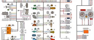
Electrical circuit operation
It runs on a gasoline engine with electronic ignition, and the power system of the Lada Priora is injection. Correct fuel supply is carried out thanks to an electrical controller, and the mixture is ignited using a regular spark. All other components of the Priora are not paramount, since they are designed to provide factors such as safety and comfort while driving. In general, the VAZ scheme is divided into 2 categories:
The electrical wiring diagram is based on detachable connections, due to which, in a fairly short period of time, not only diagnostics of any Priora breakdowns is carried out, but also troubleshooting.
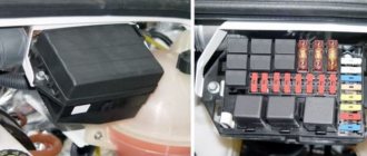
Fuse box in the passenger compartment of VAZ-2170, -2171, -2172
The fuse box in Priora is located at the bottom of the dashboard, on the left side of the steering wheel. To get to it, you need to open the cover, which is held on by three latches. Rotate each locking knob 90 degrees and pull the lid down and it will snap open.
Fuses in the interior mounting block
F1 (25 A) - radiator cooling fan. If your fan does not work, check its motor by applying 12 V directly to it from the battery. If the engine is working properly, then most likely the problem is in the wiring or connectors. Check the serviceability of relay K1.
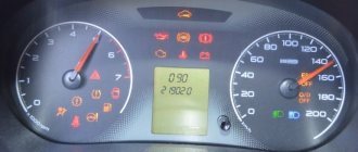
The fan in the Priora usually turns on at a temperature of 105-110 degrees. Do not allow the engine to overheat, watch the arrow of the temperature sensor.
If the fan runs constantly and does not turn off, check the coolant temperature sensor located on the thermostat. If you remove the connector from the working sensor, the fan should turn on. Check the wiring to this temperature sensor, as well as the contacts of relay K1, move this relay, clean the contacts. If this is the case, replace it with a new relay.
F3 (10 A) - high beam, right headlight. F4 (10 A) - high beam, left headlight. If the headlights do not shine on high beam, check the K7 relay and the headlight bulbs. The steering column switch, wiring or connectors may also be faulty.
F5 (10 A) - sound signal.
If the signal does not work when you press the steering wheel button, check relay K8. The signal itself is located under the radiator grille; you can get to it by removing the plastic casing from above. Check it by connecting the voltage to 12 V. If it doesn’t work, try turning the adjusting screw, or replace it with a new one.
F6 (7.5 A) - low beam, left headlight. F7 (7.5 A) - low beam, right headlight. When replacing lamps, be careful; there are separate lamps for the low and high beams, so they can be easily confused. It is better not to install lamps in high-power headlights; the reflectors may melt and the desired effect will not be achieved. Most low beam headlight problems that cannot be corrected by conventional means can be related to the light control module (LCM). The low beam relay is only available in cars equipped with a light sensor, it is located in the place of relay K1; on most cars this relay is not in the mounting block; the low beam circuit goes through the MUS block. It happens that the tracks in the block burn out; if there are problems, it is better to replace it with a new one. If the windshield wipers turn on spontaneously when the low beam is not working correctly, the problem is most likely in the windshield wiper control unit, located in the center of the dashboard, the topmost block, next to the radio, is best reached from the glove compartment, or by hand through the removed console covers at the feet.
F8 (10 A) - alarm signal. If the alarm does not work, also check relay K9.
F9 (25 A) - stove fan.
If your stove does not work in any mode, the problem may be with the stove speed controller or with the engine. Check the stove motor by applying 12 V voltage directly to it. If it does not work, remove it, open the cover and check the condition of the brushes. If the stove does not work only in the first modes, but works in the last mode, most likely you need to replace the heater resistance, located under the hood on the fan scroll.
The price of these resistors is about 200 rubles. Also check that the filter and all pipes are clean and that air flows normally into the stove. If the stove fan squeaks or turns with difficulty, try lubricating it. If the stove turns on and off, check the connectors and contacts in them, they could have melted or oxidized, in this case, replace the connector.
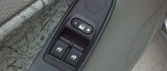
Procedure when the window regulator does not work
The design of the Priora's window regulators differs from the usual ones, which use a relay and a window regulator fuse. AvtoVAZ made the glass control using an electrical package control controller (TSBKE), which is located near the ECU.
1. Check the TsBKE fuse in the mounting block (F31, 30A).
2. Remove the door trim and check the voltage at the power window motor terminals using a multimeter or a 12V test lamp.
If there is no voltage, then check the serviceability:
- window control unit (buttons in doors)
- wiring (connector connection)
- electrical package control unit, which is located above the ECU unit (more on this below)
If current flows to the electric motor, but the glass does not move, then we check:
- malfunction of the window lift motor (for example, the drive motor brushes are stuck/sticking, the plastic gear in the gearbox is worn out)
- The window lift cable is frayed
- glass is jammed (distorted)
The most common problems with power windows are:
- Faulty double-glazed window control unit (GCU)
- Window lift motor malfunction
- Skewed, broken power window cable
- Poor contact
Opel Astra TURBO RESTYLING › Logbook › Replacement of interior lighting lamps!
Hello to all readers of my logbook!))) It’s immediately clear that the yellow light in the car is nothing... I decided to replace the standard lamps with LEDs! They were replaced a long time ago, but I just couldn’t get it together, choose the time and create a BZ...))) I bought 5 baseless LEDs for the lampshades, 4 LEDs for illuminating the sun visors
Then I took the lights apart. Disassembling the lights is simple, all fastenings are snapped, carefully pry and remove...
I didn’t install a central LED, because I don’t need light when opening the door, and in the future the lights for the legs and doors will be connected to this connector, but more on that in the next blog…)))
Then we put everything together and here is the result:
The central section does not light up, only the outer sections light up. There is plenty of light...
Then we move on to the rear courtesy lamp. Everything is sorted out and changed in exactly the same way...
Then we move on to illuminating the glove compartment. The yellow light in it doesn’t inspire me either... So I took out the flashlight, pulled out the old lamp and inserted a new diode... To pull out the flashlight you need to pry it off with a flat screwdriver, as if from the inside...
The only thing left to do is to replace the lamps in the sun visors... As with all lampshades, it is extremely simple... The glass is removed, the lamp is taken out and the diode is installed... But there were some problems, the diodes were larger than the original lamps, so they had to be filed a little))) Unfortunately there are no photos of the finalization...
I immediately thought that the diodes would produce less light, but it turned out to be the opposite... Overall, I’m very pleased with the result, white light is much nicer!))) Don’t forget to comment and like!))) If you like it, of course!))) Thank you all for your attention! )))
Price: 500 ₽ Mileage: 1000 km