Work on the car continues...
We fix little mistakes, to be honest, I’m tired)
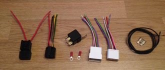
Here is one of the improvements:
I got busy with the wiring, extended the braid onto the forks and also hid the rest of the wiring in the normal way in the corrugation (no photo)
We remove collective farm wires on twists))
We solder the wires to the standard (exactly the same as they should be, we even chose the same color)
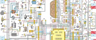
The electrical circuit is of great importance for the VAZ-2110 (8-valve injector) - it powers the entire on-board network. Consumers of different capacities are powered by a battery and a generator (they operate in parallel). On carburetor engines there is no control unit, sensors, or electric fuel pump, so the wiring is slightly different from that used in injection designs. But they still have common features.
Pinout of diagnostic connector for VAZ cars
VAZ cars have a fault diagnostic system that allows you to read and decipher error codes. Most VAZ-2110 cars have an old type “January-4” controller installed. The activation of “CHECK ENGINE” is considered a malfunction detection signal. Troubleshooting in such a controller is simple - error codes are calculated starting from the number 12 and ending with 61. For more modern VAZ models, ELM-327 electronic adapters with the OBD-II program are suitable.
Interior heating system
The VAZ-2110 stove consists of a radiator, fan, and air duct system. Using a fan, the radiator is blown and air (hot) is supplied to special channels. The electrical circuit of the VAZ-2110 heater also includes a damper position regulator. In essence, this is a regular stepper motor.
It allows you to move the damper, changing the angle of its opening, as well as the amount of cold air entering the heater from outside. The blower fan electric motor is connected through a specially designed switch. It has several positions, each of which corresponds to a specific rotation speed.
The fan speed is adjusted using resistances installed in the heater housing. These resistances are included in the power supply circuit of the electric motor. Switching occurs using a regulator installed on the instrument panel. On older cars of the tenth family you can still find mechanical damper drives. Similar designs are also found on “nines” and “eights”.
Where is the diagnostic connector located?
On different cars of the VAZ family, the socket is located in different parts of the car. Let's look at a few models as an example:
- on the VAZ-2112 , as on the 2110 , as well as the 2111 , the socket is located to the right of the driver’s seat, immediately under the column;
- on models 2108 , 2109 and 21099 , the socket you need is located under the glove compartment, on a special shelf;
- on cars with a europanel it can be found in the center of the console, near the cigarette lighter. A special decorative cover is used to disguise it;
- Lada Kalina cars the connector is near the gear shift lever, it is also hidden under a special cover;
- On a Lada Priora, look right behind the glove compartment, on the wall.
VAZ 2110
Price list
- Special offers
- KAMAZ spare parts
- Spare parts KAMAZ-5490
- Spare parts MAZ, YaMZ
- ZIL spare parts
- Spare parts ZMZ, for GAZ vehicles
- Spare parts for Volzhanki cars
- Spare parts for Gazelists
- Spare parts for trucks Lawns
- Spare parts for GAZ-71 caterpillar
- Spare parts UAZ, UMZ
- Spare parts KrAZ, BelAZ
- Spare parts URAL
- Spare parts BUSES
- AMAZ spare parts
- IKARUS spare parts
- KAVZ spare parts
- LAZ spare parts
- LIAZ spare parts
- NEFAZ spare parts
- PAZ spare parts
- Other buses
- Tractors, computer equipment, attachments
- Tractors and walk-behind tractors
- Municipal vehicles
- Attachments and trailed equipment
- Spare parts for TRACTORS and SPECIAL EQUIPMENT
- JCB - spare parts for special equipment
- Truck crane (KS-3577, KS-4517, etc.)
- AMZ (A-01, A-41, D-440, D-442, D-447, D-461, D-467)
- Amkodor (TO-18, TO-28, TO-30, etc.)
- ATZ (T-4A, TT-4M)
- VgTZ (DT-75)
- VMTZ (D-120, D-144, D-130, D-145T)
- VTZ (T-25, T30A-80, VTZ-2048)
- LTZ (T-40, LTZ-55, LTZ-60)
- MKSM, UNC, DETVAN
- MTZ - spare parts for tractors
- OTZ (TDT-55)
- PTZ (K-700/701/702/703/704)
- KhTZ (T-150, MT-LB)
- ChTZ (T-130, T-170, B-10, B-12, B-170, T-10M, DET-250)
- YuMZ - spare parts for tractors
- Other special equipment and tractors
- RVD - high pressure hoses and sleeves
- MMZ spare parts and engines
How to diagnose a car
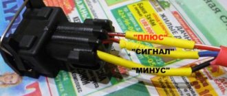
- Connect contact “B”, which has the diagnostic block and “ground”;
- Turn the ignition key to the third position, do not start the car;
- First, the “CHECK ENGINE” lamp displays code 12 with 3 flashes. It shows that the diagnostic programs are working. On the VAZ 2110 this happens in this order: the lamp blinks briefly 1 time (which should be considered the designation of number 1). After a pause lasting at least 2 seconds, it flashes 2 times in a row (two). So we got the number two. And this is repeated 3 times so that the driver understands these signs;
- After the diagnostic program has declared its serviceability, it will begin to display error codes, if there are any, of course. In the same way - flashes and pauses.
Symptoms of a problem
Quite often, injectors fail due to winding burnout or contamination, which seriously affects engine performance. If in the first case the injector fails completely and it is difficult not to notice, then in the second case, if it is dirty, it is quite difficult to determine whether the injector is faulty, but still it will show signs by which you can find out whether the injector is working or not.
Signs of a broken injector:
- The engine is tripping;
- Loss of power;
- The car's dynamics disappeared;
- The internal combustion engine starts poorly;
All these symptoms are indirect and can be observed with other problems in the car; in order to more accurately determine faults in the injectors, it is necessary to diagnose them.
Deciphering error codes
The first character is a letter and indicates a fault block:
- B - body;
- C - suspension;
- P — engine (ECM, gearbox);
- U - data exchange bus.
The second character is a number, code type:
- 0 — SAE (standard);
- 1.2 - OEM (factory);
- 3 - reserved.
The third character is a number, system:
- 1, 2 - fuel system;
- 3 - ignition system;
- 4 — reduction of exhaust gas toxicity;
- 5 - idle;
- 6 - ECU or its circuits;
- 7, 8 — transmission (automatic transmission).
The fourth and fifth characters are numbers, the error code itself.
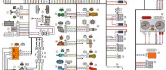
Diagram of VAZ 2110 injector 16 valves
1 - headlight 35 - instrument lighting switch 2 - front brake pad wear sensors 36 - ignition switch 3 - reverse light switch 37 - mounting block 4 - engine cooling fan electric motor 38 - recirculation valve switch 5 - sound signal 39 - controller heater 6 - right front door locking motor 40 - hazard warning switch 7 - power window relay 41 - heater control lever illumination lamp 8 - 8 A fuse 42 - glove compartment lighting lamp 9 - starter 43 - glove compartment lighting lamp switch 10 - battery 44 - cigarette lighter 11 - generator 45 - on-board control system display unit 12 - windshield washer motor 46 - ashtray lighting lamp 13 - washer fluid level sensor 47 - brake signal switch 14 - left front door locking motor 48 - locking motor left rear door 15 — power window switch of the left front door 49 — power window switch of the left rear door 16 — coolant level sensor 50 — power window motor of the left rear door 17 — windshield wiper motor 51 — socket for a portable lamp 18 — recirculation valve 52 — clock 19 - micromotor gearbox for heater flap drive 53 - gearmotor for electric window lift on the right rear door 20 - electric motor for heater 54 - power window switch at the right rear door 21 - trunk lock switch 55 - gearmotor for locking the right rear door 22 - power window switch at the right front door 56 - side turn signal 23 - electric window motor of the right front door 57 - parking brake warning lamp switch 24 - door lock system control unit 58 - driver's seat belt sensor 25 - additional heater motor resistor 59 - directional light bulb 26 - brake fluid level sensor 60 - interior light bulb 27 - electric window motor of the left front door 61 — interior air temperature sensor 28 — exterior lighting switch 62 — switch in the front door pillar 29 — instrument cluster 63 — switch in the rear door pillar 30 — rear fog light switch 64 — external rear light 31 — warning lamp fog light 65 - interior rear light 32 - rear window heating indicator light 66 - license plate lights 33 - rear window heating switch 67 - trunk light 34 - steering column switch A - blocks for connecting the rear window washer motor B - blocks for connecting the harness injection system C - to the warning light harness block D - block for connection to the on-board computer E - to the headlight cleaner harness block F - block for connection to the fuel level sensor in the electric fuel pump module G - to the rear window heating element H - block for connecting an additional signal braking J - to the trunk lock motor
How the injector wiring should work, how to connect it yourself
When deciding to make major modifications to their car, or restoring it after serious breakdowns, many motorists are faced with the need to replace the wiring. In the design of any car, it is possible to replace either the under-hood wires, mainly coming from the injector, or the interior electronics that ensure the operation of application devices. In today’s article we will look at the features of repairing and replacing both types of wiring, taking VAZ cars as an example. Interesting? Then be sure to read the article below to the end.
How to replace injectors on a VAZ 2108-VAZ 21099
The video shows design features, performance on the stand, cleaning and application of different ones.
https://youtube.com/watch?v=2lX9fJXOk_s
All four injectors are removed and installed identically, so for clarity, we will show the removal of only one injector!
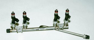
1) At the very beginning of the operation, remove the fuel rail from your vehicle. (How to remove the rail, see the article: “Replacing the fuel rail”)
2) When the ramp is removed, place it on a flat surface and then disconnect the wire block from the injector you need.
In order to disconnect the wiring block, squeeze the spring clip that secures it and only then disconnect it!
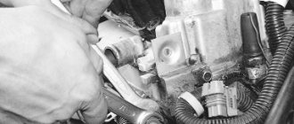
3) Now, using a screwdriver, move the metal clamp that secures the fuel injector in the direction of the ramp.
There is no need to completely remove the clamp from the ramp, just moving it to the side is enough!
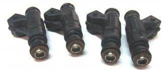
4) Next, grab the nozzle with your hand and shake it, as a result of which you remove it from the ramp.
5) Next, check the condition of the sealing ring of the injector body and the sealing ring of the spray part of the fuel injector, for this:
Taking a screwdriver in your hands, use it to pry off both o-rings and check their condition.
If the rings are in good condition, then in this case they can not be thrown away, but left as a spare and later used on a new injector. Before installing old rings, be sure to lubricate them with engine oil!
Installation of new injectors occurs in the reverse order, that is:
1) First, check the condition of the injector O-rings.
The condition of the rings is checked only if you are going to install a used injector on your car!
2) Next, the fuel injector is inserted into the hole in the ramp, and after installation it is fixed with a clamp.
3) And finally, a block of wires is connected to the fuel injector, and after connection, the fuel rail is installed in its place.
Additional video materials:
Below you will find a video in which the replacement of fuel injectors will be carried out in detail. And the most important thing is that the replacement will be carried out quickly, that is, without removing the throttle assembly, in general, watch the video:
Features of injection wiring
The appearance of an injection engine power system was marked by a real breakthrough in the automotive industry. Not only have cars with internal combustion engines begun to consume noticeably less fuel, but it has also become possible to fine-tune them to a specific operating mode by adjusting the injectors. However, this state of affairs also affected the complexity of building vehicles. More precisely, the number of different electronics in the design of an injection car has become noticeably larger, and the wiring diagrams have become much more complicated.
This is due to the fact that the injector is a fine-tuning unit that requires broad information about the operation of many vehicle components. This aspect of the functioning of the injection system affected the addition of many sensors to its structure, working in conjunction with the head unit (electronic control unit). To clarify this point, we highlight the following new devices in the design of injection machines:
- Crankshaft position sensor, necessary to regulate fuel injection into the engine;
- Mass air flow sensor installed to adjust the composition of the fuel mixture;
- Knock sensor, with which the ignition timing is adjusted;
- Throttle position sensor, required for the injector to respond to pressing the gas pedal;
- Idle speed regulator, responsible for stable operation of the engine at idle speed;
- Temperature sensor that evaluates the temperature of antifreeze in the engine;
- A speed sensor, thanks to which the electronic control unit (hereinafter referred to as the ECU) selects the composition of the fuel mixture.
In addition to the general complication of the system, there were some simplifications in the design of the car. Perhaps the main one was the elimination of some elements of the ignition system. To be more precise, the distributor and coil have become more primitive components, being responsible solely for spark generation, while control of the spark supply has completely passed to the ECU.
Note that the complexity of the interior and engine compartment wiring of cars depends on many factors. The main ones include the make of the car and the equipment of a particular model. That is, the more functionally equipped a car is, the more electronics there are in its design and the more complex its connection diagram. In today's material, our resource decided to consider a not particularly complex system for connecting the wiring of the injector and other devices on VAZ cars. We'll talk about this in more detail later.
Repair
Before removing the injectors from the dismantled rack, it is advisable to check their functionality. To check you will need:
- four identical containers,
- tester,
- wires.
Functionality check
- Connect the gasoline supply and drain hoses and the power connector to the rail with injectors.
- Place the rack over the measuring cups.
Place the rack over the measuring cups
The shape of the cloud should be approximately the same for all nozzles
After the war, Germany received a ban on the development of injectors for aircraft engines. And engineers began adapting direct injection systems for passenger cars, discovering another important advantage compared to carburetors - efficiency.
Vladimir Berestenev
Replacement or flushing?
Some problems can be eliminated by cleaning and flushing. Others are “treated” only by replacement.
Table: problems with injectors
| Malfunction | Remedy |
| reduced performance | flushing, replacement if flushing fails |
| leakage | flushing, replacement if flushing fails |
| increased productivity | replacement |
| valve sticking | replacement |
| unstable valve sticking | flushing, replacement if flushing fails |
| overestimated or underestimated winding resistance | replacement |
In these cases, flushing is not a panacea. This method should be used taking into account the mileage and quality of service during operation.
During operation, the injector nozzles inevitably become coked and clogged with resinous deposits. The picture is aggravated by low-quality fuel, which can introduce additional pollutants.
For some time, fuel atomizers continue to operate without any visible changes, but sooner or later contaminants accumulate, changing the shape of the spray and reducing performance.
Injector life expectancy is limited even when using the cleanest fuel. Manufacturers recommend changing them every 100–120 thousand kilometers. Due to the fact that motorists use imperfect gasoline, and the one that can be bought at gas stations, the part has to be changed after 80-100 thousand km.
There is an opinion among motorists that “there is no need to interfere if everything works fine.” This opinion is justified, but only if the owner is ready to replace the nozzles with new ones approximately every 50 thousand kilometers.
The fact is that by getting rid of minor deposits as they accumulate, the owner extends the life of the consumable, since pollutants do not have time to cause irreparable damage.
Clogged injectors begin to interfere with normal operation after 30–50 thousand km. Initially, negative processes manifest themselves only in increased fuel consumption. Owners do not always associate the increased “appetite” of the engine with injectors, since there are many reasons for this phenomenon.
Basic tips for working with automotive electronics
Let’s immediately agree that installation, removal and any other work with car wiring are the most complex operations, which are taught in secondary specialized educational institutions. This article is for informational purposes only on working with the electronics of VAZ models and contains solely a description of the basic aspects of these procedures, so it will not be possible to learn from it all the intricacies of wiring repairs. Familiarization with these lies only through long and hard work associated with work practice in the field of automobile repair.
Step-by-step replacement instructions
You can check the condition of the sensor in different ways, but specialists at a service station can do this better and more accurately. Before checking, of course, it needs to be removed and this is done very simply and even a novice car enthusiast can do it. If you are sure that the sensor is not working correctly, you can also replace it yourself.
- Turn off the ignition.
- Raise the hood cover.
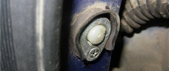
- Find where the sensor is installed.
- If it and the place where it is installed are very dirty, then you must clean it with a rag or brush.
- We remove the block.
Removing the block from the connector Unscrew the bolt.
Unscrew the fastening bolt. Remove the shaft position sensor.
We take out the required part
We check the generator drive toothed pulley for damage and other malfunctions. This is very important because if it becomes damaged, data will not be transferred correctly. Before installing a new sensor, clean the installation site. We install a new one or an old one, if you determine that it is working. Tighten the bolt. In this case, it is necessary to strictly control that the moment is not higher than 8-12 Newton meters. Using a feeler gauge, we control the gap between the pulley and the DPKV core. It should not exceed one millimeter. The maximum deviation is 0.4 mm in the direction of increase.
Required clearance
Let's start the engine. If it starts confidently, and the operation of the VAZ 2114 power unit is stable, then we can state that the work was done correctly.
As you can see, there is nothing complicated and you shouldn’t go to a service station unless absolutely necessary, spending extra money.