Main dimensions of valves, guides and valve seats
Details of the valve mechanism: 1 - valve; 2 - retaining ring; 3 - guide sleeve; 4 — oil deflector cap; 5 — support washer of the outer spring; 6 — lock washer of the internal spring; 7 — internal spring; 8 — outer spring; 9 — spring plate; 10 - crackers; 11 — valve drive lever; 12 — lever spring; 13 — adjusting bolt; 14 — lock nut of the adjusting bolt; 15 — bushing of the adjusting bolt; 16 — lever spring locking plate
Basic data for checking the outer (a) and inner (b) valve spring
We remove the cylinder head to replace the gasket, repair the valve drive mechanism and the head itself, as well as when completely disassembling the engine.
To replace the head gasket or connecting rod-piston group of the engine, remove the cylinder head from the engine complete with the receiver, intake pipe and exhaust manifold.
To remove the cylinder head:
- disconnect the negative cable of the battery;
- drain the coolant (see here);
- remove the throttle assembly assembly (see here);
- disconnect the hoses from the outlet pipe of the cooling jacket;
- disconnect the hose from the heater radiator inlet pipe;
- disconnect the fuel rail injector wire connector (see here);
- disconnect the connectors from the coolant temperature sensor of the injection system and the coolant temperature indicator sensor;
- remove the tips of the high-voltage wires from the spark plugs;
- disconnect the fuel inlet and outlet pipes from the fuel rail;
- disconnect the exhaust pipe from the exhaust manifold (see here), the heat shield of the starter and the bracket for the heater radiator outlet pipe (see here);
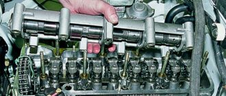
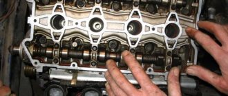
- remove the camshaft and valve drive levers (see here);
- remove the camshaft sprocket and tie the chain with wire.
Using a 13mm socket, unscrew the cylinder head mounting bolt located next to the ignition module bracket.
Using a 12mm socket, unscrew the ten bolts securing the head to the cylinder block.
Remove the cylinder head assembly with the exhaust manifold, receiver and intake pipe with the fuel rail.
The cylinder head can also be removed from the engine by first dismantling the receiver (see here), the intake pipe and the exhaust manifold (see here).
Remove the cylinder head without the exhaust manifold and intake pipe.
Remove the cylinder head gasket.
We install the cylinder head on the workbench.
Using a 10mm socket, unscrew the two nuts securing the heater radiator inlet pipe to the block head.
Remove the sealing gasket.
Using a 13mm socket, unscrew the two nuts securing the outlet pipe of the cooling system jacket.
. and remove the pipe with the coolant temperature sensor of the injection system.
Remove the sealing gasket of the pipe.
When disassembling the valve mechanism.
. We place a stop - a wooden block - under the plate of the valve being desiccated.
We dry out the valve (see here).
. and remove the valve from the guide sleeve of the cylinder head.
We dismantle the other valves in the same way.
We assemble and install the cylinder head in the reverse order. Before installing the valves, clean them from carbon deposits and lubricate the valve stems with engine oil.
Assembling the valve mechanism.
. We strike the ends of the valves with a hammer with a plastic striker for more reliable fixation of the crackers (the wooden stop must be removed from under the valve plate).
Before installing the cooling system pipes, we clean the mating surfaces of the pipes and the block head from the remains of old gaskets.
We install new pipe gaskets, applying a thin layer of sealant to them.
We clean the mating surfaces of the head and cylinder block from the remains of the old gasket, dirt and oil.
Using a syringe with a needle or a rubber bulb, remove oil and coolant from the mounting holes of the cylinder block.
We install the gasket and cylinder head using two centering bushings.
When installing the head on the cylinder block, we pass the chain by the wire through the hole in the head.
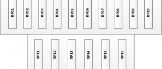
Having installed the cylinder head bolts, tighten them in the order shown in the figure.
To ensure a reliable seal and eliminate the need to tighten the bolts during vehicle maintenance, tighten the bolts in four steps:
1st step – tighten bolts 1–10 to a torque of 20 N.m (2.0 kgf.m); 2nd step - tighten bolts 1–10 with a torque of 69.4–85.7 N.m (7.1–8.7 kgf.m), and bolt 11 with a torque of 31.4–39.1 N.m ( 3.2–4.60 kgf.m). Then we turn bolts 1–10 by 90° (3rd step) and another 90° (4th step).
Removing, replacing, installing cylinder head gasket
Directory
Tags
Removing, replacing, installing anti-roll bar
Removing, replacing, installing timing belt
Removing, replacing, installing rear suspension shock absorber spring
Inspection, checking the steering
Removal, replacement, installation of the crankshaft and its bearings
Symptoms: oil leaking from under the cylinder head.
Possible cause: The cylinder head gasket is worn out.
Tools: set of wrenches, set of screwdrivers, sliding pliers, torque wrench.
Note. It is most convenient to dismantle the engine cylinder head complete with carburetor and manifolds (intake and exhaust).
1. Place the car on an inspection hole or overpass.
2. To make work easier, remove the battery from the vehicle.
3. Drain the working fluid from the engine cooling system.
4. Remove the wire end from the electrical connector of the coolant temperature gauge sensor.
5. Disconnect the exhaust manifold and the exhaust pipe.
6. Remove the air filter housing from the vehicle.
7. Disconnect the choke drive rod from the carburetor, then disconnect the fuel hose, then the crankcase ventilation hose, and then the vacuum ignition timing regulator. Disconnect the wire block from the solenoid valve.
8. Set the piston of the fourth cylinder to the top dead center of the compression stroke.
9. Dismantle the bearing housing assembled with the camshaft, and also do not forget to mark the position of the valve drive levers. After this, remove the valve drive levers along with the springs.
10. Using a wire, tie a chain and pass it through the window made in the engine cylinder head.
11. Remove the ignition distributor along with the high voltage wires.
12. Remove the spark plugs from the spark plug holes.
13. Remove the top nut securing the starter heat shield.
14. Remove the ground wire tip from the pin screwed into the intake manifold.
15. Remove the heating hose from the inlet pipe fitting.
16. Remove the brake system vacuum booster hose from the intake manifold fitting.
17. Loosen the clamps, and then remove the thermostat bypass hose, as well as the radiator inlet hose of the engine cooling system.
18. Disconnect the coolant supply hose to the heater radiator from the pipe, having first loosened the tightening of its mounting clamp.
19. Using a 12mm socket wrench and extension, remove the ten internal bolts securing the cylinder head to the engine block.
20. Using a 13mm socket wrench, unscrew the outer bolt securing the cylinder head to the engine cylinder block.
21. Remove the engine cylinder head assembly with the intake and exhaust manifolds, as well as the carburetor, from the vehicle.
22. Remove the gasket for the seal between the BC and cylinder head from the two centering bushings.
23. Install a new gasket and then the head onto the engine cylinder block in the reverse order, passing a wire and chain through the windows.
24. Check that the marks match.
25. Before screwing in the cylinder head mounting bolts, lubricate them with engine oil and wait at least 30 minutes. This is necessary so that excess oil drains from them.
Note. Reuse of old cylinder head mounting bolts is permitted only if they have not been stretched to a length exceeding 115.5 millimeters. If the length exceeds the specified value, the bolts must be replaced with new ones.
26. Tighten the cylinder head mounting bolts in four steps:
– pre-tighten the cylinder head mounting bolts to a torque of 20 N∙m;
– tighten the bolts to a torque of 69.4 N∙m;
– tighten the bolts 90 degrees;
– tighten the bolts again by 90 degrees.
27. Install the bearing housing and camshaft assembly onto the engine head studs, and then tighten the mounting nuts evenly.
28. Untie the wire, and then install the sprocket pulley along with the chain on the camshaft. Screw in the sprocket mounting bolt, then lock it by bending the tab of the lock washer.
29. Charge the timing chain tensioner, then install it in its original place, and then discharge it again.
30. Adjust the drive chain.
31. Adjust the clearances in the valve drive.
32. Adjust the generator drive belt.
33. Install the ignition distributor by directing the contact of the slider to the high-voltage terminal of the fourth cylinder.
34. Check and, if necessary, adjust the ignition timing.
35. Install all removed parts in reverse order.
36. Charge the engine cooling system.
content .. 1011 12 ..
VAZ-21213 (Niva). Tightening torques for threaded connections
GENERAL INFORMATION Part
| Thread | Tightening torque, N m (kgf m) | |
| Engine | ||
| Main bearing cap bolt | M10x1.25 | 68,31 – 84,38 (6,97 – 8,61) |
| Oil pump mounting bolt | M6 | 5,10 – 8,20 (0,52 – 0,85) |
| Breather cover mounting stud | M8 | 12,7 – 20,6 (1,3 – 2,1) |
| Breather cover nut | M8 | 12,7 – 20,6 (1,3 – 2,1) |
| Cylinder head bolt | M12x1.25 | see subsection 2.4. |
| Cylinder head bolt | M8 | 31,36 – 39,1 (3,2 – 3,99) |
| Nut of the stud fastening the inlet and outlet pipelines | M8 | 20,87 – 25,77 (2,13 – 2,63) |
| Connecting rod cap bolt nut | M9x1 | 43,32 – 53,51 (4,42 – 5,46) |
| Flywheel bolt | M10x1.25 | 60,96 – 87,42 (6,22 – 8,92) |
| Chain tensioner shoe bolt | M10x1.25 | 41,2 – 51,0 (4,2 – 5,2) |
| Cylinder head cover bolt | M6 | 1,96 – 4,60 (0,20 – 0,47) |
| Camshaft bearing housing nut | M8 | 18,33 – 22,64 (1,87 – 2,3) |
| Oil pump drive shaft sprocket bolt | M10x1.25 | 41,2 – 51,0 (4,2 – 5,2) |
| Camshaft sprocket bolt | M10x1.25 | 41,2 – 51,0 (4,2 – 5,2) |
| Valve adjusting bolt nut | M10x1.25 | 43,3 – 53,5 (4,42 – 5,46) |
| Valve adjusting bolt bushing | M18x1.5 | 83,3 – 102,9 (8,5 – 10,5) |
| Spark plug | M14x1.25 | 30,67 – 39 (3,13 – 3,99) |
| Coolant pump mounting bolt | M8 | 21,66 – 26,75 (2,21 – 2,73) |
| Cooling jacket outlet pipe mounting nut | M8 | 15,97 – 22,64 (1,63 – 2,31) |
| Crankshaft ratchet | M20x1.5 | 101,3 – 125,64 (10,34 – 12,8) |
| Generator bracket bolt | M10x1.25 | 44,1 – 64,7 (4,5 – 6,6) |
| Generator bracket fastening nut | M10x1.25 | 28,03 – 45,27 (2,86 – 4,62) |
| Nut of the bolt securing the generator to the bracket | M12x1.25 | 58,3 – 72,0 (5,95 – 7,35) |
| Nut securing the mounting plate to the generator | M10x1.25 | 28,03 – 45,27 (2,86 – 4,62) |
| Nut securing the front engine mount bracket | M8 | 10,4 – 24,2 (1,1 – 2,5) |
| Nut securing the front support cushion to the cross member bracket | M10x1.25 | 27,4 – 34,0 (2,8 – 3,46) |
| Rear engine mount cross member fastening nut | M8 | 15,0 – 18,6 (1,53 – 1,9) |
| Nut securing the rear engine mount to the gearbox | M8 | 28,3 – 28,8 (2,38 – 2,94) |
| Nut securing the rear engine mount to the cross member | M8 | 15,9 – 25,7 (1,62 – 2,62) |
| Clutch | ||
| Clutch bolt | M8 | 19,1 – 30,9 (1,95 – 3,15) |
| Clutch and brake pedal bolt nut | M12x1.25 | 12,7 – 20,6 (1,3 – 2,1) |
| Nut securing clutch and brake master cylinders and pedal bracket | M8 | 9,8 – 15,7 (1,0 – 1,6) |
| Nut of hydraulic clutch connecting pipes | M12 | 24,5 – 31,4 (2,5 – 3,2) |
| Nut of connecting pipes of hydraulic brake drive | M10 | 14,7 – 18,6 (1,5 – 1,9) |
| Transmission | ||
| Reversing light switch | M14x1.5 | 28,4 – 45,1 (2,9 – 4,6) |
| Bolts securing the clutch housing to the engine | M12x1.25 | 53,9 – 87,2 (5,5 – 8,9) |
| Nut securing the clutch housing to the gearbox | M10x1.25 | 31,8 – 51,4 (3,25 – 5,25) |
| Nut securing the clutch housing to the gearbox | M8 | 15,7 – 25,5 (1,6 – 2,6) |
| Rod clamp cover bolt | M8 | 15,7 – 25,5 (1,6 – 2,6) |
| Rear cover fastening nut | M8 | 15,7 – 25,5 (1,6 – 2,6) |
| Nut of the rear end of the secondary shaft | M20x1 | 66,6 – 82,3 (6,8 – 8,4) |
| Intermediate Shaft Bearing Clamp Washer Bolt | M12x1.25 | 79,4 – 98 (8,1 – 10,0) |
| Bolt securing the fork to the gearshift rod | M6 | 11,7 – 18,6 (1,2 – 1,9) |
| Transfer case | ||
| Nut securing the suspension bracket to the pillow axle | M10x1.25 | 26,5 – 32,3 (2,7 – 3,3) |
| Nut securing the suspension bracket to the body | M8 | 15,0 – 18,6 (1,53 – 1,9) |
| Nut securing transfer case housing covers, front axle drive housing, speedometer drive housing, control lever bracket | M8 | 14,7 – 24,5 (1,5 – 2,5) |
| Differential lock switch | M16x1.5 | 28,4 – 45 (2,9 – 4,6) |
| Bolt securing the forks to the gear shift rods | M6 | 11,8 – 18,6 (1,2 – 1,9) |
| Bolt securing the fork to the differential lock rod | M12x1.25 | 11,7 – 18,6 (1,2 – 1,9) |
| Nut securing the rear bearing of the drive shaft and the rear bearing of the intermediate shaft | M18x1.5 | 96 – 117,6 (9,8 – 12,0) |
| Driven gear bolt | M10x1.25 | 66,6 – 82,3 (6,8 – 8,4) |
| Nuts securing the propeller shaft flange to the drive shaft and to the drive shafts of the front and rear axles | M16x1.5 | 96 – 117,6 (9,8 – 12,0) |
| Cardan transmission | ||
| Nut of bolts securing the elastic coupling to the flanges of the gearbox and transfer case | M12x1.25 | 57,8 – 71,5 (5,9 – 7,3) |
| Nut of the bolt securing the propeller shaft flange to the gearbox flanges of the front and rear axles and transfer case | M8 | 27,4 – 34,3 (2,8 – 3,5) |
| Front axle | ||
| Bolt securing the front axle to the engine | M12x1.25 | 74,5 – 92 (7,6 – 9,4) |
| Nut securing the front axle to the engine | M12 | 60,8 – 75 (6,2 – 7,66) |
| Bolt securing the front axle to the engine | M10x1.25 | 42,1 – 52 (4,3 – 5,3) |
| Inner joint housing bearing cover nut | M8x1.25 | 19,6 – 24,5 (2,0 – 2,5) |
| Differential bearing cover nut | M12x1.25 | 62,7 – 75,4 (6,3 – 7,7) |
| Lock plate bolt with spring washer | M6x1 | 3,8 – 6,2 (0,39 – 0,63) |
| Driven gear bolt | M10x1.25 | 83,3 – 102,9 (8,5 – 10,5) |
| Rear axle | ||
| Bolt securing the gearbox housing to the rear axle beam | M8 | 35 – 43,2 (3,57 – 4,41) |
| Differential bearing cover bolt | M10x1.25 | 43,3 – 53,5 (4,42 – 5,46) |
| Driven gear bolt | M10x1.25 | 83,3 – 102,9 (8,5 – 10,5) |
| Nut securing the flange to the drive gear | M6x1 | see subsection 3.5.7.10. |
| Axle bearing and rear brake nut | M10x1.25 | 41,6 – 51,4 (4,25 – 5,25) |
| Front suspension | ||
| Nut of the lower bolts securing the cross member to the body side members | M12x1.25 | 66,6 – 82,3 (6,8 – 8,4) |
| Nut of the upper bolts securing the cross member to the body side members | M12x1.25 | 66,6 – 82,3 (6,8 – 8,4) |
| Nut of the bolt securing the rebound buffer bracket to the cross member | M8 | 15,1 – 18,6 (1,53 – 1,9) |
| Upper arm axle bolt nut | M12x1.25 | 66,6 – 82,3 (6,8 – 8,4) |
| Nut securing the upper end of the shock absorber | M10x1.25 | 27,4 – 34 (2,8 – 3,46) |
| Nut securing the lower end of the shock absorber | M10x1.25 | 50 – 61,7 (5,1 – 6,3) |
| Front wheel hub bearing nut | M18x1.5 | see subsection 4.1.4. |
| Bolt securing the caliper to the steering knuckle | M10x1.25 | 29,1 – 36 (2,97 – 3,67) |
| Anti-roll bar mounting nut | M8 | 15 – 18,6 (1,53 – 1,9) |
| Nut securing ball pins to steering knuckle | M14x1.5 | 83,3 – 102,9 (8,5 – 10,5) |
| Nut securing the brace to the suspension cross member | M12x1.25 | 66,6 – 82,3 (6,8 – 8,4) |
| Nut securing the extension to the body | M16x1.5 | 104,9 – 169,5 (10,7 – 17,3) |
| Nut connecting the lower arm axle to the cross member | M16x1.5 | 114,7 – 185,2 (11,7 – 18,9) |
| Nut securing ball joints to suspension arms | M8 | 20,6 – 25,75 (2,1 – 2,63) |
| Wheel bolt nut | M12x1.25 | 62,4 – 77,1 (6,37 – 7,87) |
| Upper control arm axle nut | M14x1.5 | 63,7 – 102,9 (6,5 – 10,5) |
| Nut for swing arm mounting bolts | M12x1.25 | 66,6 – 82,3 (6,8 – 8,4) |
| Rear suspension | ||
| Shock absorber mounting nut | M12x1.25 | 38,2 – 61,7 (3,9 – 6,3) |
| Nut of bolts for fastening transverse and longitudinal rods | M12x1.25 | 66,6 – 82,3 (6,8 – 8,4) |
| Steering | ||
| Steering housing mounting bolt nut | M10x1.25 | 33,3 – 41,2 (3,4 – 4,2) |
| Nut of a bolt of fastening of a bracket of the pendulum arm | M10x1.25 | 33,3 – 41,2 (3,4 – 4,2) |
| Steering linkage ball pin nut | M14x1.5 | 42,1 – 53 (4,3 – 5,4) |
| Nut securing the intermediate shaft to the upper shaft and worm shaft | M8 | 22,5 – 27,4 (2,3 – 2,8) |
| Steering wheel nut | M16x1.5 | 31,4 – 51 (3,2 – 5,2) |
| Nut securing the steering shaft bracket and ignition switch | M8 | 15 – 18,6 (1,53 – 1,9) |
| Bipod fastening nut | M20x1.5 | 199,9 – 247 (20,4 – 25,2) |
| Pendulum arm axle nut | M14x1.5 | 63,7 – 102,9 (6,5 – 10,5) |
When tightening nuts and bolts, it is allowed to round the tightening torques to tenths of kgf m within the tolerance.
content .. 10
11 12 ..
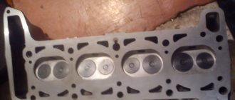
Block plane and broken gasket
A “punched” cylinder head gasket on Nivas and Shnivas is a birth defect. At some point they just went en masse. There is no need to be surprised. With modifications to the engine to meet new environmental standards, the designers are pushing the fan operating temperature further and further. This gives us an element of “glow” ignition. At a mileage of 15-25 thousand, the cylinder head gasket breaks, and so on down the list. Antifreeze to oil, oil to antifreeze. What do they do in the Papuan service? They buy a Fritex metal bag, install it, and 10 thousand later the client comes back with a new one, with the same question. Or rather, with two. How long? And the classic “what should I do?” It is not the Niva cylinder head gaskets or bolts that are to blame, it is the factory quality of processing of the block plane and the cylinder head plane that is to blame. Below I publish a photo of one of the blocks. I personally changed the gasket on it twice until I found the optimal set, which I now recommend. The metal bag does not help, but rather hinders. It cannot be crimped and does not fill uneven surfaces of the block. You need a shrink gasket that will completely accept the topography of the surface and the bolts that will constantly press it. This is the reason why hardened bolts are not rolled here. For a long time, the plant installed the Yaroslavl metal package “Fritex”, and now they have switched again to shrink gaskets. In a decent production facility, it would be easier to update the machine park and equipment, but at AvtoTAZ it turned out to be easier to go back ten steps along the road of technical progress.
Torsion bolts (plastically deformable)
Part number: 21213-1003271-01-0. Name: Torx cylinder head bolt. This name (torsion bar bolts) is fundamentally incorrect, but what can you do if they are called that on all forums and in all stores. According to science, when they say torsion bar, they mean deformation from twisting. And in this case, tensile deformation. In stores, these bolts are also called cylinder head bolts for Niva Chevrolet or cylinder head bolts of a new type. I also came across the name torx or chamomile. These bolts, unlike hardened ones, provide a constant load. That is, in a very primitive way we can talk about the grommet effect, that is, about the constant force to compress the cylinder head gasket in the axial direction of the bolt. These bolts are widely used on imported engines because they avoid human factor errors. In fact, you don't need to tighten with the precision of a torque wrench. The final values are taken as angular values. I don’t really like this approach, but such things are now commonly called “assembly guarantee”.
Niva cylinder head bolts, installation
To work with bolts, a special tool is required. E16 head, which is not always included in universal tool kits, and a torque wrench. To make the process logically complete, the price list includes an E16 head (Sata or Force) and a torque wrench ( JTK) .
I won’t invent anything about the installation technology, just completely follow the factory manual.
- Submerge the bolts in a container of engine oil.
- Let it drain. Exposure for at least 30 minutes.
- Wrap and tighten according to the diagram.
Stage 1 – tightening torque (12…20) N.m [(1.2…2.0) kgf.m];
Stage 2 – tightening with torque (50…70) N.m [(5.0…7.0) kgf.m];
Stage 3 – turning the bolts by 90-110 degrees;
Stage 4 – turning the bolts 90-110 degrees.
Tightening torque of bolt 11 (at the cylinder head tail): preliminary – (14…16) N.m [(1.4…1.6) kgf.m]; final – (32…40) N.m [(3.2…4.0) kgf.m].
Let's prepare the tool
- ratchet with a set of sockets (we will need sizes from 10 to 17 mm) and an extension;
- open-end and ring wrenches with similar sizes;
- torque wrench operating in the range from 10 to 110 N/m;
- spark plug key;
- a flat screwdriver with a wide blade, a scraper (you can use a narrow construction spatula), with their help the stuck cylinder head gasket is separated;
- circlip pullers;
- desiccant, a wooden block to support valve crackers;
- crown-shaped brush, drill;
- a hammer with a rubber or polyethylene head (for seating valves);
- a syringe with a thick needle (for suctioning technical fluids from hard-to-reach cavities);
- fire extinguisher, rags, containers of different sizes;
- magnet on copper wire for removing fallen fasteners.
If you do not have an air compressor to blow out the cylinder head and other parts of the engine, you can use a tightly inflated spare tire. Connect the nipple to the blow gun using a long hose and you can clear debris from the most difficult to reach niches.
The cylinder head device in a Chevrolet Niva car
The Chevrolet Niva engine traces its origins to the 1.7 liter VAZ 21213 engine . It has the same cylinder diameter of 82 mm and a piston stroke of 80 mm. The differences lie in the design of the cylinder head (cylinder head). Hydraulic compensators and a single-row chain with a hydraulic tensioner appeared. The cylinder head itself is cast from aluminum alloy and is designed to attach the gas distribution mechanism, valves, spark plugs and form an optimal combustion chamber in the cylinders. This head received the index 21214, it has been produced since 2003.
Important! The cylinder head, camshaft, tensioner mechanism in VAZ 21214 engines differ from modifications 21213 and 2121 and are not interchangeable.
The gasket between the head and the engine block performs the following functions:
- sealing of engine cooling channels;
- sealing the oil supply channel to the block head;
- creating optimal gas pressure in the combustion chambers and preventing them from escaping into the block.
To ensure reliable connection, the cylinder head gasket is made of a composite with a metal base or all-metal. The mating surfaces must be smooth, without scratches or cavities; surface curvature of no more than 0.1 mm is allowed.
Causes of cylinder head gasket failure
A crack or burnout of the gasket is a fairly common occurrence on the Niva Chevrolet . The vehicle is operated in extreme conditions; the engine runs at high speeds or with poor cooling off-road. The temperature in the combustion chambers reaches 1000°C, so the appearance of the slightest crack leads to rapid burnout of the gasket in this place.
A damaged node can be easily identified by the following symptoms:
- white steam from the exhaust pipe of the car (antifreeze enters the cylinders);
- drop in coolant level in the expansion tank;
- bubbling of antifreeze in the expansion tank;
- the appearance of an emulsion on the oil dipstick and timing components under the valve cover;
- increase in oil level due to antifreeze entering the crankcase;
- oil leaks from under the gasket outside the engine;
- the engine begins to stall and run intermittently;
- low compression in the cylinders.
Attention! The main reason for cylinder head gasket burnout is severe overheating of the engine, which leads to bending of the light-alloy cylinder head and the formation of cracks between the cylinder block.
The manufacturer does not regulate gasket replacement on a Chevrolet Niva . It is designed for the entire service life of the engine - 125 thousand km. This part is disposable and is replaced with a new one every time the cylinder head is removed. Dismantling the engine head may be necessary to repair valves and their seats, replace pistons and piston rings.
Features of the camshaft on a NIVA car
At first glance, the camshaft of a NIVA car is very similar to any other camshaft, however, there are some points by which you can easily determine that this part is specifically for the NIVA.
- Most camshafts have a hex key (usually 27) between the cams of the second cylinder. The camshafts that are manufactured for the NIVA car have two hexagons on their axis (between the cams of the second and third cylinders). Visually, this is the main distinguishing feature of this part.
- The next differentiating factor is the distance between the base and the top of the cam. If you need to make sure that the part is specifically for NIVA, and the presence of a second hexagon does not guarantee the authenticity of the product, pick up a caliper and start measuring. The basic camshaft cam size is the same in most cases and is 30 millimeters. But the distance from the base to the top of the Niva is 37 millimeters. Measuring any other camshaft, the distance will be no more than 36.3 millimeters.
If both of these points are met, rest assured that the spare part is genuine and you can begin installing the camshaft on your Niva.
Technical features
Due to the increased size of the cams, as already described above, the intake phase increases. When compared with other cars, on a NIVA car this phase turns out to be 20 degrees higher (which is also indicated in the passport), this allows you to easily start even at idle.
Step-by-step instructions for replacing the cylinder head gasket
The design features of the Niva Chevrolet car make it possible to remove the cylinder head without good access from below . However, the presence of an inspection hole or lift greatly facilitates access to some nuts and the coolant drain valve. There is no need to remove the engine, but it is advisable to clear the space under the hood of interfering hoses and wires.
The following tools will be needed for repairs::
- set of keys and socket heads;
- powerful wrench, ratchets, extensions;
- hammer;
- flat screwdriver;
- head or special wrench 38 for cranking the crankshaft;
- torque wrench;
- brake pipe wrench (suitable for oil line).
Advice. In addition to standard tools, wire for securing removed parts, rags, white spirit or solvent for cleaning surfaces may be useful.
Conventionally, all work on replacing the cylinder head gasket on a Niva can be divided into 2 stages : removing all attachments and all electrical sensors from the cylinder head, removing the timing mechanism and attaching the head to the cylinder block.
Procedure for removing the cylinder head of a Chevy Niva
The work algorithm is as follows:
- Drain the antifreeze from the radiator and engine block . To do this, unscrew the plug on the block with a 13 key. In this case, there is no need to drain the oil from the crankcase. Remove the terminal from the battery. We move the gearbox to neutral position.
- While the coolant is draining, we begin to disassemble the engine from the hood side . We unscrew the throttle valve, remove the throttle cable, remove the wires from the spark plugs, disconnect the electrical connectors of the injectors, TPS, IAC, oil pressure and coolant temperature sensor.
- Now you can disconnect all the cooling system hoses going to the thermostat, heater core and throttle body heating. Remove the brake booster hose from the intake manifold.
- We take the engine wiring harness and all removed hoses to the side and secure them if necessary.
- We unscrew the exhaust manifold protective screen , loosen the 4 nuts securing the exhaust pipe to the exhaust manifold. For the convenience of further actions, the exhaust pipe can be removed from the lower mounts and completely lowered under the car.
- On a Chevy Niva with power steering, the pump mounting bracket will interfere with us. It is not necessary to remove it completely - just unscrew the fastening bolts and carefully hang it on the wire.
- Now you can start opening the engine . Remove the valve cover. Using a special wrench, unscrew the oil line to the hydraulic compensators and chain tensioner.
- Set the piston of the first cylinder to TDC until the marks align by turning the crankshaft. Loosen the chain tensioner and unscrew the top sprocket. We immediately fix it in this position with wire to prevent the circuit from jumping and phase failure.
- Unscrew the 10 nuts securing the camshaft housing with bearings. You need to unscrew evenly around the entire perimeter (according to the tightening order in the instructions). Remove the assembly from the engine.
- Access to 10 cylinder head mounting bolts is now . You need to tear them off with a wrench, starting from the middle and moving to the outer bolts. The bolts are removed from their places and checked for thread condition and possible elongation (no more than 117 mm).
- Gently tapping and prying from below with a screwdriver, pull the cylinder head out of its place. After which you can remove it from the engine along with the collectors. The mass of this unit allows you to perform the operation yourself.
Advice. The camshaft and engine head mounting bolts are tightened to a sufficiently large torque to avoid accidental damage; only socket heads should be used. The fit on the bolt head should be tight without any play.
After removing the old gasket, possible damage and wear of the surfaces are assessed . If no repairs are required, the valves do not have carbon deposits, and all dimensions are within tolerance, then you can immediately begin replacing the cylinder head gasket and assembling the engine.
Assembly procedure and tightening torque of the Chevrolet Niva cylinder head
The surface of the cylinder block and cylinder head is thoroughly cleaned of old contaminants and degreased. Sharp objects cannot be used for this operation, otherwise there is a risk of leaving a scratch on a smooth surface. The new gasket is installed in its place and pressed against the top by the cylinder head. At this stage, it is important not to damage the gasket and accurately align all the channels inside.
It is allowed to use old cylinder head bolts if they have not stretched out or lost their shape. They are first lubricated with clean engine oil and allowed to drain a little. Each bolt is lowered into place and screwed into the body by hand. Now the most important operation awaits - to maintain the required tightening torque of the Niva Chevy cylinder head bolts (similar to VAZ 21213). The further performance of the engine and its service life depend on this.
Work is carried out only with a torque wrench in the following order:
- tighten with a force of 20 Nm according to the standard pattern (from the middle to the edges);
- tighten in the same order, but with a force of 70-85 Nm;
- turn each bolt 90 degrees;
- Once again tighten each bolt 90 degrees.
Important! The total tightening torque should not exceed 110-115 Nm, otherwise deformation of the bolts or cylinder head may occur.
Completion of repairs to replace the cylinder head gasket
We carry out the rest of the assembly in reverse order . We observe the tightening torques for the hydraulic compensator (20 Nm), camshaft sprocket (40-50 Nm), camshaft housing (23 Nm). We set the timing timing, make several engine revolutions and check that the marks are correct. We connect the wires, hoses, fill in coolant and test run the engine. The oil pressure lamp should definitely go out soon after starting, and there should be no engine errors.
Removing the cylinder head - work order
Before servicing, make sure that the hood lid stops are secure, put the car on the handbrake and block the wheels with shoes.
- disconnect the battery and relieve pressure in the fuel rail;
- unscrew the cap of the radiator expansion tank and drain the antifreeze;
- Carefully unscrew the throttle block mounting bolts, having first disconnected the throttle cable. We dismantle the unit as an assembly if it does not require maintenance. If the gasket is intact, it is not necessary to change it.