What is it needed for?
Engines do not actually draw fuel from the carburetor. They all have a diffuser, which is a narrowing of the air neck. When air passes through this constriction, a drop in pressure (rarefaction) occurs there. A small hole is installed in this place to supply fuel. Atmospheric pressure, acting on the fuel, squeezes it out of the carburetor's float chamber through this hole into the neck, from where the fuel enters the intake manifold and then into the engine cylinders.
Main details
Float chamber
The float system maintains a constant fuel level in the carburetor float chamber. It works as follows. When the fuel level drops, the float lowers, opens the needle valve and allows fuel to flow into the float chamber. By keeping the fuel level within a certain range, the air/fuel ratio in the mixture is more accurately maintained.
Air damper
The choke system allows you to start a cold engine by enriching the air-fuel mixture. The air damper cuts off the air supply to the carburetor and, accordingly, more fuel enters the engine, and the idle speed decreases. Therefore, a system for increasing idle speed is added to the throttle drive system to increase it when the engine warms up.
Idle system
The idle system provides the fuel required to operate the engine at low speeds when the main metering system is not operating. Adjustment screws allow you to change the air/fuel ratio at idle. Many mechanics believe that this adjustment changes the mixture composition throughout the entire rpm range, but this is not the case.
Acceleration pump
The accelerator pump provides injection of additional fuel when the throttle valve is opened sharply to prevent engine stalling and interruptions in its operation when accelerating the vehicle. If you look inside the carburetor neck and quickly move the throttle linkages, fuel should spray out of the accelerator pump outlets.
Transition system
The transition system provides a transition mode between idle and operation of the main dosing system. Many carburetors have passages or adapter holes near the throttle plates that supply fuel when they open when the throttle valves open.
Main dosing system
It meters the fuel supply to the engine when the car is moving at average speeds. It consists of the main fuel jets, the main distributor and the diffuser. The main fuel jet is located in the channel between the carburetor float chamber and the main sprayer. The main sprayer usually consists of a tube with small air holes. The air here mixes with the fuel to form an atomized fuel-air “fog.” The main fuel jet determines how much fuel will be mixed with a given amount of air.
Mechanics use different sizes of main fuel jets to calibrate the carburetor for different operating modes. By using larger jets the mixture is richer. Conversely, installing smaller jets leans the mixture.
Economizer
The most common are diaphragm type economizers, gauge rods, bypass jets, or economizer valve. When the vacuum in the intake manifold reaches a certain level, the valve opens, allowing additional fuel to flow to the engine.
Economizer valves are selected in accordance with the opening pressure, measured in millimeters of Hg. Art. The economizer valve can be selected according to the operating mode. Engines that typically produce low vacuum should be equipped with economizers that open at low vacuum levels. The metering rods move in and out in calibrated holes according to intake manifold vacuum. When the engine is under load and the vacuum is reduced, the rods extend from the main fuel jets to increase fuel flow.
What carburetor is installed on the ZIL-130 car engine and how is it designed?
The engine of the ZIL-130 car is equipped with a two-chamber balanced carburetor K-88AE with a falling flow of the combustible mixture. Both chambers operate in parallel in all modes and each feeds four cylinders with a combustible mixture.
The carburetor (Fig. 63) consists of a float chamber 1 with a float 2 and a needle valve 4, resting on the float lever, which is acted upon by a spring 3, trying to hold the needle valve in the closed position, which prevents the float chamber from overflowing when the car is moving on a bumpy road. Fuel is supplied to the float chamber from the fuel pump through the fuel supply fitting 5 through a strainer 6. In addition, in the upper part there is an air pipe 13 with an air damper 15 and an automatic valve 16. The air chamber communicates with the float chamber through channel 14, ensuring balancing. An air filter is installed on pipe 13.
Rice. 63 Carburetor K-88AE
In the middle part of the carburetor there are two mixing chambers 29, each of which contains a small 11 and a large 12 diffuser. An atomizer 10 is installed in the annular slot of the neck of the small diffuser, in which a full power nozzle 8 is installed. Moreover, the throughput of this nozzle is greater than the main fuel nozzle 27. The air into the atomizer passes through the air nozzle 9.
The main fuel jet 27, the full power jet 8, the air jet 9 and the diffusers 11 and 12 form the main metering system of the carburetor.
The idle system includes a jet 7, two outlets 33 and 32 and a channel connecting the nozzle to the outlets. The quality of the combustible mixture is adjusted with screws 31.
In the middle part there is an economizer ball valve 19, loaded with a spring 26, which tends to keep it closed. At given moments, the valve pusher is affected by a rod 20, a bar 21 connected to a rod 23, which is connected by an earring to a lever 28, rigidly mounted on the axis of the throttle valves 30. When the economizer valve is open, the fuel enters channel 35 of the full power jet 8. In the middle part also there is a piston 24 with a rod 22 of the accelerator pump, placed in a well, in the lower part of which an inlet ball valve 25 is installed. The well is connected through a channel to the spray nozzle 17. A discharge needle valve 18 is installed in the channel, which prevents fuel from being sucked in when the carburetor is operating at medium loads. Flange 34 attaches the carburetor to the engine intake manifold.
ADJUSTING THE AIR DAMPER. Adjusting the carburetor choke drive
Air damper adjustment
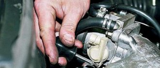
The carburetor air damper drive in the car's engine power system is adjusted if the mechanical drive rod has been replaced, or the carburetor has been removed from the car for repair or replacement. Adjustment may be required if the engine does not start well when cold, or if the air damper does not open completely after the engine warms up. Incomplete opening of the air damper leads to unstable operation of a warm engine and increased fuel consumption. Incomplete closing results in poor starting of a cold engine.
Models of carburetors that were installed on the UAZ-452
“Loaves” from the first day of their production were equipped with carburetors of the K-126, K-129 types and their modifications. This continued until 1985, when the car was completely modernized. Simultaneously with the new, more powerful engines, the UAZ-452 began to be equipped with K-131 and K-151 carburetors, as well as their numerous improved versions.
But the simplest, most reliable and repairable of them turned out to be the K-126 carburetor, which, among other things, was the most economical. If an engine with K-131 and K-151 consumed an average of 15–17 liters of gasoline per hundred kilometers, then the K-126 allowed saving 3–4 liters. All latest models of UAZ-452 carburetors are interchangeable, except that the K-126 requires an additional gasket between its “fifth” and the intake pipe.
The K-126 line is a generation of carburetors produced (Leningrad), which later became the famous “Pekar”. The first models of two-chamber K-126 were manufactured in 1964 for the new ZMZ-53 engine, which replaced the obsolete GAZ-51.
K-126G carburetors are reliable and economical
Was there an automatic choke?
Of course he was. As for domestic cars, he first used it on the Solex 21083 carburetor, but it was installed only on export VAZ 2110. The essence of its work was as follows - a special spring controlling the damper was connected to the coolant. The bimetal changed its properties as it warmed up, and, accordingly, opened or closed the damper depending on the temperature of the antifreeze.
There have also been developments for our country - this is an electronic suction control system. Instead of a cable, an electric drive was installed, and there was a programming button and a control unit in the cabin. First, the operation of the choke was programmed, and then it closed the damper based on the program. But each season had to be reprogrammed anew, because what worked in the summer, in the winter already required a different open time.
Throttle device
The throttle consists of the following elements:
- case - a metal structure that combines all elements of the mechanism;
- the valve itself is a round valve that rotates in one plane on a special axis;
- the axis is a kind of valve, a metal elongated cylinder on which the valve rotates;
- valve sensor - a device that transmits information about the position of the valve to the control unit;
- Idle speed regulator - an additional tube laid to bypass the valve, providing the cylinder group with air during idle.
The role of the throttle valve in the operation of the carburetor
The amount of fuel mixture that enters the cylinders depends on the position of the throttle valve, which, in turn, is connected to the gas pedal.
In addition, in the interior of some carburetor cars there is a special lever on the dashboard that can also be used to control the throttle. It is commonly referred to as a "choke", although technically it is a "cold start device". By pulling its handle towards himself, the driver closes the air damper, limiting the access of air and increasing the vacuum in the carburetor mixing chamber. As a result, gasoline is sucked out of the float chamber more intensively and, with a lack of air, prepares an enriched combustible mixture for the engine, which is necessary to start a cold engine.
In order for the engine to idle, the carburetor has special additional calibrated air jets, through which a strictly defined amount of air enters under the throttle valve and mixes with the fuel, even if you take your foot off the gas pedal.
How does a carburetor work?
The principle of operation of the carburetor is extremely simple. It pumps air from the atmosphere and, mixing it with gasoline, feeds it into the combustion chamber. From the school course we know that combustion is possible only in the presence of oxygen. A special air filter is used to clean the air entering the combustion chamber. Air injection is ensured throughout engine operation. Gasoline is supplied to the carburetor using a gasoline pump driven by the engine crankshaft or camshaft through a gear system.
The crankshaft speed is controlled using the accelerator drive. It is installed on the carburetor and has a connection to the gas pedal, which goes into the passenger compartment. The actuator opens or closes the valve, which increases or decreases the flow of fuel to the carburetor.
In simple words, a carburetor is a mixer that supplies air mixed with gasoline into the combustion chamber of the engine.
When is it time to clean your throttle body?
If you notice the signs described below on your car, then you need to visit a service station soon and clean the throttle.
- The idle speed began to float, the engine runs unevenly
- It's hard to start the car (especially when it's hot)
- Noticeable increase in fuel consumption
- Deterioration in dynamics (it feels like someone is holding the car from behind when accelerating)
- Jerking at the beginning of movement at low speeds
You can see the condition of the damper yourself; to do this, you need to remove the air filter pipe and look into the throttle. If you see carbon deposits on the walls, and the flap tongue is black and not golden, then there is only one conclusion that needs to be cleaned.
Setting up the float chamber
This type of work allows you to adjust the optimal amount of gasoline in the float chamber. An incorrect level causes a decrease in power, uneven engine operation, and excessive fuel consumption.
- set of wrenches;
- thin probe (diameter 1 mm);
- pliers.
1. Remove the air filter and unscrew the carburetor cover.
2. Carefully remove the float chamber cover.
3. Check the condition and position of the floats. They should be parallel to the imprints of the side walls of the float bath on the gasket.
4. If they are displaced, we align them by bringing them together or spreading them apart.
5. Next, lay the lid horizontally with the floats up and use a feeler gauge to measure the distance from the bottom of the float to the gasket. It should be equal to 1 mm. If it is higher or lower, we continue further adjustment after installing the carburetor on the engine.
6. When fuel is pumped into the float chamber, its level should coincide with the red lines, as shown in the photo.
7. If the floats are set incorrectly, this level will be lower or higher. Simple adjustment is carried out by bending or bending the tongue of the floats, then closing the carburetor cover and pumping fuel.
For details on setting up the float chamber, see here
Setting the air damper of the Solex and Ozone carburetors
In order for the engine to start confidently and continue to operate normally, it is necessary to correctly adjust the carburetor air damper mover. If the damper is incorrectly adjusted, for example, it does not completely close the air supply, a cold engine may simply not start. If the air damper does not open completely, fuel consumption increases and idle speed adjustment becomes almost impossible.
To adjust the carburetor air damper, we need two 8-mm open-end wrenches.
Checking the operation of the damper:
- First, you need to unfasten the air filter cover (so that you can see the damper);
- Then close the air damper completely (there should be no gaps between the damper and the carburetor air chamber);
- Then open the damper completely. When operating correctly, it should be in a vertical position and completely open the carburetor air chamber;
- If the air damper closes or does not open completely, it needs to be adjusted.
Adjusting the carburetor air damper drive:
- First you need to remove the air filter from the carburetor;
- Open the carburetor air damper, completely recessing the choke lever;
- Loosen the screw on the damper control lever (which clamps the cable);
- Loosen the screw that secures the suction cable casing;
- We check that the choke handle is completely recessed;
- Turn the damper adjustment handle all the way and, leaving 1 cm to the choke cable casing, clamp it;
- Then open the air damper completely, and in this position tighten the screw that holds the choke cable.
By pulling the choke handle several times, we make sure that it opens and closes completely. The air damper setting is complete.
Do-it-yourself carburetor flushing.
Washing with your own hands is quite a jewelry job. Since there are a large number of small parts. Purchase a repair kit first. Since this kit contains all the gaskets, and in some I also saw jets. Regarding the liquid in bolognese, you can also buy it. But I always washed with solvent. Of course, many are against this washing, but I’m not complaining. If you dry it well, there will definitely be no problems.
So, let's get to the point. To wash it, we need to completely disassemble it. That is, unscrew everything that is there. As a result, freeing all the channels for cleaning. We begin to wash away all the dirt and sand, thereby achieving sterility. We also use a tire inflation pump to blow out all the channels. I recommend doing this procedure on a clean and illuminated surface. As a result, after washing, it is necessary to dry the carburetor. Then assemble in reverse order. Carefully placing everything in its place.
What role does the air damper play in a carburetor?
The air damper is installed at the top of the carburetor and is a round or oval metal sheet. Its task is to limit or allow a large amount of air entering the carburetor. The principle of operation of the damper is approximately the same as that of the gas pedal. The only difference is that it works independently of the accelerator.
The air damper is used to facilitate starting an engine that has not been warmed up. That is, in the morning, when the engine is cold, part of the gasoline condenses and does not reach the combustion chamber. The other, remaining part is in too small an amount and is not enough to ignite. When the damper is closed, the volume of air entering the carburetor is limited and the amount of gasoline increases. Thus, the engine starts and the throttle opens to reduce fuel consumption and increase air volume.
To control the damper, both manual and automatic choke are used. Earlier cars used manual throttle control. A cable was attached to it and pulled into the cabin to the control handle. To close the damper, you need to pull the damper towards you until it stops. During the warming up process, it is gradually retracted to its original position and as soon as the engine begins to stably maintain idle speed with the throttle open, you can start driving.
The automatic “choke” has the simplest design and is a spring that controls the damper drive. Spring stretch directly depends on engine temperature. During the warming up process, the spring independently opens the damper and regulates the air supply level.
Classification of electric actuators of air valves
Electric drives can be divided into several main types, each of which is focused on performing specific tasks. Thus, manufacturers of electric drives today offer the following types of equipment:
By spring return
- without return spring;
- with return spring.
By management
- Two-position;
- 2- and 3-three-position;
- Modulating.
By torque
- from 2Nm to 40Nm.
By voltage
- 24V;
- 230V.
By auxiliary switches
- without additional switches;
- with additional switches.
Manufacturers focus on two main divisions of electric drives, which in all cases have fundamental differences.
Electronic damper
The last type, electronic, is being introduced into cars more and more. Its main feature is the absence of direct interaction between the accelerator pedal and the damper axis. The control mechanism in this design is already completely electric. It uses the same electric motor with a gearbox connected to the axle and controlled by the ECU. But the control unit “manages” the opening of the damper in all modes. Another sensor was additionally added to the design - the position of the accelerator pedal.
Electronic throttle elements
During operation, the control unit uses information not only from the throttle position sensors and the accelerator pedal. Signals coming from tracking devices of automatic transmissions, braking systems, climate control equipment, and cruise control are also taken into account.
All incoming information from the sensors is processed by the unit and, based on it, the optimal opening angle of the damper is established. That is, the electronic system completely controls the operation of the intake system. This made it possible to eliminate errors in mixture formation. In any mode of operation of the power plant, the exact amount of air will be supplied to the cylinders.
But this system is not without its drawbacks. Moreover, there are slightly more of them than in the other two types. The first of these is that the damper is opened by an electric motor. Any, even minor, malfunctions of the drive components lead to disruption of the unit, which affects the functioning of the engine. There is no such problem with cable control mechanisms.
The second drawback is more significant, but it mostly concerns budget cars. And it comes down to the fact that due to not very well-developed software, the throttle may work late. That is, after pressing the accelerator pedal, the ECU takes some time to collect and process information, after which it sends a signal to the electric motor of the throttle control mechanism.
The main reason for the delay from pressing the electronic gas pedal to the engine response is cheaper electronic components and unoptimized software.
Under normal conditions, this drawback is not particularly noticeable, but under certain conditions such work can lead to unpleasant consequences. For example, when starting to move on a slippery section of the road, sometimes there is a need to quickly change the engine operating mode (“play with the pedal”), that is, in such conditions a quick “response” of the engine to the driver’s actions is needed. The existing delay in throttle response can lead to complications in driving, since the driver does not “feel” the engine.
Another feature of the electronic throttle of some car models, which for many is a disadvantage, is special factory settings for the throttle operation. The ECU contains an installation that eliminates the possibility of wheel slipping at start-up. This is achieved by the fact that when starting to move, the unit does not specifically open the throttle to obtain maximum power; in fact, the ECU “strangles” the engine with the throttle. In some cases, this function has a negative effect.
On premium cars there are no problems with the “response” of the intake system due to normal software development. Also, on such cars it is often possible to set the operating mode of the power plant according to preferences. For example, in the “sport” mode, the operation of the intake system is reconfigured, and in this case the ECU no longer “strangles” the engine at the start, which allows the car to “briskly” start moving.
Spring return actuator
The equipment is designed to work in heating, air conditioning, and ventilation systems. The device primarily performs protective functions. When the air damper of the valve moves to the operating position, a spring is activated in the electric drive, which starts the action mechanism. When the current supply is stopped, the spring still returns the damper to its original position. The basic principle of operation of the return spring is that simultaneously with the rotation of the air damper to its normal position, the spring itself is activated. In the event of a power outage, the damper automatically returns to its initial (protective) position.
Actuator without return spring
This equipment is designed to work correctly with air dampers in air exchange systems. Directly in the drives of this type, the spring, when the power supply is cut off, retains its original position.
The choice of electric drive according to the type of control is of fundamental importance. Speed, convenience and efficiency - all these characteristics are of fundamental importance when it comes to choosing ventilation equipment.
- Two-position control - represents the specificity of control: turning on or off the power supply. Turning on the power supply activates the drive into operating condition. Turning off the power allows the actuator spring to freely return the choke to its standard position.
- Three-point control - with this type of control, the position of the rod does not depend in any way on the specific voltage. The actuator receives an opening or closing signal. The magnitude of the main signal is constant, but it arrives through different channels. When one contact is closed, the actuator assumes an open position (or closed); when the second contact is closed, the actuator operates exactly the opposite. If the power supply is completely absent, the drive stops. Thus, by applying a sequence of electrical pulses to the appropriate contacts, the actuator can be moved to absolutely any position.
- Analog control - with this type of control, the position of the electric drive directly depends on the magnitude of the electrical voltage in the range from 0 to 10V. So, for example, if the controller detects that a valve controlled by an electric drive should be opened halfway, then it sends a signal with a nominal value of 5 Volts. If the valve needs to be fully opened, then the control signal should be 10V. This equipment works exactly on this principle.
Having decided on the type of control, you can proceed to selecting the torque for the electric drive of the air valve. It depends on a number of factors, namely:
- The larger the total area of the air damper, the higher the drive torque must be.
- Swing-leaf valves require less torque than parallel-leaf valves.
- Equipment that is highly sealed requires more torque than dampers without enhanced sealing.
- Ventilation system pressure and specific air flow velocity additionally influence valve torque characteristics.
Important:
The position of the damper and actuator also influences the choice of torque. These factors should also be taken into account. Prefer a valve actuator with a torque rating that is greater than the required damper torque.
Diffuser capacity
The diffuser is one of the main elements of the carburetor. The defining parameters of a diffuser include its diameter. The choice of diameter strictly depends on the requirements for the engine. The numerical values of the diffuser diameter and other important parameters are initially determined based on engineering practice and experience in designing various motorcycles and engines for them. The final selection of diameter is carried out during testing on the engine. For example, small-capacity two-stroke engines used on mopeds and scooters are equipped with carburetors with a diffuser diameter of 12 to 14 mm. 125 cc sports engines use diffusers with a diameter of 36 to 40 mm. On racing engines with spool valve timing, you can find carburetors with an even larger diffuser. This trend is due to the fact that the diameter of the diffuser determines the maximum throughput of the main air channel, i.e. — maximum filling of the cylinder. The more power it is expected to develop, the larger the diffuser should be, since it will provide less resistance to the flow of the mixture.
However, the large diameter of the diffuser makes the engine less responsive, as it impairs fuel atomization in low and medium load modes. For engines operating over a wide rpm range, throttle response is more important than maximum power. In this case, carburetors with a diffuser of small cross-section are used, which improves the flow of fuel due to greater vacuum.
To increase the throughput without changing the diameter of the diffuser, special inserts are used to eliminate stepwise changes in the cross-section along the air flow path, thereby reducing parasitic turbulence.
Carburetor VAZ 2106
The VAZ “six” was produced by the Volzhsky Automobile Plant for 30 years, from 1976 to 2006. The car was equipped with carburetor engines with a volume of 1.3 liters to 1.6 liters. Various carburetors were used as part of the fuel system, but the most common was Ozone.
What is it for?
For any carburetor engine, an integral component is the carburetor, which is designed to prepare the optimal composition of the fuel-air mixture by mixing air and fuel, as well as to supply this mixture to the cylinders of the power unit. For more efficient fuel combustion, mixing with air must occur in certain proportions, usually 14.7:1 (air/gasoline). Depending on the engine operating mode, the ratio may vary.
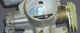
Parasitic effects
Four-stroke engine carburetors may experience a stick-close effect due to the very strong low-pressure clamping action in the intake tract. To reduce this effect, as well as prevent rapid wear leading to parasitic air leaks, the surface is coated with chrome to increase hardness and smoothness (picture below under letter a
).
The same effect forces the use of very stiff return springs to ensure the throttle valve closes. However, since spring stiffness determines the driver's throttle force, efforts should be made to minimize friction between the throttle and the housing. For example, in the picture below under the letter b
presents a chrome-plated throttle body with a return spring for a sports carburetor of the VHSD line. It can be seen that the spring used is of a very modest size, but its force is quite sufficient to close the throttle, since the chrome coating of the damper significantly reduces friction on the body.
a - chrome throttle valves, b - spring return throttle valve
We previously noted the advantages of a flat throttle valve, but it is not without its disadvantages. A flat throttle valve makes it difficult to place the idle air passage. This hole(s) is necessary to supply fuel at a time when the low idle speed hole can no longer supply the required amount of fuel and the main metering system has not yet come into operation. In the technological cycle of carburetor manufacturing, these holes are drilled after processing the main fuel well and, for proper functioning, are located slightly further than the edge of the throttle valve. With a flat choke, the holes are located very close to the atomizer, which complicates the layout. But despite this, flat choke carburetors are the most advanced in their design.
To be continued…
Purpose, main structural elements
Despite the fact that the entire system “manages” the air supply, it is structurally very simple and its main element is the throttle assembly (many people call it the throttle valve in the old fashioned way). And even this element has a simple design.
The principle of operation of the throttle valve has remained identical since the days of carburetor engines. It blocks the main air channel, due to which the amount of air supplied to the cylinders is regulated. But if this damper was previously part of the carburetor design, then in injection engines it is a completely separate unit.
In addition to the main task - air dosage for the normal functioning of the power unit in any mode, this damper is also responsible for maintaining the required crankshaft speed at idle (idle), and with different loads on the engine. It also participates in the functioning of the brake booster.
The throttle valve design is very simple. Its main structural components are:
- Frame
- Damper with axle
- Drive mechanism
Mechanical throttle assembly
Different types of throttles may also include a number of additional elements - sensors, bypass channels, heating channels, etc. We will consider the design features of throttle valves used on cars in more detail below.
A throttle valve is installed in the air duct between the filter element and the engine manifold. Access to this unit is not difficult in any way, so when carrying out maintenance work or replacement, it is not difficult to get to it and remove it from the car.
Prevent sticky suffocation
BEGINNER'S CORNER
John Gunnell
The automatic choke found on most American collector cars is a simple choke in the "throat" of the carburetor. When you close the throttle, less air enters the engine. More gas is supplied, which is what is needed for a cold start.
As the engine warms up, the choke opens, allowing the engine to breathe in more air. If the choke is stuck, the mixture will remain rich. Your warm car will be difficult to start, perform poorly and waste precious gas.
A bimetallic spring in the choke body on the carburetor is connected to the shaft on which the choke rotates. This spring compresses when cold, causing the shaft to rotate and close the valve. Because the shaft is slightly off center, the valve does not close completely.
A small hole allows just enough air to flow to create the correct starting mixture. There may also be a choke piston, controlled by manifold vacuum, that is tensioned by a spring and partially opens the choke.
The tube - or throttle body - will flow to the throttle body. When the engine reaches operating temperature, heat moves up the pipe to the bimetallic spring. As the spring heats up, it opens the choke even wider, creating a leaner mixture for better hot starts, good fuel mileage and proper performance.
Many automatic throttle bodies have rods connecting the throttle body to the throttle body. The rod controls the fast idle cam, which keeps the throttle body from closing tightly. Increasing the idle speed prevents a cold engine from stalling. As the engine warms up, the choke opens wider, the cam comes out of fast idle, and the idle speed drops.
The cam also helps start a flooded engine. There is too much gas in a flooded engine - the mixture is too rich - the throttle is closed tightly. But when you press the gas pedal all the way down, the cam forces the "unloader" mechanism to open the choke to remove excess gas from the carburetor. When the car starts, you release the pedal and the choke starts working again.
Automatic throttles seem complicated. They are designed with special bimetal spring rates, special cam designs and precise spring tension. They also require set clearances and adjustments. However, in most cases, caring for them comes down to cleaning only. It's rare that parts break or adjustments fail. Choke problems are usually caused by sticky gasoline or carbon deposits. These are maintenance items that any hobbyist can take care of with regular household tools and chemical cleaners.
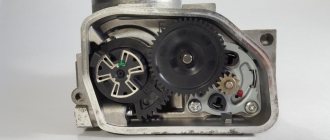
This cutaway drawing of a Carter WCD two-barrel carburetor shows some of the choke system parts that you will clean as part of your spring car maintenance.
Let's get started
Place the newspaper on a clean surface or floor. You will need a screwdriver, pliers, an adjustable crescent wrench, cleaning solvent, a parts cleaning brush, several clean rags, several clear plastic bags for storing food, index cards, and a coffee can or container to drain the oil. For personal protection, wear safety glasses , respirator and latex-free surgical gloves.
Remove the air filter. Use an adjustable wrench to loosen the clamp bolts and place them in a plastic bag. Describe or draw (take a photo?) how the clips fit together on an index card and seal it in a bag with the parts. Write #1 on this card. If your car has an oil bath air cleaner, don't tip it over or you'll end up with an oily mess.
Hold it straight and carefully set it aside for now.
Next, turn off the throttle valve. Place it in a second bag with the description of your index card #2. Use pliers to remove the tiny rod clips (place them in the third bag so you don't lose them). Disconnect the rods at their upper ends. Loosen the screws holding the choke body to the carburetor. As with other parts, place the screws in the bag with the card description.
Remove the choke housing cover and do the pouch trick again. If it has a thin metal gasket or small clock-shaped tabs, put them in the same bag. The throttle body itself can be placed on newspaper. Using a parts cleaning brush, apply solvent to the choke body. In the past, many mechanics used lacquer thinner or spray gun cleaner as a solvent. Very effective aerosol carburetor cleaners are available today. Use a coffee or tuna can to catch the solvent you wash off.
Apply solvent to all areas. Go through the cleaning procedure twice, each time using clean solvent. This will prevent contaminated fluid from forming sticky fuel deposits around the throttle shaft and exhaust piston. Move the piston by hand to force fluid out of the cylinder. Carbon deposits on the choke body are a sign that the engine is burning oil. Regular carbon deposits in the carburetor air passages can be removed with a toothpick or drill.
Since the air cleaner has been removed from the car, now is the time to clean it. In fact, if it is scratched or pitted, you can sand it down and repaint it. On an oil bath air cleaner, check the oil level. There will be a mark inside the base part indicating how high the oil level should be.
Starting with the highest numbered plastic bag, begin assembling the pieces together. By following the number sequence and following the parts descriptions you wrote on each index card, you should have no problem reinstalling the clean throttle body and inserting the parts into it correctly.
Make sure that the housing cover "catches" the bimetallic spring and moves the valve flap as the temperature changes.
Experts recommended cleaning the automatic choke housings every 5,000 miles. In the good old days, this meant about twice a year - usually in the spring and fall. Although hobbyists put fewer miles a year on their older cars, there's no excuse for not taking care of that vehicle at least every spring. By avoiding sticky throttles, you can save a lot of gas, which is more important today than when these cars were new.
data-matched-content-ui-type = "image_card_stacked" data-matched-content-rows-num = "3" data-matched-content-columns-num = "1" data-ad-format = "autorelaxed">
Nozzle design for four-stroke engines
The design described below is currently also widely used for two-stroke engines, as it allows one to obtain a leaner and more homogeneous mixture in all modes.
The body of the four-stroke type atomizer is equipped with rows of holes, and the annular chamber that surrounds it is constantly in communication with the atmosphere, but does not communicate directly with the diffuser. This allows the fuel to begin mixing with air before it reaches the diffuser, forming an emulsion inside the atomizer. With this design, the nozzle atomizer has no protruding part into the diffuser.
The operating principle of the main dosing system with a four-stroke type sprayer is shown in the figure. The holes in the lower part are immersed in fuel, since they are below its level. The holes in the upper part are always open for air to pass through. When holes in the top portion predominate, the mixture becomes leaner, while increasing the number and/or diameter of holes in the bottom portion results in increased fuel consumption with intense emulsification. Due to the location of the holes throughout the entire area of the nozzle, the annular chamber, initially filled with fuel, becomes empty as the speed increases, since the fuel is consumed through these holes, which leads to an over-enrichment of the mixture at the beginning and to its depletion in the future.
Operation of the main dosing system with a four-stroke type atomizer: Fuel rises from the float chamber along the atomizer 5, passing through the nozzle, which, together with the needle 3, regulates the fuel consumption. The fuel is initially mixed with air passing through channel 2 in the annular gap between the nozzle and the body. The emulsion is mixed with air entering through the inlet device 1 in the diffuser and mixing chamber 4.
Simply put, the location of the holes in the nozzle body and their diameter significantly affect the flow of fuel and the engine response that depends on it. Thus, by varying the parameters of the holes, it is possible to achieve the optimal mixture composition for all operating modes.