Engine repair is considered the most difficult thing in a car, because no other part contains such a huge number of interconnected elements. On the one hand, this is very convenient, because if one of them breaks down, there is no need to change the entire assembly; it is enough to simply replace the failed part; on the other hand, the more component elements, the more complex the device and the more difficult it is for those who I'm not very experienced in car repairs. However, with a strong desire, anything is possible, especially if your zeal is supported by theoretical knowledge, for example, in determining the tightening torque of the main and connecting rod bearings. If for now this phrase is a set of incomprehensible words for you, be sure to read this article before getting into the engine.
Tightening torques for classic threaded connections
Tightening torques for classic threaded connections
Repair and operation manual - Tightening torques for threaded connections VAZ-2101 - VAZ-2107
Tightening torques for threaded connections
| Detail | Thread | Tightening torque, N m (kgf m) | ||
| nominal | minimum | maximum | ||
| Engine | ||||
| Main bearing cap bolt | M10 x 1.25 | 80,36 (8,2) | 68,31 (6,97) | 84,38 (8,61) |
| Oil sump bolt | M6 | 7,8 (0,8 ) | 5,4 (0,52) | 8,23 (0,84) |
| Breather cover mounting stud | M8 | 19,6 (2,0) | 16,66 (1,7) | 20,58 (2,1) |
| Breather cover nut | M8 | 13,72 (1,4) | 8,92 (0,91) | 14,41 (1,4) |
| Cylinder head bolt: | ||||
| – pre-tightening | M12 x 1.25 | 39,2 (4,0) | 33,3 (3,4) | 41,16 (4,2) |
| – final tightening | – | 112,7 (11,5) | 95,94 (9,8 ) | 118,4 (12,1) |
| Cylinder head bolt* | M8 | 37,24 (3,8 ) | 36,67 (3,13) | 39,1 (4,0) |
| Nut securing inlet and outlet pipelines | M8 | 24,5 (2,5) | 20,87 (2,13) | 25,77 (2,6) |
| Connecting rod cap bolt nut | M9 x 1 | 50,96 (5,2) | 43,32 (4,42) | 53,51 (5,5) |
| Flywheel bolt | M10 x 1.25 | 83,3 (8,5) | 60,96 (6,22) | 87,42 (8,9) |
| Fastening bolt, chain tensioner shoe | M10 x 1.25 | 44,1 (4,5) | 36,75 (3,75) | 46,55 (4,7) |
| Camshaft bearing housing stud nut | M8 | 21,5 (2,2) | 18,33 (1,87) | 22,64 (2,3) |
| Bolt securing the camshaft sprocket and oil pump drive shaft* | M10 x 1.25 | 48,62 (4,9) | 46,1 (4,7) | 58,8 (6,0) |
| Valve adjusting bolt nut | M12 x 1.25 | 50,96 (5,2) | 43,3 (4,42) | 53,5 (5,46) |
| Valve adjusting bolt bushing | M18 x 1.5 | 98 (10) | 83,3 (8,5) | 102,9 (10.5) |
| Spark plug | M14 x 1.25 | 37,24 (3,8 ) | 30,67 (3,13 | 39 (4,0) |
| Coolant pump mounting bolt | M8 | 25,48 (2,6) | 21,66 (2,2) | 26,75 (2,7) |
| Cooling jacket outlet pipe mounting nut | M8 | 21,56 (2,2) | 15,97 (1,63) | 22,64 (2,3) |
| Crankshaft ratchet | M20 x 1.5 | 119,6 (12,2) | 101,33 (10,34) | 125,6 (12,8 ) |
| Generator bracket bolt | M10 x 1.25 | 51,94 (5,3) | 44,1 (4,5) | 58,31 (5,9) |
| Generator mounting bracket nut | M10 x 1.25 | 43,12 (4,4) | 28,63 (2,9) | 45,27 (4,6) |
| Nut of the bolt securing the generator to the bracket | M12 x 1.25 | 68,6 (7,0) | 58,3 (5,95) | 72 (7,35) |
| Nut securing the mounting plate to the generator | M10 x 1.25 | 43,12 (4,4) | 28,63 (2,86) | 45,27 (4,6) |
| Nut securing the support cushion to the engine bracket | M10 x 1.25 | 33,3 (3,4) | 21,6 (2,2) | 35 (3,57) |
| Nut securing the cushion to the front suspension cross member | M10 x 1.25 | 32,3 (3,3) | 27,4 (2,8 ) | 34 (3,46) |
| Nut securing the plate to the pillow | M6 | 8,8 (0,90) | 5,7 (0,58 ) | 9,2 (0,94) |
| Rear engine mount cross member fastening nut | M8 | 17,6 (1,8 ) | 15 (1,53) | 18,6 (1,9) |
| Nut securing the rear support to the gearbox | M8 | 27,4 (2,8 ) | 23,3 (2,4) | 28,8 (2,94) |
| Nut of the bolt securing the rear support to the cross member | M8 | 24,5 (2,5) | 15,9 (1,62) | 25,7 (2,62) |
| Clutch | ||||
| Clutch bolt | M8 | 29,4 (3,0) | 19,1 (1,95) | 30,9 (3,15) |
| Clutch and brake pedal mounting bolt nut | M12 x 1.25 | 19,6 (2,0) | 12,7 (1,3) | 20,6 (2,1) |
| Nuts for securing the clutch and brake master cylinders | M8 | 14,7 (1,5) | 9,8 (1,0) | 15,7 (1,6) |
| Clutch pipe nut | M12 | 29,4 (3,0) | 24,5 (2,5) | 31,4 (3,2) |
| Transmission | ||||
| Reversing light switch | M14 x 1.5 | 43,1 (4,4) | 28,4 (2,9) | 45,1 (4,6) |
| Bolts securing the clutch housing to the engine | M12 x 1.25 | 83,3 (8,5) | 53,9 (5,5) | 87,2 (8,9) |
| Nut securing the clutch housing to the gearbox | M10 x 1.25 | 49 (5,0) | 31,8 (3,2) | 51,4 (5,2) |
| Nut securing the clutch housing to the gearbox | M8 | 24,5 (2,5) | 15,7 (1,6) | 25,5 (2,6) |
| Bolt securing the rod clamp cover | M8 | 24,5 (2,5) | 15,7 (1,6) | 25,5 (2,6) |
| Rear cover fastening nut | M8 | 24,5 (2,5) | 15,7 (1,6) | 25,5 (2,6) |
| Nut of the rear end of the secondary shaft | M20 x 1 | 78,4 (8,0) | 66,6 (6,8 ) | 82,3 (8,4) |
| Intermediate Shaft Bearing Clamp Washer Bolt | M12 x 1.25 | 93,1 (9,5) | 79,4 (8,1) | 98 (10) |
| Bolt securing the fork to the gearshift rod | M6 | 17,6 (1,8 ) | 11,7 (1,2) | 18,6 (1,9) |
| Cardan transmission | ||||
| Front propeller shaft fork nut | M16 x 1.5 | 93,1 (9,5) | 79,4 (8,1) | 98 (10) |
| Nuts of bolts securing the elastic coupling | M12 x 1.25 | 67,6 (6,9) | 57,8 (5,9) | 71,5 (7,3) |
| Nut of the bolt securing the propeller shaft flange to the gearbox flange | M8 | 32,3 (3,3) | 27,4 (2,8 ) | 34,3 (3,5) |
| Rear axle | ||||
| Gearbox mounting bolt | M8 x 1.25 | 41,2 (4,2) | 35 (3,6) | 43,2 (4,4) |
| Differential bearing cover bolt | M10 x 1.25 | 51 (5,2) | 43,3 (4,42) | 53,5 (5,46) |
| Driven gear bolt | M10 x 1.25 | 98 (10) | 83,3 (8,5) | 102,9 (10,5) |
| Nut securing the flange to the drive gear | M16 x 1.5 | See drive gear installation and adjustment | ||
| Rear brake pad adjustment eccentric nut | M10 x 1.25 | 49 (5,0) | 41,6 (4,25) | 51,4 (5,25) |
| Steering | ||||
| Steering gear housing mounting bolt nut | M10 x 1.25 | 39,2 (4,0) | 33,3 (3,4) | 41,2 (4,2) |
| Nut of a bolt of fastening of a bracket of the pendulum arm | M10 x 1.25 | 39,2 (4) | 33,3 (3,4) | 41,2 (4,2) |
| Steering linkage ball pin nut | M13 x 1.5 | 50 (5,1)* | 42,1 (4,3) | 53 (5,4) |
| Bolt securing the steering shaft to the worm shaft | M8 | 24,5 (2,5) | 15,7 (1,6) | 25,5 (2,6) |
| Steering wheel nut | M16 x 1.5 | 49 (5) | 31,4 (3,2) | 51 (5,2) |
| Nut securing the steering shaft bracket and ignition switch | M8 | 17,6 (1,8 ) | 15 (1,53) | 18,6 (1,9) |
| Bipod fastening nut | M20 x 1.5 | 235,2 (24) | 199,9 (20,4) | 247 (25,2) |
| Pendulum arm axle nut | M14 x 1.5 | 98 (10) | 63,7 (6,5) | 102,9 (10,5) |
| Front suspension | ||||
| Bolt securing the cross member to the body side member | M12 x 1.25 | 93,1 (9,5) | 78,4 (8,0) | 98 (10) |
| Nut of the lower bolts securing the cross member to the body side member | M12 x 1.25 | 78,4 (8,0) | 66,6 (6,8 ) | 82,3 (8,4) |
| Nut of the lower arm axle mounting bolt | M12 x 1.25 | 78,4 (8 ) | 66,6 (6,8 ) | 82,3 (8,4) |
| Lower arm axle nut | M14 x 1.5 | 98 (10) | 63,7 (6,5) | 102,9 (10,5) |
| Upper arm axle nut | M14 x 1.5 | 88,2 (9,0) | 57,3 (5,8 ) | 92,1 (9,4) |
| Nut securing the upper end of the shock absorber | M10 x 1.25 | 32,3 (3,3) | 27,4 (2,8 ) | 34 (3,46) |
| Nut securing the lower end of the shock absorber | M10 x 1.25 | 58,8 (6,0) | 50 (5,1) | 61,7 (6,3) |
| Front wheel hub bearing nut | M18 x 1.5 | See checking and adjusting the front wheel alignment angles | ||
| Bolt securing the caliper to the bracket | M10 x 1.25 | 34,3 (3,5) | 29,1 (2,97) | 36 (3,67) |
| Anti-roll bar mounting nut | M8 | 17,6 (1,8 ) | 15 (1,53) | 18,6 (1,9) |
| Nut securing the ball pins to the steering knuckle | M14 x 1.5 | 98 (10) | 83,3 (8,5) | 102,9 (10,5) |
| Wheel bolt | M12 x 1.25 | 68,6 (7,0) | 58,8 (6,0) | 72, (7,35) |
| Nut of steering knuckle bolts | M10 x 1.25 | 58,8 (6,0) | 50 (5,1) | 61,7 (6,3) |
| Rear suspension | ||||
| Shock absorber mounting nuts | M12 x 1.25 | 58,8 (6,0) | 38,2 (3,9) | 61,7 (6,3) |
| Nuts of bolts for fastening transverse and longitudinal rods | M12 x 1.25 | 78,4 (8,0) | 66,6 (6,8 ) | 82,3 (8,4) |
| Brakes | ||||
| Nuts for brake drive pipeline connections | M10 | 17,6 (1,8 ) | 14,7 (1,5) | 18,6 (1,9) |
* When tightening nuts and bolts, it is allowed to round the tightening torques to tenths of kgf m within the tolerance.
Quote
Let's start to disassemble
First, drain the oil and antifreeze. We remove the protective cover, the air filter with pipes, disconnect the ignition coil connectors, the throttle cable and the throttle assembly.
We remove the thermostat housing and simultaneously disconnect all the available connectors and pipes. We remove all the wiring that was in our way towards the battery.
We remove the generator. We unscrew the eight thirteen nuts holding the intake manifold and remove it. We unscrew all the bolts securing the valve cover, as well as the side engine support.
Unscrew the eight nuts and remove the exhaust manifold.
Remove the timing belt, camshaft pulleys and pump.
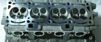
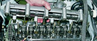
In three passes, so as not to deform the part, we first loosen and then unscrew twenty bolts of the camshaft bearing housing, the head is eight. Be sure to follow the sequence shown in the photo.
Remove the bearing housing. We remove the camshafts; there is a distinctive lip on the intake camshaft.
Also, in several passes, we first loosen and then unscrew the ten cylinder head mounting bolts. Be sure to follow the sequence shown in the photo.
Remove the cylinder head. All sixteen valves are replaced.
Let's move on to the cylinder block
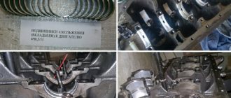
We remove the pallet. Rotating the crankshaft as it is convenient for us, unscrew two bolts on each connecting rod cap. We use a TORX E10 head for this.
We take out the pistons along with the connecting rods. To do this, use the wooden handle of a hammer to press the connecting rod from below and lightly tap it to knock it up. We remove the old liners and buy new ones of the same size according to the markings on them. Here is another stone in AvtoVAZ’s garden, the owner has never climbed into the car from the interior or into the engine, but three pistons were of group “B” and one was “C”. It turns out that at the factory they re-sharpened one cylinder a little and simply put an enlarged piston there, no words. There are no options, we take group “C”, don’t sharpen the engine because of this. We will not touch the main liners either.
crank mechanism
This main engine unit consists mainly of the following groups:
Each part of the group has several additional elements. For example, each piston carries a set of O-rings, a connecting pin and pin retaining clips. The crankshaft has bearings and oil seals. The most interesting thing is the structure of the connecting rods.
The principle of operation of the mechanism
VAZ engines, like other cars, are based on explosive combustion of fuel. The piston creates a certain compression of the air-gasoline mixture, a spark from the spark generator ignites it, pushing the piston down, and the crank mechanism (CPM) converts translational motion into rotational motion. This occurs due to the special shape of the crankshaft. The mounting points of the connecting rods are located so that while the connecting rods pushing the pistons rise, the connecting rods pushed by the piston are lowered. And this process takes place in shifts.
Set of connecting rods "Priors"
These parts are collapsible. The main part is made of high quality metal. Only in the upper ring, where the piston locking pin fits, is an insert made of a different metal installed. In general, the connecting rod consists of the following parts:
- connecting rod;
- liner covers;
- coupling bolts 2 pcs.;
- special washers;
- connecting rod bearing.
This is due to the fact that the liners have special grooves for the passage of engine oil. Due to the high rotation speed, this unit requires uniform and abundant lubrication. The slightest discrepancy between these grooves and the oil supply holes of the crankshaft will lead to a disruption in the flow of lubricant and, as a result, jamming of the engine.
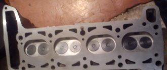
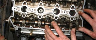
Cylinder head repair
We mark all hydraulic compensators with numbers using an ordinary clerical touch and put them away. An ordinary magnet will help you pull them out. We dry out the valves and remove the oil seals (valve seals), the valves into scrap metal, the oil seals into the trash. We clean all channels. We take the head for grinding, just in case. After washing it again with kerosene after sanding and blowing it with air, we begin to assemble it.
We arrange the freshly purchased valves in the sequence in which they will stand in the cylinder head and begin to grind in one by one. Lubricate the valve stem with clean oil and apply lapping paste to the edge.
We insert the valve into place and put a valve grinding tool on the valve stem. The stores sell a device for manual lapping, but since this is the twenty-first century, we are mechanizing the process. We take the old valve and cut off the rod from it, select a rubber tube for it of such a diameter that it fits tightly. The rod is in a reversible drill, one end of the tube is on it, the other is on the valve being ground in. At low speeds we begin to grind the valve, constantly change the direction of rotation and periodically press it to the seat or weaken the force. On average, the valve takes about twenty seconds. We take it out and wipe it. The valve is considered ground in if a uniform gray strip of at least 1.5 mm wide appears on the chamfer.
The same stripe should appear on the valve seat.
Video of manually grinding valves
For a sixteen valve head, everything is the same, only there are twice as many valves. After lapping, all valves and seats are thoroughly wiped and washed with kerosene to remove any remaining lapping paste. We check for leaks. We tighten the old spark plugs and put all the valves in place. Pour kerosene and wait three minutes, if the kerosene does not run away all is well, otherwise we grind the valves on this cylinder.
We had to grind four valves again, after which the kerosene stopped flowing.
We stuff new valve seals.
We put the valves in place and dry them. Before doing this, lubricate the valve stems with clean oil. After lubricating it with clean oil, we put the hydraulic compensators in place and, covering them with a clean cloth, remove the head out of sight. We're done with the cylinder head.
Priora connecting rod dimensions
By pushing the piston up to its entire length, the connecting rod strictly fixes the volume of the combustion chamber. From this we can conclude that the volume of the working cavity of the cylinder itself, in which the fuel burns, also depends on its length. That is, if the length is increased, the volume will become smaller. And if you shorten it, the size of the camera will increase accordingly. The factory engine comes with standard length connecting rods. It is 150 millimeters. It is measured from the axial point of the center of the head (pin attachment) to the same line of the lower part attached to the crankshaft. This size provides the motor with standard factory parameters. For example, engine displacement. It is 1597 cubic centimeters. Or as the owners say, the engine is “one and six”.