Dear readers and subscribers, it’s nice that you continue to study the structure of cars! And now we bring to your attention the electronic fuel injection system, the operating principle of which I will try to explain in this article.
Yes, we’ll talk about those devices that have replaced time-tested carburetor power systems from under the hoods of cars, and we’ll also find out how much modern gasoline and diesel engines have in common.
Electronic fuel injection system
Perhaps we would not have discussed this technology if a couple of decades ago humanity had not become seriously concerned about the environment, and toxic exhaust gases from cars turned out to be one of the most serious problems.
The main drawback of cars with engines equipped with carburetors was incomplete combustion of fuel, and to solve this problem, systems were needed that could regulate the amount of fuel supplied to the cylinders depending on the operating mode of the engine.
Thus, injection systems or, as they are also called, injection systems, appeared in the automotive arena. In addition to improving environmental friendliness, these technologies have improved engine efficiency and power characteristics, becoming a real boon for engineers.
Today, fuel injection is used not only on diesel, but also on gasoline units, which undoubtedly unites them.
They are also united by the fact that the main working element of these systems, no matter what type they are, is the nozzle. But due to differences in the method of fuel combustion, the designs of injection units for these two types of engines, of course, differ. Therefore, we will consider them in turn.
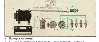
Electronic control unit
This is a microcomputer that processes data coming from sensors and controls actuators according to a certain algorithm.
The program itself is stored in a ROM chip, the English name is CHIP. The contents of the “chip” are usually divided into two functional parts - the program itself, which performs data processing and mathematical calculations, and the calibration block. Calibrations are a set (array) of fixed data (variables) for the operation of the control program.
For proper operation of the injection system, it is necessary to have working sensors and actuators.
Injection systems and gasoline
Electronic fuel injection system. Let's start with gasoline engines. In their case, injection solves the problem of creating an air-fuel mixture, which is then ignited in the cylinder by a spark from the spark plug.
Depending on how this mixture and fuel is supplied to the cylinders, injection systems can have several varieties. Injection happens:
- central;
- distributed;
- direct;
- combined.
Central injection
The main feature of the technology, located first in the list, is one single injector for the entire engine, which is located in the intake manifold. It should be noted that this type of injection system in its characteristics is not very different from a carburetor, therefore today it is considered obsolete.
Distributed injection
Distributed injection is more progressive. In this system, the fuel mixture is also formed in the intake manifold, but, unlike the previous one, each cylinder here boasts its own nozzle.
This variety allows you to experience all the advantages of injection technology, therefore it is most loved by automakers and is actively used in modern engines.
Direct injection
But, as we know, there are no limits to perfection, and in pursuit of even higher efficiency, engineers developed an electronic fuel injection system, namely a direct injection system.
Its main feature is the location of the injectors, which, in this case, extend their nozzles into the combustion chambers of the cylinders.
The formation of the air-fuel mixture, as you might already guess, occurs directly in the cylinders, which has a beneficial effect on the operating parameters of the engines, although this option is not as environmentally friendly as that of distributed injection. Another noticeable drawback of this technology is the high requirements for the quality of gasoline.
Combined injection
The most advanced in terms of the level of emissions of harmful substances is the combined system. This is, in fact, a symbiosis of direct and distributed fuel injection.
Principle of operation
Injection engine units with a single nozzle operate according to the following scheme:
- the engine starts;
- sensors read and transmit information to the control unit;
- real data are compared with reference data, the moment of opening the injector is calculated;
- a signal is transmitted to the electromagnetic coil;
- gasoline is supplied to the manifold for mixing with air;
- The fuel mixture is supplied to the cylinders.
Functioning of a unit with distributed injection:
- air is supplied to the motor;
- sensors determine volume, temperature, crankshaft performance, damper position;
- the volume of fuel for the supplied air is calculated by the control unit;
- a signal is sent to the injectors;
- they open at the programmed time.
- gasoline is mixed with air in the manifold, and the mixture is supplied to the cylinders.
How are diesels doing?
Let's move on to diesel units. Their fuel system is faced with the task of supplying fuel under very high pressure, which, when mixed in the cylinder with compressed air, ignites itself.
There are a lot of options for solving this problem - direct injection into the cylinders is used, and with an intermediate link in the form of a preliminary chamber; in addition, there are various designs of high-pressure pumps (HHP), which also adds variety.
However, modern motorists prefer two types of systems that supply diesel fuel directly to the cylinders:
- with pump injectors;
- Common Rail injection.
Pump nozzle
The pump-injector speaks for itself - in it the nozzle that injects fuel into the cylinder and the injection pump are structurally combined into one unit. The main problem with such devices is increased wear, since the pump injectors are connected by a permanent drive to the camshaft and are never disconnected from it.
Common Rail system
The Common Rail system takes a slightly different approach, making it more preferable. There is one common injection pump, which supplies diesel to the fuel rail, which distributes fuel to the cylinder injectors.
This was just a brief overview of injection systems, so, friends, follow the links in the articles, and using the Engine section, you will find all the injection systems of modern cars to study. And subscribe to the newsletter so as not to miss new publications in which you will find a lot of detailed information on car systems and mechanisms.
See you again!
Tags
engine
Injection duration and flow rate curve (injection)
The term "feed rate" describes the curve of the amount of fuel injected into the combustion chamber as a function of the crankshaft or camshaft angle (crankshaft or camshaft angles, respectively).
One of the main parameters influencing the injection intensity curve is the injection duration. It is measured in crank or cam angles or in milliseconds and is the period during which the injector is open and fuel is injected into the combustion chamber. The figure shows how the amount of fuel injected is started by the pump camshaft and how the fuel is injected from the injector ( as a function of the camshaft angle). It can be seen that the pressure characteristic and injection rate curve vary greatly between the pump element and the injector, and that they are influenced by the parts that determine the injection (cam, pump element, injection valve, fuel line (feed line) and injector).
Different diesel engine systems require different injection times in each case. Engines with direct injection require approximately 25 - 30° of crankshaft rotation at a certain number of revolutions, and engines with pre-chamber require a crankshaft rotation angle of 35 - 40°. The injection duration at a 30° crankshaft rotation corresponding to a 15° camshaft rotation means an injection duration of 1.25 milliseconds for an injection pump speed of 2000 rpm.
To keep fuel consumption and sulfur emissions low, the injection duration must be determined as a function of the operating point and depends on the start of injection. At the start of injection, only a small amount of fuel should flow, while at the end a large amount of fuel is required. The injector should then close as quickly as possible. This feed rate curve will result in a slow increase in compression pressure. The combustion will thus be “soft”. In direct injection engines, combustion noise is noticeably reduced if a small portion of the fuel injected into the combustion chamber is finely atomized before the main injection.
This injection method remains very expensive. Engines with a split combustion chamber (pre-chamber or swirl chamber) use needle throttling injectors. These injectors produce a single jet of fuel and determine the flow rate curve. The injectors control the outlet cross-section as a function of the injection valve (discharge valve) stroke.
Secondary injection (or so-called "dripping") is particularly undesirable and occurs when the injector quickly re-opens after it has closed, and it injects poorly prepared fuel later in the combustion process. This fuel does not burn completely or does not burn at all and exits through the exhaust gases as unburned hydrocarbons.
Quick-closing nozzles prevent this “dripping.” The "dead volume" at the bottom of the injector seat produces an effect similar to "dripping". Fuel vapors accumulated in this volume exit into the combustion chamber after combustion is completed and also enter the exhaust gases, where they increase emissions of unburned hydrocarbons. The smallest “dead volume” is obtained with injectors with a seat with holes.
Story
The first manifold injection system was developed by Johannes Spiel at the Hallesche Maschinenfabrik.[15] Deutz began mass production of stationary four-stroke engines with manifold injection in 1898. Grade built the first two-stroke engine with manifold injection in 1906; The first production four-stroke manifold injection aircraft engines were built by Wright and Antoinette that same year (Antoinette 8B).[16] In 1912, Bosch equipped a jet ski with a homemade fuel injection pump built from an oil pump, but this system turned out to be unreliable. In the 1920s, they tried to use a diesel fuel injection pump in a gasoline-powered Otto engine. However, they failed. In 1930, Moto Guzzi built the first manifold-injected Otto engine for motorcycles, which eventually became the first manifold-injected land vehicle engine.[17] From the 1930s to the 1950s, manifold injection systems were not used in passenger cars, although such systems existed. This happened because the carburetor turned out to be simpler and less expensive, but at the same time a sufficient mixture formation system that did not yet require replacement.[13]
In approx. 1950, Daimler-Benz began developing a gasoline direct injection system for its Mercedes-Benz sports cars. However, for passenger cars, a manifold injection system was found to be more appropriate.[13] Eventually, Mercedes-Benz W 128, W 113, W 189, and W 112 passenger cars were equipped with Otto injection engines.[18][19]
From 1951 to 1956, FAG Kugelfischer Georg Schäfer & Co. developed the Kugelfischer mechanical injection system.[17] It was used in many passenger cars such as the Peugeot 404 (1962), Lancia Flavia iniezione (1965), BMW E10 (1969), Ford Capri RS 2600 (1970), BMW E12 (1973), BMW E20 (1973), and BMW E26 (1978).[20]
In 1957, Bendix Corporation introduced the Bendix Electric, one of the first electronically controlled manifold injection systems.[21] Bosch built this system under license and marketed it as the Bosch D-Jetronic from 1967.[20] In 1973, Bosch introduced its first proprietary multipoint injection system - electronic Bosch L-Jetronic, and mechanical, non-drive Bosch K-Jetronic.[22] Their all-digital Bosch Motronic system was introduced in 1979. It is widely used in German luxury salons. At the same time, most American automobile manufacturers stuck to electronic single-point injection systems.[23] In the mid-1980s, Bosch upgraded its non-Motronic multipoint injection systems with digital engine control units, creating the KE-Jetronic and LH-Jetronic.[22] Volkswagen developed the digital Volkswagen Digijet injection system, which evolved into the Volkswagen Digifant system in 1985.[24]
Inexpensive single-point injection systems that operated with two-way or three-way catalysts, such as the Bosch Mono-Jetronic introduced in 1987,[22] allowed automobile manufacturers to offer an economical alternative to carburetors even in their economy cars, which contributed to the widespread adoption of injection systems with manifolds in all segments of the passenger car market during the 1990s.[25] In 1995, Mitsubishi introduced the first Otto direct injection gasoline engine for passenger cars, and since then, gasoline direct injection has replaced manifold injection, but not in all market segments; Some recently produced passenger car engines still use multipoint injection.[26]
Content
- 1 Description 1.1 Main types 1.1.1 Single point injection
- 1.1.2 Multipoint injection
- 1.2.1 Mechanical control
- 1.4.1 Simultaneous injection
Phased spray on 797
Temur
Expert
- 09.07.2007
- #1
- 09.07.2007
hor-sheff
Expert
I made a mistake! I thought it would work with 797!
Truly an Oak block!
Kuzmin_M
Specialist
- 10.07.2007
If you pull the DF, it will naturally go over!
And so in the firmware in the configuration moisture, remove the DF and you will be happy.
No, with 797 It doesn’t work, this tricky thing doesn’t have configuration flags.
And mind you, without a DF, the car starts worse, that is, you have to oil the starter longer (in the first strokes, the block determines the working cylinder from a pair of synchronous ones), and after starting, pay attention to the injection time; strangely enough, the injection remains phased even without a DF: 13: how it is calculated is not clear :13: probably according to the KDP.
I myself am looking for such firmware, without DF at 1.5 8V STP-6 does not drive it, a lot of things have appeared on the DC, but there are none on the DF.
Guest
- 10.07.2007
If you pull the DF, it will naturally go over!
And so in the firmware in the configuration moisture, remove the DF and you will be happy.
Temur
Expert
- 10.07.2007
No, with 797 It doesn’t work, this tricky thing doesn’t have configuration flags.
And mind you, without a DF, the car starts worse, that is, you have to oil the starter longer (in the first strokes, the block determines the working cylinder from a pair of synchronous ones), and after starting, pay attention to the injection time; strangely enough, the injection remains phased even without a DF: 13: how it is calculated is not clear :13: probably according to the KDP.
I myself am looking for such firmware, without DF at 1.5 8V STP-6 does not drive it, a lot of things have appeared on the DC, but there are none on the DF.
Kuzmin_M
Specialist
- 10.07.2007
In fact, it turns out phased, only without DF, it is calculated only according to DPKV.
At the initial moment (start moment), the working cylinder is determined from a pair of synchronous ones, either 1-4 or 3-2, and then after a stroke of 1-3-4-2, it turns out to be phased, but by what algorithm this is calculated, I still don’t understand myself .
It seems that at the initial moment simultaneous injection works, then the working cylinder is somehow calculated based on the acceleration of the CV, but I do not confirm the correctness of my theory, I have not checked it (I have not climbed with an ascillograph).
It is possible that the initial injection of papro is parallel - this is more like it. It appears after the first full turn of the HF carrying the DF signal.
That is, during two revolutions of the HF there was not a single pulse from the DF, the unit was switched on not in a phased mode but in some other mode, either simultaneous or pairwise parallel, and the first two working cylinders were calculated, from which the countdown proceeds further.
Types of power systems
There are the following types of engine power systems, differing in the place of formation of the mixture:
- inside engine cylinders;
- outside the engine cylinders.
When a mixture forms outside the cylinder, the fuel system of a car is divided into:
- fuel system with carburetor
- using one injector (with mono injection)
- injection
Purpose and composition of the fuel mixture
For smooth operation of a car engine, a certain fuel mixture is required. It consists of air and fuel mixed in a certain proportion. Each of these mixtures is characterized by the amount of air per unit of fuel (gasoline).
An enriched mixture is characterized by the presence of 13-15 parts of air per part of the fuel. This mixture is fed at medium loads.
A rich mixture contains less than 13 parts air. Used for heavy loads. Increased gasoline consumption is observed.
A normal mixture is characterized by the presence of 15 parts air to part fuel. The lean mixture contains 15-17 parts of air and is used at medium loads. Economical fuel consumption is ensured. A lean mixture contains more than 17 parts air.
Multipoint injection adjustment
Before considering the principle of injection adjustment, it is worth considering that each modification of the vehicle has its own subtleties of operation. Therefore, setting up the system can occur in different ways. Here's how the procedure is performed for the most common modifications.
Bosch L3.1, MP3.1
Before you start setting up such a system, you need to:
- Check the ignition condition. If necessary, worn parts are replaced with new ones;
- Make sure the throttle is working properly;
- A clean air filter is installed;
- The engine warms up (until the fan turns on).
First, the idle speed is adjusted. For this purpose, there is a special adjusting screw on the throttle. If you turn it clockwise (twists), then the XX speed indicator will decrease. Otherwise, increase.
In accordance with the manufacturer's recommendations, exhaust quality analyzers are installed on the system. Next, remove the plug from the air supply adjusting screw. By turning this element, the composition of the VTS is adjusted, which will be indicated by the exhaust gas analyzer.
Bosch ML4.1
In this case, the idle speed is not set. Instead, the device mentioned in the previous review is connected to the system. The operation of multi-point spraying is adjusted based on the state of the exhaust gases using an adjusting screw. When the hand turns the screw clockwise, the CO composition will increase. When turning in the other direction, this indicator decreases.
Bosch LU 2-Jetronic
Such a system is adjusted to the XX speed in the same way as the first modification. The mixture enrichment is adjusted using algorithms programmed into the microprocessor of the control unit. This parameter is adjusted in accordance with the pulses of the lambda probe (read more about the device and its operating principle separately).
Bosch Motronic M1.3
The idle speed in such a system is regulated only if the gas distribution mechanism has 8 valves (4 for intake, 4 for exhaust). In 16-valve engines, XX is adjusted by an electronic control unit.
The 8-valve valve is adjusted according to the same scheme as previous modifications:
- XX is adjusted with a screw on the throttle;
- A CO analyzer is connected;
- Using the adjusting screw, the composition of the military technical equipment is adjusted.