For ease of use of vehicles, car manufacturers have long used central locking, which is a subsystem of a larger “comfort” system and is often combined with an alarm system. Central locking – locks one or all car doors. In addition, it is responsible for unlocking the fuel tank flap and trunk. If the car model is old, then the system can be installed additionally. Has remote control (RC).
How it works
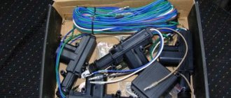
The car central locking system includes:
- Input sensor: limit switches and microswitches.
- Block – central locking control.
- Actuators.
Input sensors include:
- Door limit switches – are responsible for the location of car doors, transmitting a signal to the power supply.
- Microswitches are responsible for the structural elements of the locking device.
Microswitch functions:
- Two microswitches fix the cam mechanism of the front doors: one is responsible for the “lock” signal, and the other is “unlock”.
- Two more are responsible for the central locking.
- Microswitch for the lever mechanism of the lock drive.
Such a device involves transmitting a signal from microswitches first to the control unit, then to the power circuit, through which the signal goes to the doors (actuators), trunk lid and fuel tank flap. Result: the locks open.
An actuator is an actuator that causes the lock to operate.
Comprises:
- Electric motor.
- GEARBOX.
The system operates remotely (remote control): There is a special remote control button on the ignition key, the signal is transmitted to the antenna, and from it to the unit. The range of the remote control is 10 meters. You can connect to an alarm system.
Installation instructions
Installation of the device is carried out as follows:
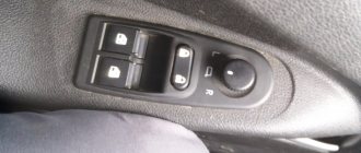
- First, the plastic door trim is removed and a location for installing the unit is selected. When choosing a location, it is necessary to take into account the location of the window lifter elements. According to many experts, it is better to install the system in the lower left corner of the door.
- The next step is to install the lock activators, each of which is mounted separately on each door. It is necessary to drill the corresponding holes in the structure in advance and secure them with self-tapping screws. After this, the activator must be connected to the rod. Next, the activators need to install clamps on the manual control elements of the central locking.
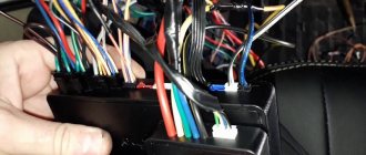
- The wiring is being laid - All wires must be securely fixed; plastic clamps can be used for this. They should not be placed at the bottom of the door, since moisture usually collects in this place, so it is better to choose a place between the door and the body, installing a rubber tube here in advance. Thanks to it, the wiring can be protected from damage.
- The next step will be to dismantle the control panel. Having done this, the old wiring from the window regulators can be removed and a new one can be laid, which is subsequently connected to the drive.
- After this, the activator drives are connected. When all these steps are completed, the wiring must be pushed under the control panel on one side, and into the glove box on the other side. A pass-through pipe is mounted into the rack; a screwdriver may be required to install it.
- Now a fuse is connected to the connector and this circuit is connected to the central locking power supply, the entire structure is installed under the center console. The cable from the central locking system must be connected to the on-board network, plus to the fuse, minus to the body. Assembly is carried out in reverse order.
Loading …
Control block
The block is responsible for the operation of the lock. The control circuit includes digital elements - they transmit a signal to the rest of the system components.
This device of the car central locking system interacts with the alarm system and can also be controlled by a remote control. You can install it yourself, but most modern cars already have central locking with remote control.
The remote control operates from a separate electronic unit, which is connected to the system and controls it.
Connecting an alarm to the central locking system with a negative and positive pulse
In this case, when a minus is applied to a pair of lock wires, they close or open. Finding such wires is relatively easy using a probe (lamp). You should alternately close the wiring that comes out of the car doors on the driver’s side. As soon as the right pair of wires is found (the door opens or closes), the problem can be considered solved.
In those cases where it was not possible to find the wires, you will have to “dig” into the central locking unit. You will need to find a special relay in it that is responsible for closing/opening the doors, and then solder the security system wiring into it.
Working with a lock controlled by a “plus” pulse is similar to the scheme described above. Only the required pair of wires in this case, as you yourself understand, will have a plus polarity. In other words, positive wires should come from the alarm.
The connection diagrams for the voiced types of central locking with a built-in relay will therefore be as follows:
- “Negative” pulse: NC (normally closed) contacts are not needed, NR (normally open) contacts are connected to the “minus”, common contacts go to the control wires.
- “Positive” impulse: open contacts are connected to positive, closed contacts are not used, common ones, as in the previous version, are connected to the found control wiring.
Central locking functions
The advantage of a central locking device with remote control in a car:
- Save time. Instead of closing each door in turn, you need to close one - the rest are locked automatically.
- Versatility. The device is standard. There is no need to select a model.
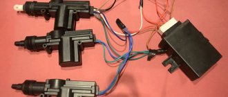
A standard car lock kit consists of:
- Electric drive (five-wire).
- Central locking.
- Two-wire electric drives.
- Control controller.
The system is operated by a key or remote control.
Functional features:
- The system works with any type of alarm system.
- The remote control start button is placed on the key fob for convenience.
- If your car has an alarm system and a remote control, there is no point in ordering another one - it’s better to save money.
- In addition to the doors and hatch, you can also connect the trunk of the car. It can also be controlled by remote control.
- An important feature is the recoding of safety capabilities. For example, if the speed is exceeded, the doors are automatically locked. Or set the opening sequence: first the driver's side door, and when pressed again, the rest.
DIY car tinting at home: simple technology
There are two control methods in total.
- Mechanical. To do this, use a regular key inserted into the lock of the main driver's door. The rest of the doors are already closing or opening from him.
- Remote. Works via key fob. It is good because it is programmable and can be adjusted to the driver’s requirements.
It also happens that the central locking system does not work at a long distance. Therefore, it is better to press the button in the immediate vicinity of the car and make sure that all doors are locked. If the lock does not work, then you cannot leave the car unattended. Go straight to service.
Device Features
Many car owners have a compressor for their car, a set of spare relays for repairs, or an alarm system. In principle, all this is useful and necessary.
So I consider central locking an extremely useful invention, which is now widely used on cars. Its diagram is not the simplest, so you may have difficulties with how to connect the lock with your own hands.
If you are planning to buy a new car or decide to buy the central locking system itself for installation on an old car, the decision will be correct. It's not that expensive to buy. How much a central locking kit costs depends largely on the manufacturer and the features available. I advise you to take high-quality and reliable ones, even if the price is steep.
How to care for your central locking
Central locking in a car is a set of systems that provide additional convenience and safety, but it requires additional care. Problems with car locks usually arise in winter: after washing, if the locks are not properly ventilated, moisture freezes in them and grabs the rods.
To prevent this from happening, the car must be kept with the engine running, periodically forcing the locks to work, for about an hour. Or just drive around the city until the car dries out.
More information about the device and connecting the central locking in the video:
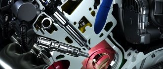
Problems in the operation of the activator electric drive
The central locking actuator is quite fragile and does not tolerate overload. The activator body, made of plastic, can easily melt if the frequency of door closing is excessively high. The duration of the control pulse also plays an equally important role. Try to always remember about the extreme fragility of the activator and not to load it during operation.
We recommend: Electrolyte for batteries
It is easy to guess that the activator is located in each individual door of the car. If the body of one of them melts due to overheating of the electric drive commutator, this becomes the cause of many problems:
- the activator on individual doors stops functioning;
- Constant overloads in a jammed electric drive cause the fuse to fail.
The actuator mechanism is entirely made of plastic. Gears can easily wear out and break during operation, or melt when the commutator overheats. As a result, when the central locking operates, characteristic creaking sounds are heard - a sure sign of imminent failure of the activators. Likewise, if the gearbox of the mechanism is humming, but the doors do not open or close.
Malfunctions of this kind can also be associated with all sorts of defects in the gearmotor and its traction. If you have recently replaced your central locking system, the reason may be that it was installed incorrectly. The mechanism may also be incorrectly adjusted or the fastening may be damaged. In any case, the door trim should be removed and checked visually.
Rear door glass
In the rear door window, due to the impossibility of completely lowering the glass due to the arched projection of the door above the wheel, the sliding glass is narrowed, and the additional glass, which is made fixed, is enclosed along the contour in a rubber seal.
Rice. Door seal: a - section along the top of the door window; b - cross-section along the B-pillar through the windows of the front and rear doors; c - cross-section along the door threshold; 1 - edge of the facing lining; 2 — external seal; 3 — arch of the headliner; 4 — internal seal; 5 — sliding glass; 6 - groove; 7 — door frame; 8 — threshold facing; 9 - outer door panel
Connection of the “signaling” depending on the type of central locking
Depending on the type of lock product, the installation and connection of the security system will proceed differently. Before performing the connection procedure, you need to find the signal circuits.
To do this, you need to understand the types of control modules for central locking:
- Block with negative polarity. When you close one of the signal contacts to ground, the locking devices will automatically close. They are opened by closing the second contact to ground.
- The module is controlled via positive polarity. In this case, the procedure for opening and closing doors is similar. Only +12 volts is supplied to each of the contacts.
- The module can work with an alternating signal. One output of the device is connected to the ground to the body, and the other receives 12 volt voltage. This leads to the unlocking of the locking devices. When the polarity changes, the devices are closed. If voltage is supplied to the contacts separately, this will not affect the functioning of the devices in any way.
For the first case, you can find a way out using a control light. The light indicator is connected to the ground of the car, that is, its body, after which each output is diagnosed separately. If it is necessary to find a positive output, then the test lamp is connected to the positive contact.
Central locking with negative polarity
Scheme for connecting central locking with negative potential
The outputs of the security system used for central locking are divided into power and signal. If we are talking about a device with negative polarity, then relays will be used for connection. This refers to elements with which you can unlock and close lock products.
You can connect the alarm to the central locking in accordance with the diagram below:
- The green contact is connected to the connector of the security complex. It is used to close door locks.
- The white output also goes to the “signaling” block, intended for opening locks.
In accordance with the diagram, the upper node of the system is made in the form of a closing relay. Open contact components are connected to ground, the car body. And the general outputs must be connected to the signal contacts of the locking device. Please note that there is no need to cut the cables from the processor module plug; you need to connect the outputs to them, which we described above.
In some models of security systems, low-current signal channels are used as outputs rather than relay contact components.
Central locking with positive polarity
The connection diagram will look identical. Only normally open contact elements should be connected not to the car body, but to the positive terminal. The upper relay is a locking relay, and the lower device is designed to open door locks. Signal contacts can be used instead of these components. But with such a scheme, the diode elements must point to the lock plug.
Central locking with polarity reversal
Scheme for connecting central locking with reverse polarity
The locking device that operates with alternating potential is the most difficult to connect. The central locking processor must include a relay in its circuit. Two contact elements connected from the lock module plug to the actuators must be connected to the “signal” plug. We are talking about contacts located in the middle
When performing this task, it is important not to mix up the wires. When the upper relay is activated, the locks should close, and not vice versa
Main features of this scheme:
- When the central locking is unlocked, contact number 1 receives a positive pulse, and component number 2 receives a negative pulse.
- When forced to open, the circuit changes. The first output is grounded, and the second contact receives a positive pulse.
- After connecting the components in accordance with the diagram, the contacts under the first and second numbers do not contact the plug of the control processor of the central lock. This point can be called a disadvantage, since the car owner will have to interfere with the standard wiring and break the connection.
Controlling the locking device using the reverse polarity method is more relevant on cars made in the USA, and not on all models. But security systems that are equipped not with relays, but with control devices, are not manufactured today.
Door fastening
Each door at the front end is suspended from the body on two hinges. The cheek 1 of each hinge, adjacent to the body pillar b, is secured with screws 4 screwed into a plate 5 held inside the pillar by a holder 3. The dimensions of the holder allow the plate to be moved during adjustment. The hinge cheek 10, adjacent to the door, is attached to it with bolts 8, which pass through the holes in the door reinforcement V and are screwed into the threaded holes of this cheek.
To prevent dust from penetrating inside the front and rear doors, the cheek piece 10 of the hinge passes through a sponge seal 11, which is held by a holder 12 welded to the door. To protect the body from dust in the places where the front door hinges are attached, the cheek piece 1 of the hinge passes through a sponge seal 2 glued to the body pillar. and the mounting holes in the rack are closed with a rubber plug 7. The cheeks of the hinges are steel; They are made from a special rolled profile that is cut. The cheeks are connected with a finger. The finger is lubricated through the hole in the head of the cheek. The described fastening allows you to adjust the doors, that is, move them in any direction: up, down, forward, backward, inward and outward. This adjustment ensures the correct position of the door, determined by a uniform gap around the perimeter of the door and the absence of steps between the surface of the door and the areas of the body adjacent to it.
Rice. Door stop (horizontal section): I - door in open position; II - door in closed position; 1 - limiter; 2 — roller shank; 3 — limiter jumper; 4 — plate holder; 5 - plate; 6 — bracket; 7 - screw; 8 — door amplifier
Door stop
To limit the opening angle and hold the door in the open position, each door is equipped with a spring stop 1. The ends of the stop, which serve as the axis of its rotation when opening the door, are attached to the body pillar with a bracket 6, which is secured with screws 7 screwed into a plate 5, held in place by a holder 4 , thanks to which the screws can be removed completely. The dimensions of the holder allow the plate to be moved when adjusting the door hinge.
When the door is opened, the shank 2 of the roller, mounted on the amplifier 8 inside the door, rests against the stopper loop, thus delaying further opening of the door. In this case, the limiter jumper 3, due to its elasticity, compresses the roller, preventing the door from closing under the influence of its own weight. The door opening angle with this design is not adjustable. To prevent the door from creaking, the stopper must be periodically lubricated.
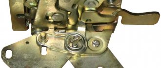
Rice. Position of the lock and latch when closing the door: I - direction of door movement; II - direction of rotation of the rotor; a - the door is completely closed; b - the door is closed by one tooth; c — the door begins to close; 1 - rotor; 2 - latch; 3 - cracker; 4 — clamp; 5 — latch shelf
Pivoting front door glass
The rotary glass, which serves for ventilation of the front part of the body, is a separate unit, which is attached to the door frame with two self-tapping screws screwed into brackets 9, and to the door sill with one screw screwed into a fixed nut 3. The rotary glass of the front door is pressed together with the rubber - a new gasket into the rotating frame and holds firmly in it.
The rotating glass frame is equipped with a friction mechanism that locks the glass in any position, even with strong pressure from the oncoming air flow.
The ease of movement of the glass, which should turn with little hand effort, and the reliability of its fixation depend on how tight the spring 6 is, creating friction between the washer 7, put on the lower axis 5 of the turning frame, and the bracket 4 of the glass mounting frame.
Since the pivoting glass is assembled into one unit along with the installation frame and the window dividing post, if it is necessary to adjust the spring tension, the entire unit must be removed from the door, which can only be done after removing the armrest, internal door handles and its upholstery.
In the closed state, when the glass handle 11 is held by the latch 12, the glass frame and its open edge must be tightly pressed along the entire contour to the rubber seals 1 and 8.
The window handle has a locking device with a button 10, which prevents the locked handle from turning upward (from a horizontal position) and opening the window from the outside of the car using any hook. When you press the button from inside the body, the glass handle rotates freely. When lowered to the horizontal position, the handle locks without pressing the button.
ABS is different
In the most expensive, and therefore most efficient, four-channel systems, each wheel has individual brake fluid pressure control. Naturally, the number of angular velocity sensors, pressure modulators and control channels in this case is equal to the number of wheels. All four-channel systems perform the EBD function (adjustment of braking forces along the axes). Cheap ones cost one common modulator and one control channel. In such ABS, all wheels are released when at least one is blocked. The most widely used system is with four sensors, but with two modulators (one per axis) and two control channels. In them, the pressure on the axle is adjusted according to a signal from a sensor of either the worst wheel or the best one. Finally, they release a three-channel system. Three modulators of this system serve three channels, individually regulating the brake fluid pressure in the lines of the front wheels separately and both rear wheels.
Do you think that the brake fluid pressure in the brake line is created only by the master cylinder? Not at all. Often he is helped by a special hydraulic pump built into the system. In the latest ABS, a computer is used to evaluate the dynamics of the vehicle, the angle of inclination of the road surface, adhesion to the road surface, the effect of the activated cruise control when the vehicle slows down and other factors and, based on this information, determines the required pressure in the brake line. Having determined the required pressure value, it is provided by supplying or bleeding brake fluid into the hydraulic accumulator.
On most vehicles with anti-lock braking systems, braking on loose snow and gravel will be much greater than on other vehicles (due to the effect of a bead of soil or snow collecting in front of a locked wheel). On the latest ABS blocks, they recognize the type of support surface by relative slip and allow the wheels to be locked. Such systems will not light up the fault light when spinning the wheels on a lift (for example, when diagnosing wheel bearings), although this will certainly be noted in the memory.
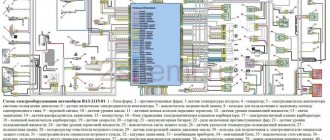
Operating principle of control unit central locking
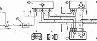
Let's look at the diagram attached to the installation instructions for Convoy X400 locks:
The actuator motors are connected “in parallel”. Blue and green wires are power. The black cord is the mass, but the “white” and “brown” cables are the control ones. In secret, let's say that the brown cord is the locking input, that is, closing occurs when it is connected to ground.
If the pawl on the driver's door is forcibly closed, the limit switch in the main actuator is triggered, and the brown cord is on ground. The block immediately supplies voltage to all actuators (locking occurs). To unlock the lock, you need to achieve the following: there is no ground on the “brown” cable, but there is ground on the “white” cable. Then the actuator rods extend. And the wires for “Manual Switch” are additional inputs, but they are controlled in the same way.
One thing needs to be noted. If the cord, white or brown, is shorted to ground for a long time, then everything works as it should. That’s why the “Manual Switch” should be a toggle switch, not a button.
Although, a double button can also serve as a switch, but on the condition that it is pressed for 0.8 seconds (continuously). Based on this property, the alarm can be connected to the control wires of the central locking system. The holding time of the relay in the signaling is set to 0.7-0.8 s, and this turns out to be enough.
Window lifter
For the sliding windows of 1 doors, the same window lifters with a cable drive are used. The glass lifters of the right and left doors are interchangeable, and the front and rear doors differ only in the length of the cable. The window regulator is secured to the door with three screws screwed into the window regulator body.
The window lift cable is fixed to drum 17 and in the working position is tensioned in the form of a triangle. The axis of the upper roller 4 is riveted to the reinforcement of the inner door panel.
The lower roller 14 is fixed in a fork 12, which is constantly pulled down by a spring 11 to compensate for the pulling of the cable. To reduce the friction of the cable on the side of the roller and ensure silent operation, the hook 10 of the fork is fixed at one point, as a result of which the plane of rotation of the lower roller 14 can deviate in accordance with the movement of the cable 16 along the grooves of the window lift drum 17.
Rice. Sliding glass and front door windows: 1 - glass; 2 — internal glass seal; 3 - window sill invoice; 4 - upper roller; 5 — cable clamp; 6 — external glass seal; 7 — external decorative trim; 8 — sliding glass holder; 9 — lower roller bracket; 10 - fork hook; 11 - spring; 12 - fork; 13 — buffer bracket; 14 - lower roller; 15 - buffer; 16 — cable; 17 - drum; 18 - handle
The cable and glass are moved by rotation of the drum using the window lifter roller gear and the drum ring gear 17.