The car engine starting system performs the initial rotation of the internal combustion engine crankshaft, as a result of which the fuel-air mixture in the cylinders ignites and the power unit begins to work independently.
The main task of the starting system is to rotate the crankshaft, which allows the piston to perform the compression of the mixture in the cylinders necessary to ignite the charge. Then the fuel ignites (from an external source in gasoline engines, from strong compression and heating in diesel engines).
Next, the crankshaft begins to rotate independently, that is, the engine starts, the crankshaft speed increases, and shaft rotation becomes possible due to the conversion of the thermal energy of fuel combustion into mechanical work. As soon as the crankshaft speed reaches a certain frequency, the starting system is automatically switched off.
In this article we will look at how the electric engine starting system works, what basic elements it consists of, and also talk about what other internal combustion engine starting systems there are, besides electrical solutions.
What is
Modern cars have an electric engine starting system. It is also often called a starter starting system. Simultaneously with the rotation of the crankshaft, the timing, ignition and fuel supply systems are switched on. The air-fuel mixture is burned in the combustion chambers and the pistons rotate the crankshaft. After reaching a certain crankshaft speed, the engine begins to work independently, by inertia.
Engine starting
To start the engine, you need to reach a certain crankshaft speed. This value differs for different types of engines. For a gasoline engine, the minimum required is 40-70 rpm, for a diesel engine - 100-200 rpm.
At the initial stage of the automotive industry, a mechanical starting system using a crank was actively used. It was unreliable and inconvenient. Now such solutions have been abandoned in favor of an electric starting system.
The starting system provides the initial cranking of the crankshaft when starting the engine.
In order for the engine to start working on its own, its crankshaft must be given a certain initial (starting) rotation speed. For these purposes, an electric starter is used, which provides a starting speed of the crankshaft: for gasoline engines 40...100 rpm, and for diesel engines up to 250 rpm. The starting frequency depends on the conditions of mixture formation and engine ignition and is the minimum crankshaft speed at which flashes begin in the cylinders.
Starter power depends on the moment of resistance to turning the crankshaft and the starting frequency. The moment of resistance to turning is proportional to the engine displacement and consists of the following components:
— the moment of friction forces between the mating surfaces of engine parts and in auxiliary mechanisms associated with the crankshaft;
— moment of inertial forces, increasing with increasing speed during engine starting;
- moment of resistance arising due to compression processes occurring in the engine cylinders.
On special and tractor equipment, some engines have a decompression mechanism to facilitate starting.
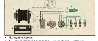
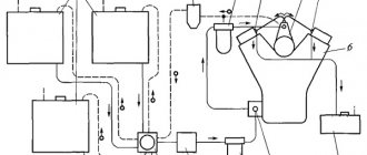
The circuit diagrams of electric starting systems for gasoline engines differ slightly from each other (Fig. 2.1). Electric starter control systems are equipped with electromagnetic traction relays
with
a drive mechanism
,
additional relays
,
a blocking relay
that provides remote activation, automatic disconnection of the starter from the battery after starting the engine and preventing the starter from turning on when the engine is running.
The source of energy for electric starting is the starter battery.
.
Electric starters use DC motors
. The characteristics of a starter electric drive with DC electric motors of series or mixed excitation are in good agreement with the nature of the load created by the piston engine during startup.
On tractor, special, and automotive equipment operating in special climatic conditions, electrical devices are often used to facilitate starting
.
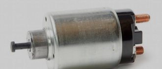
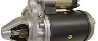
The classic starter (Fig. 2.6) is a DC electric motor with a drive mechanism controlled by a traction relay and powered by a battery. Typically, such starters have a gear on the armature shaft, with the help of which gearing is carried out with the rim of the engine flywheel. In this case, the gear ratio of the gear drive is 10...18 and is limited by the strength characteristics of the drive teeth.
The current strength in the starter windings can be 200...500 A and higher. As the rotation speed of the armature increases, the current in the windings decreases and the torque on the armature shaft decreases accordingly. This law of change in torque is most favorable for starting the engine, since at the beginning of cranking the resistance moment is greatest.
Typically, starters have a design where the stator winding in them is connected in series with the armature winding (Fig. 2.2) - these electric motors have series excitation. Starter torque depends on two factors: the stator magnetic field and the armature current, so a series-wound motor is preferable when high torque is required. When the starter is turned on, at the moment the electric motor starts, the current consumption is maximum and is limited only by the resistance of the windings. Such starters can develop very high speeds without load, and therefore it is not recommended to start them without load.
Rice. 2.1. Typical electric starter circuit
Rice. 2.2. Series-wound DC motor:
a) basic structure;
b) starter circuit with sequential excitation
1-excitation winding; 2-pole magnet (magnetic core); 3-anchor; 4-brushes; 5-collector; 6-battery; 7-ignition switch
In addition to series-wound motors
, there are also electric motors of mixed excitation, independent and electric motors with excitation from permanent magnets (Fig. 2.3).
Electric motors with independent power supply of the excitation winding
(Fig. 2.3 d) are not used in electric starting systems for automobile and tractor equipment, since there is only one starting source on board - the battery.
Electric motors with parallel excitation
(Fig. 2.3. a) in automobile electric starters are ineffective when operating in cold conditions (–20 ºС), and also have a rigid excitation characteristic, which is unacceptable at small gear ratios, as this can lead to breakage of the teeth and drive.
Mixed excitation of starter motors
(Fig. 2.3 c) allows you to combine the advantages of the favorable characteristics of series excitation with smooth operation and limitation of maximum speed due to parallel excitation. Such electric motors have a moderately hard excitation characteristic.
Rice. 2.3. Types of excitation of starter motors and their characteristics:
a) parallel; b) sequential; c) mixed; d) from permanent magnets; e) independent
, a design with independent and uncontrolled excitation from permanent magnets has increasingly been used.
.
Such starters have a reduction planetary gearbox in their design. This combines a relatively rigid excitation characteristic and a minimum starting frequency at maximum load. 2.2. Electric starter with sequential and mixed excitation
Pre-engagement starter
Let's consider the design and principle of operation of a starter with preliminary engagement (Fig. 2.4). The starter motor 10 is powered from the battery through closed contacts 1 of the traction electromagnetic relay. When the contacts of the instrument switch S
and the starter, the additional relay and the blocking relay are closed, the retractor 4 and holding 5 windings of the traction relay are connected to the battery. The armature 6 of the traction relay is attracted to the magnetic core of the electromagnet and, using the rod 7 and lever 9 of the drive mechanism, engages the gear 13 with the ring gear 14 of the engine flywheel.
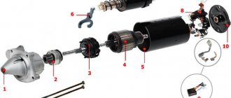
Rice. 2.4. Pre-engagement electric starter control circuit: 1-pin bolts; 2-movable contact plate; 3-return spring; 4.5 - retracting and holding windings of the traction relay, respectively; 6-armature traction relay; 7-rod; 8-excitation winding; 9-lever of the drive mechanism; 10-electric starter; 11-drive coupling; 12-freewheel; 13-gear drive; 14-tooth flywheel
After starting the engine, freewheel 12 (Fig. 2.5) prevents the transmission of torque from the flywheel to the armature shaft of the electric motor. The rollers are pressed by springs in the direction of rotation of the armature, and they are either wedged between the driving and driven links of the clutch when the speed of the armature is equal to the speed of the engine, or they are allowed to rotate freely when the engine reaches a speed greater than the armature.
The drive gear does not disengage with the flywheel ring until contact bolts 1 are closed (Fig. 2.4). When switch S
the pull-in and holding windings of the traction relay are connected to the battery in series through power contact bolts 1. Since the number of turns of both windings is the same and a current of the same strength passes through them when connected in series, then when the switch
S
, two equal but oppositely directed magnetic flux. The magnetic core of the electromagnet will be demagnetized, and the return spring will move the armature 6 of the relay to its original non-working position, thereby disengaging the gear from the flywheel ring. At the same time, the power contact bolts 1 will also open. A typical design of a starter with pre-engagement is shown in Fig. 2.6.
Rice. 2.5. Freewheel:
1-buffer spring; 2-outer race (driving link); 3-inner race (driven link); 4-rollers; 5-gear
Engine starting system device
The engine starting system includes the following key elements:
- control mechanisms (ignition switch, remote start, Start-Stop system);
- accumulator battery;
- starter;
- wires of a certain cross-section.
Engine starting circuit
The key element of the system is the starter, which, in turn, is powered by the battery. This is a DC motor. It creates torque, which is transmitted to the flywheel and crankshaft.
Types of starters
As described above, modern starters do not use shoes with an excitation winding, but magnets. Magnets as a stator can significantly reduce the dimensions of the device. In this case, the rotation speed of the armature increases. Therefore, a gearbox is sometimes used.
Based on this, starters are divided into:
- gear;
- simple (gearless).
We have already become familiar with the structure and operation of a simple starter. The operation of a gearbox is based on the same principles as a simple one, but has a slightly different device. The torque from the armature first goes to the planetary gearbox, which converts it, and then to the bendix shaft. Rotation from the armature to the gear is transmitted through the planetary gear carrier.
This type of starter has the following advantages:
- higher efficiency;
- less current consumption;
- small sizes;
- starting the engine even when the battery charge is low.
But this design affects the complexity of repairs.
How does engine starting work?
After turning the ignition key to the “start” position, the electrical circuit is closed. The current through the positive circuit from the battery is supplied to the winding of the starter traction relay. Then the current passes through the field winding to the positive brush, then through the armature winding to the negative brush. This is how the traction relay works. The movable core retracts and closes the power pins. When the core moves, the fork extends, which pushes the drive mechanism (Bendix).
After the power nickels are closed, starting current is supplied from the battery through the positive wire to the stator, brushes and rotor (armature) of the starter. A magnetic field appears around the windings, which sets the armature in motion. In this way, the electrical energy from the battery is converted into mechanical energy.
Operation of the starter turned off and on
As already mentioned, the fork, during the movement of the retractor relay, pushes the bendix towards the flywheel crown. This is how engagement occurs. The armature rotates and drives the flywheel, which transmits this movement to the crankshaft. After starting the engine, the flywheel spins up to high speeds. To avoid damaging the starter, the Bendix overrunning clutch is engaged. At a certain frequency, the bendix rotates independently of the armature.
After starting the engine and turning off the ignition from the “start” position, the bendix returns to its original position, and the engine runs independently.
Bendix device
Bendix is a rather interesting device. It is sometimes called a freewheel or overrunning clutch.
Bendix
To start the engine, the flywheel must rotate no slower than 100 rpm. Since the starter gear is much smaller than the flywheel ring gear, it needs to spin 10 times faster to give the flywheel the required acceleration. This is 1000 rpm.
When the engine starts, the flywheel begins to rotate very quickly. It transmits this rapid rotation to the gear. It is easy to calculate that the gear rotation speed will already be 10,000 rpm. If such acceleration was transmitted to the starter shaft, it would not be able to withstand it. This is exactly what Bendix is for. It transmits rotation from the gear to the flywheel, but does not transmit it back from the flywheel to the gear.
Bendix in analysis
The Bendix itself consists of two parts: the gear and the housing. The inner race of the gear fits into the housing with the outer race. Inside this clip there are four rollers with springs. The bendix housing rotates through the starter shaft. When rotating, the inner race of the gear seems to jam in the housing and rotates, and when the gear rotates from the flywheel, these rollers diverge and do not transmit rotation to the shaft. The starter shaft itself rotates at the same speed.
Features of battery operation
Successful engine starting will depend on the condition and power of the battery. Many people know that such indicators as capacity and cold cranking current are important for batteries. These parameters are indicated on the marking, for example, 60/450A. Capacity is measured in Amp-hours. The battery has low internal resistance, so it can deliver large currents for a short time, several times its capacity. The specified cold cranking current is 450A, but subject to certain conditions: +18C° for no more than 10 seconds.
However, the current supplied to the starter will still be less than the specified values, since the resistance of the starter itself and the power wires is not taken into account. This current is called inrush current.
Reference. The internal resistance of the battery is on average 2-9 mOhm. The starter resistance of a gasoline engine is on average 20-30 mOhm. As you can see, for proper operation it is necessary that the resistance of the starter and wires be several times higher than the resistance of the battery, otherwise the internal voltage of the battery during startup will drop below 7-9 volts, and this should not be allowed. When current is applied, the voltage of a working battery drops to an average of 10.8V for a few seconds, and then recovers again to 12V or slightly higher.
The battery supplies starting current to the starter for 5-10 seconds. Then you need to pause for 5-10 seconds for the battery to “gain strength”.
If, after attempting to start, the voltage in the on-board network drops sharply or the starter cranks halfway, this indicates a deep discharge of the battery. If the starter makes characteristic clicks, then the battery is completely dead. Other reasons may include a broken starter.
Current strength at start
Starters for gasoline and diesel engines will differ in power. For gasoline internal combustion engines, starters with a power of 0.8-1.4 kW are used, for diesel engines - 2 kW and higher. What does it mean? This means that a starter with a diesel engine needs more power to rotate the crankshaft into compression. A 1 kW starter consumes 80A, a 2 kW starter consumes 160A. Most of the energy is spent on the initial rotation of the crankshaft.
The average starting current for a gasoline engine is 255A for successful cranking, but this takes into account a positive temperature of 18C° or higher. At sub-zero temperatures, the starter needs to turn the crankshaft in thickened oil, which increases resistance.
Features of starting the engine in winter conditions
In winter it can be difficult to start the engine. The oil thickens, which means it is more difficult to turn it. The battery also fails frequently.
At sub-zero temperatures, the internal resistance of the battery increases, the battery drains faster, and is also reluctant to deliver the required starting current. To successfully start the engine in winter, the battery must be fully charged and not frozen. Additionally, you need to monitor the contacts on the terminals.
Here are some tips to help start your engine in winter:
- Before turning on the starter when cold, turn on the high beams for a few seconds. This will start chemical processes in the battery, so to speak, “wake up” the battery.
- Do not turn the starter for more than 10 seconds. This way the battery drains quickly, especially in the cold.
- Depress the clutch pedal fully so that the starter does not have to turn additional gears in the viscous transmission oil.
- Sometimes special aerosols or “starter fluids” that are injected into the air intake can help. If the engine is in good condition, it will start.
Thousands of drivers start their engines every day and go on business. Getting started is possible thanks to the coordinated operation of the engine starting system. Knowing its structure, you can not only start the engine in a variety of conditions, but also select the necessary components in accordance with the requirements specifically for your car.