The car’s braking system (English – brake system) refers to active safety systems and is designed to change the speed of the car until it comes to a complete stop, including an emergency stop, as well as to hold the car in place for a long period of time. To implement the listed functions, the following types of brake systems are used: service (or main), spare, parking, auxiliary and anti-lock braking systems (exchange stability system). The totality of all braking systems of a car is called brake control.
Working (main) brake system
The main purpose of the service brake system is to regulate the speed of the vehicle until it comes to a complete stop.
The main braking system consists of a brake drive and brake mechanisms. In passenger cars, a hydraulic drive is predominantly used.
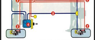
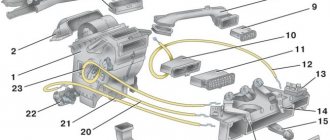
Car brake system diagram
The hydraulic drive consists of:
- master brake cylinder (MBC);
- vacuum booster;
- pressure regulator in the rear brake mechanisms (in the absence of ABS);
- ABS unit (if equipped);
- working brake cylinders;
- working circuits.
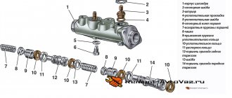
The brake master cylinder converts the force applied by the driver to the brake pedal into the pressure of the working fluid in the system and distributes it among the operating circuits.
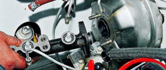
To increase the force creating pressure in the brake system, the hydraulic drive is equipped with a vacuum booster.
The pressure regulator is designed to reduce the pressure in the brake drive of the rear wheels, which contributes to more efficient braking.
Types of brake system circuits
The brake system circuits, which are a system of closed pipelines, connect the main brake cylinder and the wheel brakes.
Circuits can duplicate each other or perform only their functions. The most popular is the dual-circuit brake drive circuit, in which a pair of circuits operate diagonally.
Dividing systems into independent circuits
Braking systems can be single-circuit, double-circuit and multi-circuit.
In single-circuit solutions, the lines of all wheels - front and rear - are combined into one branch, and only one valve is used to control the air. The solution is cheap, not extremely unreliable. In practice, it can now only be found on some agricultural machines and trailers with pneumatics, and we are talking only about older machine models; new solutions with pneumatic drive are focused on several circuits.
If we are talking about solutions with a hydraulic drive, then depressurization is very likely, and the liquid will leak out of the system. And here there can be no question of using one circuit at all. Having multiple circuits helps prevent risks. Even if one of them depressurizes, even if there is a loss of efficiency, a disaster can be avoided. After all, the contours protect each other.
The most common option is to have two circuits. In this case, the schemes for dividing the hydraulic drive into 2 circuits can be very different:
- 2 +2, parallel connection. The 1st circuit acts on the brakes of the front axle, the second - on the rear axle). Disadvantage: the rear axle provides no more than 40% of the braking forces. Therefore, if only the 2nd circuit is operational, the length of the braking distance (TD) will increase by 2.5-3 times.
- 2+ 2 – diagonal connection. The 1st circuit acts on the right front and left rear wheels, and the second - on the left front and right rear.
- Suitable for front wheel drive vehicles. A malfunction of any of the circuits is fraught with a doubling of the TP.
- 4 + 2. The 1st circuit acts on all wheels, and the second - only on the front ones.
The safest, from the point of view of experienced auto mechanics, is diagonal division (efficiency can be achieved even if one of the circuits is damaged) and the 4 + 2 division scheme.
Trucks and buses often have 4 and 5 circuits. These are complex but very reliable designs. Each circuit has its own area of responsibility (for example, front axle, rear bogie, parking, emergency brake release), and each circuit is independent. This is possible due to the presence of special separating valves in the design.
A multi-circuit pneumatic system optimizes the level of stability of a large vehicle and the process of controlling it. In addition, the pneumatic system allows you to connect and disconnect the pneumatic systems of the tractor to the trailer or semi-trailer without fear of loss of the working fluid. When the trailer is uncoupled, the parking fuel system is automatically activated.
The structure of the car brake system
Brake system
The basis of the braking system is the brake mechanisms and their drives.
The brake mechanism is used to create the braking torque necessary to brake and stop the vehicle. The mechanism is installed on the wheel hub, and its operating principle is based on the use of friction force. Brakes can be disc or drum.
Structurally, the brake mechanism consists of static and rotating parts. The static part of the drum mechanism is the brake drum, and the rotating part is the brake pads with linings. In a disc mechanism, the rotating part is represented by a brake disc, and the stationary part is a caliper with brake pads.
The drive controls the brake mechanisms.
The hydraulic drive is not the only one used in the braking system. Thus, the parking brake system uses a mechanical drive, which is a combination of rods, levers and cables. The device connects the rear wheel brakes to the parking brake lever. There is also an electromechanical parking brake, which uses an electric drive.
The hydraulically driven braking system can include a variety of electronic systems: anti-lock braking, stability control, emergency brake assist, and Brake Assist System.
There are other types of brake drive: pneumatic, electric and combined. The latter can be presented as pneumohydraulic or hydropneumatic.
Frequency of replacement of pads and brake discs
In all of the above cases, you must contact a professional service to repair or replace faulty brake system components. But the best thing is to prevent critical wear of parts. For example, the difference in the thickness of a new and worn brake disc should not exceed 2-3 mm, and the residual thickness of the pad material should be at least 2 mm.
It is not recommended to be guided by the mileage of the car when replacing brake elements: in city driving conditions, for example, the front pads can wear out after 10 thousand km, while in country trips they can withstand 50-60 thousand km (rear pads, as a rule, , wear out on average 2-3 times slower than the front ones).
You can assess the condition of the brake elements without removing the wheels from the car: there should be no deep grooves on the disc, and the metal part of the pad should not lie close to the brake disc.
The principle of operation of the braking system
The brake system works as follows:
- When the driver presses the brake pedal, a force is transmitted to the vacuum booster.
- It is then increased in the vacuum booster and transferred to the main brake cylinder.
- The GTZ piston forces working fluid to the wheel cylinders through pipelines, due to which the pressure in the brake drive increases, and the pistons of the working cylinders move the brake pads to the discs.
- Further pressing of the pedal increases the fluid pressure even more, due to which the brake mechanisms are activated, leading to a slowdown in the rotation of the wheels. The pressure of the working fluid can approach 10-15 MPa. The larger it is, the more effective the braking occurs.
- Lowering the brake pedal causes it to return to its original position under the action of the return spring. The GTZ piston also returns to the neutral position. The working fluid also moves to the brake master cylinder. The pads release the discs or drums. The pressure in the system drops.
Important! The working fluid in the system must be changed periodically. How much brake fluid will be needed per change? No more than a liter and a half.
Varieties
Brakes on cars began to be used immediately from the moment cars appeared. The first systems were primitive and simple, but they coped with their task, since the speed of vehicles was low. As the car improved, the brakes were also improved. Various types of braking systems have also been developed with their own design differences and features.
In general, all types of braking systems used in transport can be divided into categories:
- Purpose
- type of drive
- Design of working mechanisms
Since this system must perform a number of functions, several types of brakes are used in the design of the car, and each of them has its own purpose.
Types by purpose
There are two types of brakes used on passenger cars - service and parking. Additionally, backup and exhaust brakes can be used on vehicles.
The worker slows down the machine until it stops moving completely. The peculiarity of their work is that the deceleration rate depends on the force of pressing the brake pedal.
The parking brake, as the name implies, is designed to immobilize a car while parked. Thanks to it, the wheels are blocked, and the car will not be able to roll away without permission.
The backup brake is also called the emergency brake. It is needed to ensure that the car stops if the working system breaks down. On passenger cars there is usually no backup brake as a separate system, and its function is performed by the parking brake.
The mountain brake is used on trucks. Its essence lies in the forced reduction of engine speed when driving downhill, which allows you to slow down the car without using the service brake to prevent overheating and failure of the working mechanisms.
Drive types
Existing types of braking systems also differ in the type of drive. The task of the drive is to transmit force to working mechanisms or perform certain actions with their components.
They can be divided into:
- Mechanical
- Hydraulic
- Pneumatic
- Combined
In the mechanical type, the driver acts on the working units through systems of rods, cables and levers. This type of drive is not usually used for service brakes, but it is often used for parking brakes.
Hydraulic is the most common drive on passenger cars. It is built on the physical property of liquid - incompressibility. This allows the use of liquid to transmit force to working mechanisms.
The design of a simple brake system
Pneumatic drive is used on trucks. Here the main working fluid is compressed air pumped by a compressor. The driver, by pressing the pedal, opens the channels through which air is supplied to special chambers associated with the working mechanisms.
Combined drives are usually used on special equipment. Such a drive may include structural elements of the listed types of drives. For example, it can be hydromechanical, electromechanical, etc.
Types of working mechanisms
The working mechanisms act on the wheels, slowing down their rotation. That is, these are the main elements of the braking system. They can be tape, disk or drum. The first type is practically not used and can only be found on special equipment. The essence of its work comes down to the fact that on the axis, which transmits rotation to the wheel, there is a drum with a tape on it. When braking, the driver acts on the belt, pulling it, and due to friction, the speed of rotation of the drum slows down.
Disc mechanisms are one of the most common on passenger cars. Here the main working element is a disk firmly mounted on the wheel hub. The system drive is connected to a caliper mounted on the brake disc. It has friction pads installed. When braking, the caliper presses the pads against the disc, and the friction between them slows down the rotation of the hub.
Drum brakes use a drum mounted on a hub instead of a disc. Inside it, on the stationary part of the hub, there are two pads in the form of crescents. When braking, the drive releases the pads, as a result they are pressed against the drum and slow down its rotation.
Basic malfunctions of the brake system
The table below shows the most common malfunctions of the car brake system and how to fix them.
| Symptoms | Probable Cause | Solutions |
| I hear a whistling or noise when braking | Wear of brake pads, their low quality or defects; deformation of the brake disc or contact with a foreign object | Replacing or cleaning pads and discs |
| Increased pedal travel | Leakage of working fluid from the wheel cylinders; air entering the brake system; wear or damage to rubber hoses and gaskets in the GTZ | Replacement of faulty parts; bleeding the brake system |
| Increased pedal force when braking | Vacuum booster failure; hose damage | Replacing the amplifier or hose |
| Braking of all wheels | Piston jamming in the GTZ; lack of pedal free play | Replacement of GTZ; setting the correct free play |
Questions about work
What is the service life of brake pads?
For most cars, the mileage of the pads until they are completely worn out is up to 60,000 km when driving in normal mode. The service life depends on driving style, and the presence of defects on the surface of the disc can significantly reduce it. Read more in the article - how to determine pad wear.
What are the stagnation temperatures?
Temperatures arising from friction between pads and discs normally do not exceed 370°C, even under heavy traffic conditions. During sports driving - about 480-650°C are normal, increasing to 820°C. The car's pads heat up to approximately this temperature when they acquire a reddish tint.
You shouldn't buy sports pads because you like to drive fast. The vast majority of them require preliminary “warming up” and will not work effectively at normal temperatures, and this is fraught with an emergency situation.
Why does the brake pedal become soft or hard?
Often the brake pedal feels “soft” at first after installing new pads. A certain period of time is required to grind in the rubbing surfaces. The pedal becomes “hard” after some time.
Are there any advantages to perforated discs?
They have some advantages - they destroy the surface film formed when the brakes overheat, maintain the cleanliness of the brake pad surface, removing combustion products formed on rubbing surfaces under the influence of high temperatures.
Drum and disc actuators
The main work during braking lies with the actuators, because they are the ones who slow down the rotation of the wheel.
Their work is based on the force of friction, which is why all brake mechanisms on cars are of the friction type.
Two types of such mechanisms have become widespread on cars - drum and disk.
Each of them has its own design features, advantages and disadvantages.
It is noteworthy that combining them is quite acceptable. So, in many cars, all mechanisms can be either only drum (usually on trucks) or only disc (many passenger cars).
But there is also a combination of them - disc mechanisms are installed on the front wheels, and drum mechanisms are installed on the rear wheels.
Disc type brake mechanism.
Nowadays, such a mechanism is increasingly used, due to a number of advantages over the drum type.
Structurally, it consists of several elements:
- Disk;
- Pads;
- Caliper.
The disc acts as one of the friction parts of the mechanism and is used to create friction during braking. It is fixed to the hub and rotates at the same speed as the wheel.
Pads are the second friction component. By pressing them against the disk, friction is created between these elements, which reduces the speed of rotation of the disk, and with it the wheel.
To increase the friction force, the pads have special friction linings.
The caliper design includes a drive working cylinder. It is this component that ensures the clamping of the pads.
There are different designs - both single-piston (the most common) and two-piston.
The design of this mechanism looks like this: a caliper with pistons is fixed above the disk, while the working pistons (one or two) are located perpendicular to the side surfaces of this disk.
Pads are placed between the caliper and the two lateral (working) surfaces of the disc. When the brakes are released, there is a gap between the friction components, so the pads do not interfere with the rotation of the disc.
Now a little about how mechanisms with single-piston and two-piston calipers work.
In the first case, the caliper can move along the guides, which allows you to simultaneously press both pads.
It works like this: when the pressure in the working cylinder increases, the piston comes out and begins to press the pad. This creates a reverse force that moves the caliper along the guides.
Shifting, he begins to press the second block with his body. As a result, the pressing force of the pads on both sides of the disc is equalized.
In a two-piston caliper, its movement is not provided, since each pad is pressed by its own piston.
Design and operation of the drum brake mechanism.
The design of the drum actuator differs from the disk one, and radically.
Its device includes:
- Drum;
- Pads;
- Double piston working cylinder;
- Shield;
- Tension springs.
As in the case of a disk mechanism, a drum mechanism has two friction components, between which friction occurs during braking. Here their role is played by a drum and two blocks made in the shape of a crescent.
The drum is a movable element; it is located on an axis and rotates along with the wheel. The stationary element is the shield with the working cylinder (top) and pad support (bottom) attached to it.
The pads (with friction linings) are placed so that their tops rest against the cylinder pistons and support.
They are held in this position by tension springs (top and bottom) and clamps. All elements located on the shield are placed inside the drum, that is, they are covered by it.
It all works very simply: when you press the pedal, the pistons come out of the cylinder and, overcoming the force of the springs, spread the pads.
This movement causes the pads to begin to press against the inner surface of the (working) drum, which slows down its rotation.
When the pedal is released, the springs return the pads to their original position.
Comparative characteristics.
As already noted, each of the types of mechanisms used has its own advantages and disadvantages.
The positive qualities of disk mechanisms include:
- High efficiency;
- Less response time;
- Due to the open design, ventilation is ensured (the mechanism is better cooled and wear products are removed);
- Quick removal of moisture;
- Easy to disassemble for maintenance and repair.
But at the same time, such mechanisms wear out faster, so their maintenance, with the replacement of consumables, must be carried out more often.
The open design also has its downsides.
Firstly, more foreign particles get between the pad and the disc, which increases the wear rate.
Secondly, it is much easier for moisture to get onto the working elements. Moreover, if the disk is very hot, there is a high probability of warping.
Also, such mechanisms are difficult to use as elements of a parking system.
As for drum mechanisms, their advantages include:
- Long service life without the need to replace consumables;
- The working elements are protected from foreign particles (they are closed);
- High drum resistance to sudden temperature changes;
- Possibility of use as a parking brake element (this is why such mechanisms are often used on the rear wheels).
But such brakes are less effective, there is a possibility of their failure when overheated, and they have a more complex design, which makes repairs more difficult.
In addition, destruction of the springs or the pads themselves can lead to jamming of the mechanism.
Mechanical brake
Mechanical brakes began to be used with the advent of drum brakes, installed between the wheel and its axle.
This type of brake consisted of mechanisms that included:
- Brake drum;
- Pads;
- Cam shaft and springs installed on each wheel axle;
- A control mechanism consisting of a system of cables and rods.
The driver, if necessary, influenced the control mechanism. Its force was transmitted to the cam shaft through rods and cables.
This shaft rotated and began to unclench the pads, forcing them to press against the drum. The resulting friction slowed down the rotation of the wheel.
This type of drive is no longer used as a service brake, except that it is still used as a parking brake, but only on cars equipped with drum mechanisms on at least one axle.
The science of stopping...
Here, friends, is a parachute brake that reduces speed and kinetic energy so that a pilot ejected from an airplane or from a simulator lands safely on the ground.
See also: Basic principles of operation of the car brake mechanism [Operation principle and elements of the brake system]
If you are moving, it means that you have energy, that is, kinetic energy to be precise. Kinetic energy is the energy that a certain object has because it has mass and velocity (speed in a certain direction). The more mass (that is, the heavier the object) and the faster you or the object moves, the more kinetic energy you or the object will have.
All this is of course good, but what if you suddenly need to stop? How do you go from moving quickly to not moving at all? To do this, you or the object need to get rid of its kinetic energy.
For example, if you are jumping from a high altitude from a flying airplane, then the best way for you to lose energy would be a parachute. Thanks to the giant “bag of fabric” that flies after you, the movement slows down, that is, the speed of the fall decreases, and therefore the parachute helps you get rid of your own kinetic energy.
As a result, the parachute allows you to land safely and smoothly on the ground unharmed.
By the way, powerful dragster cars, which are record holders for acceleration from a standstill and with them sports cars that can accelerate to record speeds, also use parachutes for stopping. But most ordinary cars, as you yourself know, use a traditional hydraulic braking system, which was invented at the beginning of the 20th century, to stop and reduce speed.
Braking mechanism design
The brake system on modern cars may include 3 or 4 circuits that perform different tasks. These include:
- Basic.
- Duplicate.
- Parking (manual, mountain).
- Auxiliary.
Working system
The main role among the listed systems is played by the main (working) one. It is used directly while driving and is designed to slow the vehicle down (if necessary) to a complete stop. There are two types of working systems:
- Disk.
- Drum.
We recommend: Optimal volume of antifreeze in the VAZ-2110 cooling system
Special pads in mechanisms of the first type, when pressing the pedal, compress the disk on both sides, preventing it from rotating and stopping the wheel. In systems of the second type, the pads are installed inside the wheel drum. When you press on the pedal, they expand it, preventing the wheel from rotating.
Backup brake
The backup mechanism plays a safety role, coming into operation if the main one fails. On some models it completely duplicates the rear as well as front brakes, on others its action is distributed only to one of the parts (most often to the rear cylinders). Sometimes this function is assigned to the handbrake.
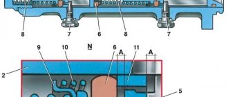
Parking mechanism
The parking (mountain, hand) brake is designed to ensure the stability of the machine in the parking area. By releasing the brake pedal, the driver disables the main system. If the area chosen for stopping has even a slight slope, the car can easily roll and will not stop until it hits something in the way. The “something” could be another car, the side of a building, or a tree, and damage is virtually guaranteed. An additional function of the handbrake is to hold the car on a slope if it stalls during an ascent. In this case, in order to move off, the driver smoothly releases the clutch while simultaneously pressing the accelerator and lowering the exhaust brake lever. If these actions are performed simultaneously, the car will not roll back.
Handbrake drive VAZ 2106: 1 - cover; 2 — front cable; 3 - lever; 4 — button; 5 — thrust spring; 6 — latch rod; 7 — bushing; 8 - roller; 9 — rear cable guide; 10 — spacer sleeve; 11 — tension spring; 12 — rear cable; 13 — rear cable bracket
Assistance system
Auxiliary brake mechanisms are installed on large and heavy vehicles used to transport various cargo over long distances. They allow you to partially relieve the main system when the car is slowed down for a sufficiently long time on roads passing through hills or located in the mountains.