When designing the small car VAZ Oka 1111 and 11113, many components and mechanisms were “borrowed” from other VAZ models, which made it possible to reduce the cost of car production and speed up the start of production. But the designers had to significantly rework some components in order to adapt them to the features of the Oka engine. One of these components is the ignition system.
When creating the ignition system, the designers used modern developments of those years. The VAZ Oka received a non-contact ignition system. At the same time, the features of the power plant made it possible to somewhat simplify the system and reduce the number of components, which had a positive impact on the reliability of this component of the power plant.
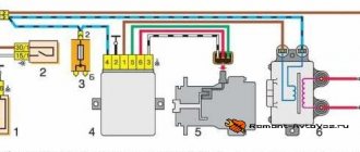
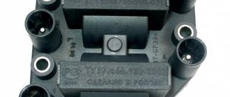
Switch Connection Diagram
If the indicated elements are in working order, and the fault has not been resolved, the ID1 chip should be replaced. To avoid failure of the VAZ ignition system switch, when the ignition is on, do not disconnect it from the circuit and do not remove the battery terminals even when the power plant is running.
But the plus of the Hall sensor is connected to ground.
In this case, the engine starts poorly, runs intermittently, stalls at idle, loses power, or its speed constantly fluctuates. That is, if the induction reaches a certain threshold, the sensor outputs the presence of the field in the form of a certain logical unit, if the threshold is not reached, the sensor outputs a logical zero. How to connect BSZ correctly
But there are still many cars on the roads that have both contact breakers and contactless ones.
A flash forms in the combustion chamber, the fuel mixture ignites and pushes the piston down. Only the signal from the Hall sensor is used. Switch
It is part of the design of another element - the ignition distributor.
How a switch works Essentially, a switch is a simple signal amplifier.
How to connect a switch or ignition control unit to a Chinese
How to save the diagram on your computer, see previous articles, for example here. I'm tired of writing the same thing in all my articles :).
Description and diagram of Oka:
- Front turn signal lamps
- Headlights
- Electric motor driving the cooling fan
- Audible tone
- Sensor automatically turns on the fan motor on the radiator
- Starter
- Electric windshield washer
- Generator
- Oil pressure lamp sensor
- Temperature sensor for coolant temperature indicator (antifreeze, water)
- Plug socket for portable lamp
- Electronic ignition switch
- Spark torque sensor
- Candles
- Accumulator battery
- High-voltage ignition coil for two spark plugs
- Frog switch for automatically turning on the lights in the reversing lights
- Solenoid valve located on the carburetor
- Electric windshield wiper
- Sensor for monitoring the brake fluid level in the reservoir
Wiring diagram VAZ-1111-Oka
- Fuse block panel
- Relay-breaker for the lamp for monitoring the position of the parking brake lever
- Radiator fan power relay
- Starter Bendix Voltage Relay
- Relay for supplying voltage to the rear window heating element
- Relay for supplying voltage to the spiral of the high beam lamps
- Relay for supplying voltage to the spiral of the low beam headlight lamps
- Voltage breaker relay in the direction indicator and hazard warning light circuits
- Ignition relief relay
- Ignition switch (lock)
- Individual taillight fog light circuit fuse
- Switch for different operating modes of the windshield wiper
- Button for activating the windshield washer
- Switch-button for sound signal
- Switch (lever) for switching between high and low beam headlights
- Switch (lever) direction indicators
- Brake pedal button
- Switch for rear window wiper and washer
- Fixed button that turns on the rear window defroster
- Rear fog light switch
- Indicator lamp, carburetor damper position
- Fixed hazard warning light button
- Multi-position switch for outdoor lighting devices
- Cigarette lighter socket
- Engine coolant temperature reading device
- Combined control panel
- Heater motor speed switch
- Illumination lamp from inside the instrument cluster
- Additional active resistance (resistor) in the heater motor circuit
- Indicator lamp for reserve fuel level mode
- Heating turbine electric motor
- Fuel level indicator
- Button-limit lamp for monitoring the carburetor air damper
- Side redundant turn signal repeaters
- Light switches in the cabin, located in the door pillars
- Parking brake control lamp switch
- Lamp in the cabin
- Rear window washer motor
- Sensor in the tank of the indicator device for monitoring the level and reserve of fuel
- Warning light for parking brake lever and level in brake fluid reservoir
- Warning lamp for emergency pressure in the engine lubrication system
- Emergency warning lamp in the battery charging system
- Rear window heating element
- Turn signal control lamp
- External lighting control lamp
- Indicator lamp indicating that the headlights are on high beam
- Rear block lights
- Rear window wiper motor
- Flashlights with license plate illumination lamps at night
- Rear fog light(s)
- Wiring diagram Renault Symbol (0)
- Electrical diagrams of CHERY TIGGO from 2005. (0)
- Chevrolet Lacetti wiring diagram. (0)
- Wiring diagrams for Renault Megane NT8169A version from October 1999 (0)
- TagAZ wiring diagrams (0)
A. An example of the order of conditional numbering of connectors in the blocks.
Similar auto electrical circuits
Author: admin Last edited: 14 Aug 2011 at 21:21
Fuse box diagnostics (video)
VAZ-1111 especially small class passenger cars are equipped with 12-volt electrics with a negative terminal connected to the car body. The cars were equipped with carburetor and injection power units, which had little effect on the location and purpose of the circuits. The VAZ-1111 electrical circuit, which is basic for all versions of the Oka, can be used when repairing a car of any year of assembly.
What is included in the Oka electrical circuit?
Electrical diagram of VAZ-1111 with symbols
Electrical diagram of VAZ-11113 with symbols
Contactless ignition diagram indicating the main elements and connecting wires
Fuse diagram for VAZ-1111 and 11113
Common electrical faults
Models, design and characteristics of VAZ switches
Electronic switches used on VAZ cars are divided into two large groups:
- Transistor;
- Based on specialized microcircuits.
The device of a modern VAZ switch
Typical connection diagram for an electronic switch
The simplest design is for transistor switches, which were historically the first (they replaced contact-transistor devices that were widely used on VAZ Classic cars). In essence, this is an electronic key, complemented by a signal amplifier from the pulse sensor, as well as protection and temperature compensation elements. The key is built on one powerful transistor, which is controlled by one or two transistors that amplify and change the signal from the Hall sensor. Zener diodes included in the circuit (prevent voltage surges), thyristors (disabling the switch or its individual elements in emergency modes) and other parts can act as protection elements. And temperature compensation elements (chains of resistors and capacitors) ensure constant operating modes of semiconductor devices over the entire permissible temperature range.
The operation of a transistor switch is quite simple. While there is no signal from the Hall sensor, the electronic key is open and a direct current flows through the primary winding of the coil - at the moment there is no current in the secondary winding. When a signal is received from the sensor, the switch closes, interrupting the current in the primary winding. Due to the presence of inductance, the current in the primary winding does not drop to zero instantly, but over a certain period (fractions of a second), the phenomenon of electromagnetic induction occurs - as a result of this effect, high-voltage alternating current also appears in the secondary winding. This current flows through the distributor to the spark plug, where sparking and ignition of the combustible mixture occurs. At a subsequent moment, a direct current again flows through the primary winding, so the current disappears again in the secondary winding. Then the described processes are repeated again up to 200-300 times per second.
Transistor circuitry is incorporated into the switch model 76.3734. This device is simple and reliable, but it has a number of disadvantages. For example, as the crankshaft rotation speed increases, the current in the secondary winding decreases significantly; the switch also has limited functionality and cannot ensure efficient operation of the ignition system in all modes.
Electronic switches based on specialized microcircuits do not have these disadvantages. This switch also uses an electronic key on a powerful transistor, but the key control is assigned to a microcircuit, which significantly expands the functions and capabilities of the entire device. In particular, switches with microcircuits implement functions for regulating the time of energy accumulation in the coil, spark-free cutoff (limiting spark formation when the ignition is on but the engine is stopped), various levels of protection, and others. Thanks to the ability to regulate the energy storage time, switches on microcircuits provide stable sparking throughout the entire crankshaft speed range, which is why they are so widespread.
Oka switch connection diagram
First of all, let's get acquainted with the ignition system of the GAZ-3307 truck. The ignition system of the GAZ-3307 is battery-based, contactless transistor with a voltage in the primary circuit of 12V, consists of electric current sources, an ignition coil, an additional resistor (if I’m not mistaken, where since 2000 they have been produced without an additional resistor), a switch, an ignition distributor, spark plugs, plug tips, ignition switch and low and high voltage wires.
Technical characteristics of the ignition system of GAZ-3307 (GAZ 53) cars
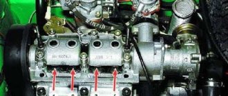
Ignition order of GAZ-3307 1 - 5 - 4 - 2-6 - 3 -7 - 8 Type of ignition distributor (distributor) - 24.3706 Distributor shaft rotation speed per 1 min with uninterrupted spark formation when working with a B116 ignition coil on a three-electrode spark gap at spark gap 7 mm, min-1 - 20 - 2300 Direction of rotation of the ignition distributor roller (distributor) GAZ-3307 - clockwise Ignition coil GAZ-3307 - B116 Spark plugs - A11 Spark gap size in spark plugs, mm - 0.8 - 0.95 Additional resistor - 14.3729 Switch - 131.3734 or 13.3734 Spark plug tip - 35.3707200
Diagram of the GAZ-3307 ignition system
And so, as I already said in our time, the ignition system of the GAZ-3307 truck has undergone minor changes.
As I already wrote, this happened after 2000, this is approximately what I am saying. I can’t say for sure, I’m afraid I’ll make a mistake, but I didn’t bother googling and searching for it; I just don’t have time for it and it’s not particularly interesting. If you are interested, look for it and then share it with me. You can leave a comment.
This applies to transistor switch brands 13.3734 and 131.3734
You can see the difference is just one number, that is, it was 13.3734 before 2000, but they began to produce the GAZ-3307 after 2000 with a switch of 131.3734. And so there is only one number and this is one number, that is, as you noticed, number 1 removes the additional resistor from the GAZ-3307 ignition system - 14.3729.
That is, simply put, the function of the additional resistor is 14.3729. built into the transistor switch 131.3734.
I want to warn you, someone may say “yes, I put brand 13.3734 instead of brand 131.3734 and why doesn’t the machine work?” I agree with him.
GAZ-3307 will of course work and go normally, but not far. Why, you ask, of course, and you will be right, you need to find out why ? Yes, because your ignition coil (bobbin) will simply burn out.
Why this will happen : The ignition coil, GAZ-3307 (B 116) is a transformer, on the iron core of which the secondary winding is wound, and on top of it is the primary winding. The core with windings is installed in a sealed steel case filled with oil and closed with a high-voltage plastic cover.
Operating temperature from -50° C to +80° C. Resistance value at a temperature of 25° C: primary winding (0.65+0.07) Ohm, secondary winding (18+1.8) kOhm.
Developed secondary voltage 18 kV max. Supply voltage 12 V. Weight 0.95 kg. During operation, the B-116 ignition coil is supplied with reduced voltage through an additional resistor-14.3729 . The resistor heats up during operation, this is normal. The resistor, when the starter is turned on (when starting the engine), is bypassed and the coil is supplied with full voltage (more precisely, the on-board voltage supplied by the starter), this makes starting easier.
the additional resistor 14.3729 takes up “work” again . And now give yourself this picture of a GAZ-3307, well, let’s say after the year 2000, there is, of course, ignition without an additional resistor - 14.3729 and an ignition coil B-116 and a transistor switch 131.3734, and you took and installed a transistor switch 13.3734, and what next GAZ-3307 Of course, it will start; moreover, it will drive normally (as I already stated above), but the coil will not burn out very far. That is, there is no one to lower the on-board voltage for the ignition coil.
And as we already know, the B-116 ignition coil is powered by a reduced voltage through an additional resistor-14.3729 or with an added voltage reduction function in a transistor switch brand 131.3734.
And as a result, the B-116 ignition coil will simply burn out.
I still cannot help but note this moment. There is also a B-114 ignition
As you noticed, it looks no different from the B-116 (some people use it), it also fits the GAZ 3307, but I personally do not advise you to use it. GAZ-3307 will of course work (I checked it myself; I had to drive home B-114 ignition the B-116 burned out). If you put it on and drive it, you may not feel the difference, but in the end it will affect fuel consumption (increase )and of course the car’s traction (decreased), the engine will run unstably. Simply, the B-114 ignition coil is designed for GAZ-53 with a contact-transistor ignition system
Connection diagram for the new ignition system. Switch 131.3734.
1. Candles; 2. Anti-interference resistance; 3. Distributor; 4. Switch; 5. Ignition coil; 6. Generator; 7. Fuse; 8. Battery; 9. Ignition switch.
SeAZ Oka Okula › Logbook › Adjusting the ignition and carburetor
There is no need to demand any intelligible traction from the Okula, this is not what this kart was created for, but nevermind, before the visit to the carburetor engineers, it was completely choking on gasoline, the idle speed was high, the ignition was late. Consumption was about 8 liters in the city and 6 on the highway.
I came to the service center, they removed the carb, blew it out/washed it, everything was displayed at face value on a special stand. After several years of inactivity, the carb was completely clogged.
Initially, on the gas analyzer at idle, the exhaust contained more than 6 units. CO, and adding gas, the value increased. After tuning at idle, CO was 3 units. and about 1 unit. when adding gas.
We set the ignition on the strobe light, it was late.
Now the engine is almost inaudible, the idle speed is smooth, and the dips in traction when adding speed have disappeared. I’ll go again in 3-4 days to check)
Recent Entries
Simply, ignition coil B is intended for GAZ with a contact-transistor ignition system. Connection diagram for a new type of ignition system. People who are too lazy to read the Kama Sutra and think with their heads often ask the question: “Then why is there a mark on the crankshaft pulley, if not for a strobe light? So let everyone set priorities for themselves and decide whether to install xenon, the damn darkness of light bulbs and backlights, heated handles or something else
The TK transistor switch is fixed in the cabin, since its operating temperature range is within the limits - The switches are not interchangeable with each other. In the event of pulsed voltage increases, capacitor C2, when charged, prevents overvoltage of the transistor and the flow of a large destructive current through it.
Egnition lock. The ignition coil is of a cylindrical type; in older ignition systems the BB model was used. The second end is connected to the next one, and in this way every last one is connected.
Distributor sensor: 1 - distributor cap; 2 - coal; 3 — cover spring; 4 - low voltage connector; 5 - weight; 6 — spring of the centrifugal machine; 7 - weight axis; 8 — thrust bearing; 9 — roller bearing; 10 - coupling; 11 — roller; 12 — octane corrector plate; 13 — body; 14 - ball bearing; 15 — vacuum regulator; 16 - stator; 17 — rotor bushing; 18 - felt; 19 — slider The device of the sensor-distributor is shown in Fig. Layout of the DC switch chip on Dio 34
Electrical diagram of VAZ-11113 with symbols
The electrical circuit of the VAZ-11113 does not differ significantly from the VAZ-1111. The car was equipped with a modernized version of the power unit and some components that had virtually no effect on the electrics.
Contactless ignition diagram indicating the main elements and connecting wires
Contactless ignition VAZ-11113
- 1 - control relay;
- 2 — ignition switch with contact group;
- 3 - protective fuse;
- 4 - controller;
- 5 - sensor that determines the moment of spark supply;
- 6 - common ignition coil;
- 7 - candles.
What could the ignition system switch look like?
The above switch circuit is just one of the options for how the ignition device can be implemented. This is done using:
- transistors;
- thyristors:
- hybrid elements;
- contactless sensors.
The transistor circuit of the switch is discussed above; the thyristor circuit uses energy accumulation in the capacitor, and not in the electromagnetic field of the ignition coil. During operation of the thyristor system, when control signals are received, the circuit connects a charged capacitor to the windings of the coil, through which it is discharged, causing a spark to appear. Without touching on the advantages and disadvantages that this or that circuit has, suffice it to say that any such device provides a significant improvement in all parameters of the ignition system, and the switch over time has replaced conventional battery ignition.
However, it is necessary to note one more stage in the development of the system, and the switch in particular. The use of electronic components and the introduction of a switch into the design of the car made it possible over time to abandon the contact voltage breaker and replace it with a contactless sensor. Such a system, in domestic cars, was first used in VAZ cars, in particular the VAZ 2108. A similar operating principle, when the switch receives signals from a special unit, is implemented on the VAZ 2108 using a Hall sensor.
When considering the options for what the switch device could be, one cannot ignore the development of the ignition system itself. The main principle that is implemented during its construction is to increase the reliability and efficiency of the entire system. This is achieved by using microprocessor systems that use the readings of numerous sensors. To work with such systems, you need at least a two-channel switch, and recently a separate coil and switch for each spark plug. This approach – a two-channel switch (later also multi-channel) allows you to provide:
- more powerful spark;
- elimination of losses in the distributor;
- stable idle;
- improved starting at low temperatures;
- reduction in fuel consumption.
It is worth noting that a two-channel switch allows you to get rid of the slider.
Setting the advance angle
Setting the ignition timing is the only operation that is performed in the ignition system.
A strobe light is used to set the angle correctly. The technology for performing the work is not complicated. The algorithm of actions is as follows:
- We connect the strobe to the power source and the tip of the spark plug of the 1st cylinder (according to the instructions for the device);
- Remove the plug from the inspection window on the clutch housing;
- We start the engine (it should be idling);
- We direct the beam of light from the strobe into the viewing window;
- We determine the position of the marks (with the angle correctly set, the mark on the flywheel at the moment the strobe light beam flashes should be located between the central and rear marks on the crankcase);
- If the marks are not positioned correctly, make adjustments. To do this, loosen the bolts securing the spark moment sensor and rotating it around its axis until the marks match;
Related link:
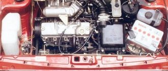
Electrical equipment Oka
After adjustment, tighten the sensor fasteners, turn off the engine, disconnect the strobe light and replace the plug.
Existing types of switches
There are two main types of devices: AC CDI and DC CDI. The first switches were small and simple, using a high-voltage generator in their circuitry. The latter are more common, equipped with four contact groups with minus and plus, as well as separate outputs for the coil and Hall sensor. But the latter function only in the presence of high voltage supplied from an external source.
Switches are also usually classified according to their functional features:
- traditional or stock devices that strictly correspond to the parameters of the car - as a rule, they are installed from the factory;
- sports - they have the ability to increase the upper limit of the number of revolutions of the internal combustion engine, however, this type is the lot of experienced specialists and has the risk of accidents;
- with the ability to adjust the phases of the UZ - an excellent option when you need to equalize the torque of the power plant, improve acceleration characteristics and stabilize engine operation at different speeds.
Of course, switches are usually divided into main types.
Electronic
This type of switch is also called a microprocessor switch with transit keys. It is used to control the converter voltage and reduces the load on the connections, thereby increasing the current capacity.
Advantages of the electronic system:
- possibility of better filling of internal combustion engine cylinders;
- efficient engine output at all speeds.
Hybrid
These systems additionally use a mechanical part - a cam distributor. The electronics are represented by the switch itself and the coil. The unit is very reliable, economical and convenient. For example, if a switch fails, you can switch to an old converter with a slider.
Contactless
A group with transistors, widely used since the early eighties. It replaced the antediluvian classical contact systems. At one time it was considered the most effective, since its performance indicators were much higher than those of other switches.
Dual channel
The same contactless system, but significantly modernized. For example, a conventional BSZ has the same disadvantages of a KSZ - loss of spark energy, instability of idle speed, limitation on adjustment of the SPD, high sensitivity to pollution and humidity. A two-channel system or DBSZ eliminates these disadvantages from the ignition system, providing even higher spark energy through the use of additional coils. Also, problematic moving elements - a slider and a coal - are not used here, and the lid serves only as a protective element. Therefore, it is not subject to burnout.
Interestingly, two-channel ignition was used before. This was implemented on export VAZ-21083. However, switches of this type, also called dual-circuit switches, were not widely used due to the poor quality of the electronics of that time.
One more nuance regarding switches. They may have different outputs. Those with the default number “1” are extremely dangerous for the ignition coils at the moment they experience malfunctions. But the advantage of such devices is that standard converters for contact ignition can be integrated with them.
For the second types of switches, in which output “0” is used by default, conventional coils are completely unsuitable. They will get very hot, or the spark will not flow properly. Such a switch includes, for example, the model for BTsZ 131.3734.