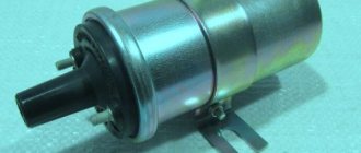
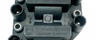
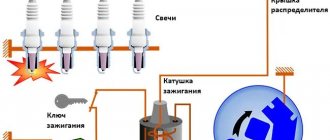
Where does the car begin to move? You can say that it’s from turning the key, or you can say that it’s from “starting” the engine. But to be extremely precise and specific, the answer will definitely be this: it all starts with the ignition coil.
So why does the coil play such an important role? The fact is that this part of the machine starts the process of generating electrical energy, which the engine then converts into mechanical work. Through simple manipulations, the ignition coil transforms low voltage into high voltage. A spark is formed in the spark plug, and its fuse ignites the fuel-air mixture in the combustion chamber. This is how the very energy that sets the pistons in motion is generated.
Ignition coil malfunctions
The main types of ignition coil malfunctions include:
- A short circuit between the turns of any of the windings of the product.
- A break in the electrical circuit of the primary or secondary windings.
- Insulation breakdown of the secondary winding on the body of the device.
- There is a lubricant leak on the product cover.
- Defects on the device cover.
- Incorrect values of the measuring device when measuring the resistance value of the ignition coil of any winding.
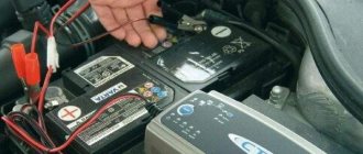
With such above defects, the coil must be replaced. A qualitative check of the ignition coil is divided into several tests. These include:
- testing the product resistance in both circuits;
- testing the resistance of the device to the “mass” of the device.
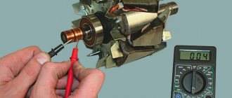
To carry out the test, two conditions must be met: the external temperature must be in the range of 20-25 degrees Celsius and the presence of a measuring device - a megger. We connect the “crocodiles” of the device to the contacts of the product on the right and left and take measurements in the selected range. The winding resistance should be within the range of 0.4-0.5 Ohms. If the measurement value is different, the ignition coil must be replaced with an updated product.
To carry out the test, you need to connect the alligator clips to connector “B” and to the central contact. At the previously determined temperature value of the atmosphere, the measuring device in the given register should show 4.5-5.5 kOhm. If the measurement value of the “nine” ignition coil is different, then the device must be replaced with an updated product.
To test the resistance of the device to ground, one contact is attached to the body of the VAZ 2109 ignition coil, and the other to each output of the product in turn. When taking measurements, the megger must produce a value of at least 50 mOhm in the corresponding register. If the measurement indicator is different, the Lada coil of the ninth model must be replaced with an updated product.
Despite the fact that this “nine” ignition complex is not particularly difficult for a specialist, the principle of its operation is based on the fundamentals of electromagnetic induction and electrical phenomena. This makes it necessary to approach its diagnosis with a certain amount of knowledge in these areas.
In theory, everything turns out quite simply, but a number of car enthusiasts offer an alternative way to increase the functionality of the ignition coil by “nine”. They propose to replace the reel with a product with item number B-117, and replace the set of candles with a set of other products indexed in the number with the same name, but without the letter “P”. These experts assure the excellent reliability of this replacement and report that all the advantages of the contactless ignition system are preserved. The owners of the “nines” will have to make a decision!
Ignition coil
VAZ
2109
. system check
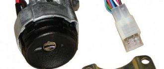
If suddenly the engine starts to stall, the power disappears, or the car won't start at all, the problem most likely lies with the ignition system. If we are talking about a VAZ 2109 carburetor engine, then the ignition system can be corrected even by a beginner. First, you should check the coil
ignition VAZ 2109, trampler, high-voltage wires, etc.
To check the ignition system, you need a multimeter, a Phillips and flathead screwdriver, and pliers with insulated handles. To set the ignition timing, you may need a 12V lamp with socket. To test for spark, you will need one accurately working spark plug, as it is strongly recommended not to test for spark from wire to ground.
When repairing the ignition system on a VAZ 2109, you can get a very unpleasant, but not fatal, electric shock from a high-voltage wire. To prevent this from happening, do not handle high-voltage wires with your bare hands while the ignition is on. For these purposes, it is best to use thick rubber gloves or insulated pliers.
Diagram for switching on direction indicators and hazard warning lights
The direction indicators are activated by the steering column switch. The hazard warning mode (all direction indicators flash) is activated by a switch mounted on the steering column. Since 1995, the design of the switch has changed the connection diagram of the control lamp and eliminated terminals “5” and “6”.
The alarm relay must ensure that the turn signal lamps blink at a frequency of 90±30 per minute at an ambient temperature of –20 to 50° C and a voltage of 10.8 to 15 V. If one of the turn signal lamps burns out, the blinking frequency of the control and remaining lamps doubles.
| The relay is installed in the passenger compartment on the front panel behind the instrument panel. | The diagram for switching on the hazard and turn signals is shown in Figure 2. |
Replacing the side turn signal lamp
If the car has a fender liner, remove it.
| From the inside of the wing, remove the protective cover along with the turn signal socket and replace the faulty lamp. | We insert the cartridge into the pointer body and put on the protective cover. |
Replacing the side turn signal
1. From the inside of the wing, using a “7” head or a piece of pipe of a suitable diameter, we squeeze the antennae of the indicator body clamp and push them into the hole in the wing.
Similarly, push out the second latch and remove the pointer.
We bring the wires out through the hole in the wing.
| 2. To replace the cartridge, remove it from the wires and connect a new one to them. | |
| 3. Insert the lamp with the socket into the pointer housing. | 4. Aligning the clamps with the holes, install the turn signal in place. |
DETAILS: Photo report on changing engine oil in a Volvo XC90 Instructions on how to change engine oil in an XC90
avtomechanic.ru
- Repair manuals
- Repair manual for VAZ 2105 (Zhiguli) 1980-1992.
- Diagram for switching on direction indicators and hazard warning lights
| 1 – block headlights with front direction indicators; 2 – side direction indicators; 3 – mounting block; 4 – ignition relay; 5 – ignition switch; 6 – relay-interrupter for direction indicators and hazard warning lights; 7 – turn signal indicator lamp located in the speedometer; | 8 – rear lights with direction indicator lamps; 9 – alarm switch; 10 – direction indicator switch in a three-lever switch; A – to terminal “30” of the generator; B – numbering of plugs in the hazard warning switch; B – the order of conditional numbering of plugs in the relay-interrupter of direction indicators and hazard warning lights |
Repairing auto parts yourself is a responsible task that should be taken as seriously as possible. Sometimes a faulty spare part takes the driver by surprise, forcing him to spend a lot of time and money searching for a good service station, but there is an alternative solution to the problem; this requires a small amount of knowledge and a set of tools.
When repairing the turn signal and hazard warning circuit of a VAZ 2105 Zhiguli, you need to be extremely careful and not neglect the little things. To get acquainted with the issue, car enthusiasts often use various Internet portals dedicated to auto parts.
Some of them use narrowly focused forums. But, as a rule, only generalized information is provided there, which is known initially. Where can you find a reliable source that offers really useful things? Our portal is open for this 24 hours a day.
A detailed description of such a unit as the circuit for switching on the direction indicators and hazard warning lights of the VAZ 2105 Zhiguli has a good structure with thematic headings. In addition, there is always the opportunity to familiarize yourself with the intricacies of installation. There are often situations when a driver is confident in his abilities, but when he gets down to work, questions begin to arise.
In addition to the repair manual, the owner of a personal car will be able to prevent a lot of breakdowns that occur due to the human factor, thanks to the information located on the site. Users are presented with a lot of useful recommendations for proper operation, which will help significantly extend the life of the unit and avoid many negative consequences.
DETAILS: Renault Logan clutch replacement - MegaSOS
Online support is an excellent and most convenient way to obtain the necessary information. Another significant plus is that articles are written for people. We understand that the reader will do everything with his own hands, and we try to make it as convenient and efficient as possible. Use the resource at any time of the day and find the answer to any question you may have regarding cars.
July 13th, 2013 admin
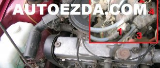
Distributor slider VAZ 2109
Removal and installation
If the distributor fails, it can be repaired or replaced with a new one. It all depends on the specific failure.
The removal and installation procedure is as follows:
First you need to de-energize the car's electrical circuit by disconnecting the battery. Then you need to disconnect the wires from the switchgear. After this, also disconnect the vacuum tube going to the corrector. Next you need to find the cable holder that goes to the throttle actuator. This cable must be removed. Remove the bracket holding the wires, along with them and the pins. To do this you will need to unscrew the nut. Be careful. There is a washer under the nut, you can't lose it. After this, you need to mark the switchgear housing and the drive of the auxiliary elements. If you do not put a mark, then after further securing the mechanism in place you will have to reinstall and adjust the ignition. On the distributor body there is a socket to which the high-voltage wire harness is connected. The fasteners need to be compressed; to do this, remove the wires using a screwdriver. Then remove the rubber plug that is located in the clutch housing. Rotate the crankshaft by hand until the piston of the 1st cylinder reaches TDC. The mark on the flywheel in the hole should correspond to the center line on the housing scale. You can then unscrew the nuts that secure the manifold and remove it. As for further installation, it is carried out in the reverse order. When reinstalling the device, make sure that the valve shaft rotates so that the outer contact of the slide is opposite the terminal corresponding to cylinder 1 of the internal combustion engine. The terminal itself is located on the lid. During installation, combine the risks as we reported above. If you have difficulty installing the ignition, use this article.
Sorry, there are no surveys available at this time.
Purpose of distributor VAZ 2109
In any ignition system, contactless or contact, there are two circuits. high voltage and low voltage. Distributor, ignition distributor. It is a device that deals with both high voltage wiring and low voltage wiring. His main task. distribute high voltage between the spark plugs at the right time and in a certain order.
The distributor works as follows. High voltage is created in the ignition coil due to electromagnetic induction. It is connected via a high-voltage wire to the central contact of the distributor cap. The contact is in constant interaction with the slider, which distributes the current to four contacts corresponding to the spark plug in the cylinder. The slider constantly rotates and alternately closes the central contact with the spark plug contacts. Current is supplied to the spark plugs through high-voltage wires in the order determined by the cylinder sequence. 1-3-4-2. The slider is driven by a drive shaft, which is connected to the camshaft.
Tuning on carburetor modifications of the VAZ 2107
All old textbooks on servicing classic Zhiguli models describe a method for setting the moment of spark formation using a light bulb, although experienced motorists can easily do without it. You will understand why this happens as you read this material, but for beginners it will be useful to familiarize yourself with the old proven technique.
To correctly set the ignition of the “seven”, you need to ensure that the following conditions are met simultaneously:
- the notch on the crankshaft pulley is opposite the long mark on the timing cover;
- in this case, the round mark marked on the camshaft chain drive gear coincides with the boss on its body;
- the piston of the 4th cylinder has completed the compression stroke and is at top dead center; the contacts inside the distributor are open;
- The movable contact of the slider faces the fixed contact on the distributor cover, where the wire from the spark plug of the 4th cylinder is connected.
Note. On non-contact systems, at this moment the Hall sensor sends a signal to the switch to break the low voltage electrical circuit, which leads to the appearance of a high voltage pulse on the wire leading to the spark plug of the 4th cylinder.
The diagram shows what happens in the cylinders when the marks are aligned
The light bulb is used to control the ignition timing, for which it must be connected with one wire to the “K” contact of the high-voltage coil, and with the second to the vehicle ground. You should know that at the same moment the piston of the first cylinder is also in the TDC position, only there the air-fuel mixture is not compressed, but exhaust gases are released after its combustion. This is why ignorant car enthusiasts often confuse the first cylinder with the fourth when installing the ignition.
Layout of marks on the timing cover
When the above actions occur simultaneously, a spark discharge occurs on the electrodes of the spark plug of the 4th cylinder, as evidenced by the flash of the connected light bulb. To achieve these conditions and set the ignition correctly, follow the instructions:
- Turn the crankshaft with a 36 mm wrench, aligning the notch on the pulley with the long notch on the timing cover.
- If at this moment the engine valve cover is removed, then it is better to navigate by the mark on the camshaft gear, placing it opposite the housing boss.
- Take the ignition distributor, remove the cover and turn its shaft to place the slider opposite the wire leading to cylinder No. 4 (there are cylinder number markings on the cover). Insert the distributor into the engine hole, holding the slider and housing in this position, and then secure it with a 13 mm wrench nut.
- Connect the light bulb wires and turn on the ignition by turning the key. Loosen the nut securing the distributor and slowly turn it by the housing until the lamp flashes, indicating the moment of sparking. Reattach the distributor.
- Turn off the ignition and make sure that the contacts inside the distributor are currently open. Take a 0.35 mm feeler gauge and check the gap between them, if necessary, adjust it by loosening the fastening screws with a screwdriver.
The marks must be aligned by turning the crankshaft with a wrench
Note. The instructions imply that before starting work the distributor was removed from the engine without aligning the marks.
The ignition is considered to be set correctly if, after installing the distributor cap and connecting the wires, you manage to start the engine, and then you need to adjust the timing. The non-contact system is installed in the same way, with the exception of checking the gap in the contact group due to its absence.
The mark on the camshaft gear is aligned with the boss on the body
Important point. In most cases, the ignition is set without removing the valve cover, which is why the position of the mark on the gear is not visible. You have done everything according to the instructions, but the engine does not start. This means that a spark is supplied to the 4th cylinder during the exhaust stroke, and compression at this moment occurs in the first cylinder. The problem can be solved simply:
- remove the distributor cover;
- unscrew the nut securing it;
- pull the distributor out of the socket, turn the slider exactly 180° and insert the element back;
- Press the distributor skirt with the nut and install the cover.
Advice. If the engine does not start after these steps, but begins to show signs of life, then the problem lies not in the ignition setting, but in a malfunction of one of the system elements.
Features of the operation of different ignition systems
Ignition on the VAZ 2109 is necessary to ignite the air-fuel mixture when starting the engine. If the ignition does not work correctly, the engine will start and run intermittently, and its power during start-up and acceleration will noticeably decrease. In addition, fuel consumption will be noticeably increased. The conclusion from this is that the correct operation of the ignition system should be constantly monitored.
It’s worth mentioning right away the differences in the ignition design of “nines” with different types of fuel supply. Their SZ is similar, but they differ in the elements of electric charge distribution.
- In “nines” equipped with a carburetor, there is a coil and a distributor.
- For systems with an injector, an ignition distribution module consisting of several coils and an electronic controller is installed.
The second difference is how the system works. In cars with an injector it is not required, but in VAZs with a carburetor you have to do it manually.
In nines, two types of ignition systems are used:
- contact;
- contactless with transistors.
The first is installed in carburetor “nines”, and the second in injection ones. Thanks to the use of contactless ignition, the system has the following advantages:
- Working with a Hall sensor, which makes the system more stable and increases its overall efficiency.
- The absence of contact with the working parts and elements of the system increases the service life of the elements and makes maintenance of the circuit components easier.
- Excellent spark distribution between spark plugs.
- Generating a powerful spark, which prevents system failures.
- Fuel economy.
- Works even with low battery charge.
Over time, the contact type SZ has practically ceased to be used, so from now on we will focus on the contactless analogue.
Starter problems
Many VAZ 2110 owners had a situation where the starter did not turn after inserting and turning the key. They heard characteristic clicks. This indicates that the solenoid relay is not working.
What to do in this situation? Some will say that you need to determine where the ignition relay is located on the VAZ 2110 and solve the problem.
But the fact is that the “ten” does not have a starter relay, that is, an ignition relay as such. Instead, a solenoid relay works. It is supplied with a positive contact from the ignition switch. Mount this relay to the starter. It has a round shape and is approximately half the size of the starter itself.
Ignition coil malfunctions
The main types of ignition coil malfunctions include:
- A short circuit between the turns of any of the windings of the product.
- A break in the electrical circuit of the primary or secondary windings.
- Insulation breakdown of the secondary winding on the body of the device.
- There is a lubricant leak on the product cover.
- Defects on the device cover.
- Incorrect values of the measuring device when measuring the resistance value of the ignition coil of any winding.
With such above defects, the coil must be replaced. A qualitative check of the ignition coil is divided into several tests. These include:
- testing the product resistance in both circuits;
- testing the resistance of the device to the “mass” of the device.
To carry out the test, two conditions must be met: the external temperature must be in the range of 20-25 degrees Celsius and the presence of a measuring device - a megger. We connect the “crocodiles” of the device to the contacts of the product on the right and left and take measurements in the selected range. The winding resistance should be within the range of 0.4-0.5 Ohms. If the measurement value is different, the ignition coil must be replaced with an updated product. To carry out the test, you need to connect the alligator clips to connector “B” and to the central contact. At the previously determined temperature value of the atmosphere, the measuring device in the given register should show 4.5-5.5 kOhm. If the measurement value of the “nine” ignition coil is different, then the device must be replaced with an updated product. To test the resistance of the device to ground, one contact is attached to the body of the VAZ 2109 ignition coil, and the other to each output of the product in turn. When taking measurements, the megger must produce a value of at least 50 mOhm in the corresponding register. If the measurement indicator is different, the Lada coil of the ninth model must be replaced with an updated product.
Despite the fact that this “nine” ignition complex is not particularly difficult for a specialist, the principle of its operation is based on the fundamentals of electromagnetic induction and electrical phenomena. This makes it necessary to approach its diagnosis with a certain amount of knowledge in these areas. In theory, everything turns out quite simply, but a number of car enthusiasts offer an alternative way to increase the functionality of the ignition coil by “nine”. They propose to replace the reel with a product with item number B-117, and replace the set of candles with a set of other products indexed in the number with the same name, but without the letter “P”. These experts assure the excellent reliability of this replacement and report that all the advantages of the contactless ignition system are preserved. The owners of the “nines” will have to make a decision!
When should you change the ignition coil? • The coil must be replaced if various types of defects appear on the ignition coil itself, namely on its plastic part: 1. Cracks. 2. Skolov. 3. And also signs of overheating. 4. And traces of oil leaks.
How to set the ignition?
Be sure to check the lead angle. This is done only when the engine is idling at a crankshaft speed of 820-900 rpm.
It’s not difficult to figure out how to set the ignition on a VAZ 2110.
- The angle should be between 0 plus or minus 1 degree to top dead center.
- If the angle is set incorrectly, the engine will overheat, but will not be able to produce full power, and fuel consumption will increase. The possibility of detonation cannot be ruled out.
- The ignition timing is checked by the mark on the flywheel and the scale on the clutch housing hatch.
- The plug must be in the extended position.
- Pistons from cylinders 1 and 4, when combining the marks (on the flywheel) and the middle mark (on the scale), are installed at top dead center.
- One division on the scale equals exactly 1 degree of crankshaft rotation.
Checking the coil for VAZ 2101-2110
First, let's look at the sequence of checks on VAZ cars. Moreover, checking the carburetor for VAZ-2101 and VAZ-2110 is no different, the only difference is in the readings.
Next is the verification process itself:
It is better to test the coil when it is removed from the car. Before starting removal, disconnect the negative terminal from the battery. From the coil we disconnect the wires from the side terminals, as well as the central wire. It is better to mark the wires from the side terminals so that they are not confused during installation. Loosen the coil fastening and remove it
Before checking with a multimeter, we clean it from dust and dirt, especially paying attention to the terminals. Then we inspect it for external damage.
If there are any, further checking is pointless; it is better to replace it immediately; Checking the primary winding. To do this, switch the multimeter to ohmmeter mode and connect its probes to the side terminals. Different types of coils were used on different VAZ models, so you need to know which resistance readings are correct for them. So, for the B-117A model, used on classical models (VAZ-2101-2107), the resistance of the primary winding is 3.07-3.5 Ohms. And on classic models with a contactless system, coils marked 27.3705 are used; this parameter is 0.4-0.5 Ohm. On VAZ-2108-21099 cars, as well as VAZ-2110 carburetor, models with numbers are used - 3122.3705 and 8352.12. For the first of them, the resistance of the primary winding is considered normal in the range of 0.39-0.47 Ohms, and for the second - 0.37-047 Ohms; Next, the secondary winding is checked. To do this, switch the multimeter to the kOhm measurement mode, leave one of its probes on the side terminal, and connect the second to the central terminal. For a working B-117A coil, the resistance of the secondary winding should be 7.4-9.2 kOhm. For model 27.3705 this parameter should be around 5.0 kOhm, for 3122.3705 - 0.4 kOhm, and for 8352.12 - 1.0 kOhm; The last thing to check is the insulation resistance. To measure this parameter, switch the multimeter to measurement mode in MOhm. To measure, we connect one probe to the coil body, and connect the second to each terminal in turn. When measuring this parameter on all specified models, the multimeter should show at least 50 MOhm; If any of the parameters does not match the specified values, then the coil is faulty and must be replaced.
Tuning on carburetor modifications of the VAZ 2107
All old textbooks on servicing classic Zhiguli models describe a method for setting the moment of spark formation using a light bulb, although experienced motorists can easily do without it. You will understand why this happens as you read this material, but for beginners it will be useful to familiarize yourself with the old proven technique.
To correctly set the ignition of the “seven”, you need to ensure that the following conditions are met simultaneously:
- the notch on the crankshaft pulley is opposite the long mark on the timing cover;
- in this case, the round mark marked on the camshaft chain drive gear coincides with the boss on its body;
- the piston of the 4th cylinder has completed the compression stroke and is at top dead center;
- the contacts inside the distributor are open;
- The movable contact of the slider faces the fixed contact on the distributor cover, where the wire from the spark plug of the 4th cylinder is connected.
The diagram shows what happens in the cylinders when the marks are aligned
The light bulb is used to control the ignition timing, for which it must be connected with one wire to the “K” contact of the high-voltage coil, and with the second to the vehicle ground. You should know that at the same moment the piston of the first cylinder is also in the TDC position, only there the air-fuel mixture is not compressed, but exhaust gases are released after its combustion. This is why ignorant car enthusiasts often confuse the first cylinder with the fourth when installing the ignition.
Layout of marks on the timing cover
When the above actions occur simultaneously, a spark discharge occurs on the electrodes of the spark plug of the 4th cylinder, as evidenced by the flash of the connected light bulb. To achieve these conditions and set the ignition correctly, follow the instructions:
- Turn the crankshaft with a 36 mm wrench, aligning the notch on the pulley with the long notch on the timing cover.
- If at this moment the engine valve cover is removed, then it is better to navigate by the mark on the camshaft gear, placing it opposite the housing boss.
- Take the ignition distributor, remove the cover and turn its shaft to place the slider opposite the wire leading to cylinder No. 4 (there are cylinder number markings on the cover). Insert the distributor into the engine hole, holding the slider and housing in this position, and then secure it with a 13 mm wrench nut.
- Connect the light bulb wires and turn on the ignition by turning the key. Loosen the nut securing the distributor and slowly turn it by the housing until the lamp flashes, indicating the moment of sparking. Reattach the distributor.
- Turn off the ignition and make sure that the contacts inside the distributor are currently open. Take a 0.35 mm feeler gauge and check the gap between them, if necessary, adjust it by loosening the fastening screws with a screwdriver.
The marks must be aligned by turning the crankshaft with a wrench
The ignition is considered to be set correctly if, after installing the distributor cap and connecting the wires, you manage to start the engine, and then you need to adjust the timing. The non-contact system is installed in the same way, with the exception of checking the gap in the contact group due to its absence.
The mark on the camshaft gear is aligned with the boss on the body
Important point. In most cases, the ignition is set without removing the valve cover, which is why the position of the mark on the gear is not visible. You have done everything according to the instructions, but the engine does not start. This means that a spark is supplied to the 4th cylinder during the exhaust stroke, and compression at this moment occurs in the first cylinder. The problem can be solved simply:
- remove the distributor cover;
- unscrew the nut securing it;
- pull the distributor out of the socket, turn the slider exactly 180° and insert the element back;
- Press the distributor skirt with the nut and install the cover.
THE MOST KNOWN PROBLEMS WITH IGNITION COIL BREAKAGE:
- Winding damage. This factor leads to breakdown of the insulating layer, resulting in a short circuit.
- Open circuits and overload. The reason is a malfunction of the spark plugs or due to defects in high-voltage wires.
In general, ignition coils fail quite rarely, but sometimes such troubles do happen. Typically, the insulating layer of the coil can be damaged as a result of an instantaneous voltage increase of up to 35,000 V. As a result, the secondary voltage drops and misfires occur under load. As a result, the coil cannot produce the voltage needed to start the engine running.
Reasons for failure of ignition coils:
— Spark plugs are of low quality. Always monitor the quality of the spark plugs installed on your car and do not install cheap fakes - if you skimp on this, you can end up getting stuck for a much tidy sum. The reason is reverse gases and insulator breakdown, which adversely affect the condition of the rubber tip of the ignition coil.
— Overheating of the ignition coils. Structurally, the coils are designed to work at any temperature conditions of the engine, but as practice has shown, if your engine is hotter than it should be (lean mixture, faulty cooling system), the coils “die” more actively. We do not want to say that any heating is fraught with danger to the coil, but there is a certain resource for heating-cooling cycles. This also affects the rubber tip and the electronics of the reel.
What are the risks of driving with a non-working coil:
— Melting of the catalytic converter in the exhaust system.
— If you drive with a faulty coil, the engine mounts may wear out over time due to excessive vibrations.
— High fuel consumption associated with a drop in engine power and efficiency.
How to check a non-working coil yourself:
— The easiest way is to alternately disconnect the connectors (chips) from each coil in turn during “triplication”, so when you disconnect a chip from a working coil, you will hear a dip in revolutions and unstable operation on the remaining cylinders, and when disconnected from a non-working coil, the engine will run Will not change. It is this coil that needs to be changed.
— If it is possible to remove the coils, then a good way to determine this is to measure the resistance of the primary and secondary windings (between the contacts, between the contacts and the output to the spark plug), record and compare the readings on all coils, usually the resistance of faulty coils is strikingly different
In addition, pay attention to the condition of the spark plug electrodes; on a faulty coil, the spark plugs are usually wet and with black soot
- In some cases, the car’s self-diagnosis can “tell” which cylinder is not igniting (only if the check engine light is on). Look for trouble codes for your car.
How professionals determine a faulty ignition coil:
There are motor testers (scanners) that allow you to analyze the operation of electronic components of cars, including coils. The author of the article came across three different methods for professionally identifying a faulty coil: alternately turning off the cylinders (turning off the injectors), alternately turning off the control voltage, and analyzing the curves of an oscilloscope connected to the coils.
Professional diagnosticians NEVER DISCONNECT THE COILS MANUALLY, as this can lead to failure of the engine ECU.
What to do with a non-working coil???
The most reasonable way is to replace it, all imported ignition coils are non-separable and filled with polymer to prevent moisture from entering, even if you can replace/repair microelectronic parts, it is no longer possible to assemble the coil without oxygen getting inside. Replacing the ignition coil - only in this case can you ensure long-term operation of your car!
If the manufacturer of your car has provided for the supply of a separate rubber tip from the ignition coil, you can order and replace the old tip with a new one, but this will not guarantee you that the electronic part that worked under increased load has survived in the old coil.
VAZ 2105 ignition settings - about the Zhiguli 2105 “Five” on RusAuto.org
VAZ 2105 ignition settings Hello! engine 2105. gasoline 92. I put a mark on the crankshaft on the longest line (lowest). I connect a voltmeter to the coil wire and to ground. I twist the distributor so that the voltmeter shows 12+, then I move it until the voltmeter shows no voltage (spark moment). I tighten the distributor nut. The car drives fine... no real complaints. but I read somewhere that at straight speed (mine is 4th) with the throttle fully opened at 60 km per hour there should be detonation for about 2 seconds. What kind of detonation is this and I don’t understand how to hear it? listened to it more than once. nothing clicks or anything. the car just accelerates. without obvious afterburner effect. well, roughly speaking, it doesn’t howl and start driving like a sports car. It just accelerates quickly. there's a long road ahead this week
please advise what to do... leave it like this? Or should I still make fine adjustments? or there is an option to take it to a station and set it up with a strobe light for $2. thank you for your attention
The detonation is similar in sound to the tapping of fingers. Sounding metallic knock
Stasyan Why are you worrying if everything is normal? When it starts to detonate, you will understand. Gillard Look here: https://vazik. ru/plugins/content/content… Taras There should be no detonation on a normally adjusted engine! Alevtina, don’t read too many books... if it’s driving, then everything is fine. Natuliodetonation is the ignition of the fuel much earlier than TDC. this can happen because the ignition is too early or the gasoline is of poor quality and ignites from compression much earlier than expected (before the spark) or the wrong gasoline is poured (with a lower octane number) by the way, when “fingers knock” this is detonation (in fact fingers never knock faster than the shaft knocks) we hear this premature explosion of fuel. on a tuned engine, when driving on a flat area, in direct gear, about 60-70 km/h, give full throttle and you will hear detonation (your fingers will start tapping and then stop), this is normal. How to remove the starter on a VAZ 21072? instructions for the kettle are needed There is no power from the ignition switch to the starter. What could be the reason? VAZ-21072VAZ 11193 "KALINA". The battery died and after replacement it will not start. no indica ENGINE, the starter does not turn, the fuses are intact, how to open the hood if the cable has come off on a VAZ 11193 (Kalina) please help VAZ 1119 Kalina engine 1, 4 16V if the timing belt breaks, does it bend the valves?
rusauto.org
Examination
If you notice signs of a problem with the ignition coil, or have to deal with a situation where the engine “died,” be sure to check the condition of this element.
As you test, you will be able to determine what caused the coil to fail and how the problems can be corrected.
https://youtube.com/watch?v=Z5cUQhKBZm0
Ignition coil
How to check the device? The instructions are not complicated, even a beginner can handle it.
First, let's check the condition of the unit, and then check for correctness of the resistance of the coil itself.
- If the engine cannot be started, make sure that the coil itself is producing a spark at all. To do this, the central wire is removed from the distributor and a spare spark plug is connected to it.
- Now take the spark plug with pliers and place the metal casing on the breaker or motor.
- If a spark does not appear when the engine starter is turned, there is a malfunction in the ignition system.
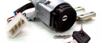
- So check the power to the coil, or rather its presence. For this you will need a multimeter. One terminal is connected to contact B on the coil, and the second goes to ground. Turn on the ignition. If there is no voltage, the culprit is the ignition switch.
- You can start the engine in emergency mode. To do this, the plus from the battery is thrown onto contact B of the coil.
If there is voltage but there is no spark, check whether the primary winding is intact. To do this, the side low-voltage wires are disconnected from the coil and resistance measurements are taken with a multimeter. Then the secondary winding is checked.
ignition coil
We will tell you about this procedure in more detail.
Multimeter for testing
Checking coil resistance
- Unplug your car. To do this, simply disconnect the negative terminal from the battery.
- Disconnect all wires and leads going to and from the coil.
- Be sure to arm yourself with the necessary tools and a tester. A universal multimeter or ohmmeter will work fine.
- Take measurements on the primary winding. To do this, the tester probes must be connected to the low-voltage terminals located at the edges of the coil. Before doing this, do not forget to clean the terminals from accumulated dirt and traces of oxidation. Surely they formed during the operation of the car.
- Record the data.
- Now the resistance of the secondary winding is checked. To do this, you need to transfer one ohmmeter probe to terminal B of the coil, and the second to the high voltage.
- Note your results.
- The last stage of the test involves measuring the insulation resistance to ground. To do this, you need to connect one terminal of your tester to ground (this is the ignition coil housing), and connect the second one in turn to all three terminals - a pair of low-voltage terminals and one high-voltage one located in the middle of the device. If the coil is working properly, then in all three measurement cases you will get a resistance of at least 50 ohms.
- Check the table against the previously recorded data.
[media= https://www.youtube.com/watch?v=2F4BDExybgs]
| Coil type | Winding | Resistance indicators |
| 3122.3705 | Primary winding | 0.43 ohms +/- 0.04 ohms |
| 8352.12 | 0.42 ohm +/- 0.05 ohm | |
| 3122.3705 | Secondary winding | 4.08 ohms +/- 0.40 ohms |
| 8352.12 | 5.00 ohms +/- 1.00 ohms |
We measure the resistance of the ignition coil
Repair
In fact, the only way to repair a faulty ignition coil on a carburetor or injection VAZ 2109 is to replace the device.
Here you just need to choose which element will replace your old coil.
- MZATE-2. This is a standard coil, which all VAZ 2109s were equipped with from the factory. It costs about 600 rubles and serves well;
- An excellent alternative option, characterized by reliability, durability and operational efficiency. But it costs about 1800-2000 rubles;
- Valeo. Something between the factory and Bosch version, which has good characteristics and positive reviews. Today such a reel costs an average of 1,500 rubles.
The coil is the most important element of the ignition system; if it fails, you can forget about traveling about your business.
How to check an ignition coil: 3 proven methods
Loading …
Step-by-step instruction
Turn the crankshaft with a wrench and align the mark on its pulley with the long mark on the block.
If the valve cover is removed, you need to follow the mark on the camshaft gear. Then remove the cover from the distributor and turn its shaft so that the slider is opposite the fourth cylinder. Next, the distributor is inserted into the engine, holding the slider, and the distributor is securely fixed with a nut.
Connect the wires and turn on the ignition. The nut is released and the distributor is slowly turned by its body. When the lamp flashes, the distributor is secured in this position. It is better to turn off the ignition to make sure that the contacts in the distributor are open. You can check the gap between them using a feeler gauge.
This way you can set the ignition on a VAZ-2105, but this is only the initial setting. For stable operation of the engine, the OZ will need to be adjusted.
Checking the ignition coil on VAZ 2108, 2109, 21099 cars
If such malfunctions occur in the operation of the engine of VAZ 2108, 2109, 21099 cars such as the disappearance of a spark or a weak spark, unstable idling, inability to adjust idle speed, difficult starting or impossibility of starting the engine, failures and jerks when starting and in motion, etc., It makes sense to check the functionality of the ignition coil.
Required Tools
- 8 mm spanner or open-end wrench
— a tester (multimeter or similar device) with an ohmmeter mode (preferably also a megohmmeter)
Preparatory work
You can check the ignition coil on VAZ 2108, 2109, 21099 cars without removing it from the car.
- remove the negative terminal from the battery
- disconnect the high-voltage wire from the ignition coil
- disconnect the wires leading to the two terminals of the coil
To do this, use an 8 mm wrench to unscrew the nuts securing the wires to terminals “K” and “B”. We disconnect the wires, remembering their position, so as not to confuse them when installing them back.
— Check the serviceability of the primary winding of the ignition coil
Checking the primary winding of the ignition coil of VAZ 2108, 2109, 21099 To do this, connect one tester probe to terminal “B” and the second probe to terminal “K” - the terminal of the primary winding. We turn on the device in ohmmeter mode. The resistance of a serviceable primary winding of the ignition coil should be close to zero (0.4 - 0.5 Ohm). If it is lower, then there is a short circuit, if higher, there is a “break” in the winding.
— Check the serviceability of the secondary (high-voltage) winding of the ignition coil
Checking the secondary winding of the ignition coil of VAZ 2108, 2109, 21099 To do this, connect one tester probe to terminal “B” of the ignition coil, and the second probe to the terminal for the high-voltage wire. We measure resistance. For a working secondary winding it should be 4.5 - 5.5 kOhm.
— Check the insulation resistance to ground
For such a test, it is necessary that the multimeter has a megohmmeter mode (or a separate megohmmeter is needed) and can measure significant resistance.
To do this, we attach one tester probe to terminal “B” of the ignition coil, and press the second probe to its body. The insulation resistance must be very high - 50 mOhm or higher.
If at least one of the three checks shows a malfunction, the ignition coil should be replaced.
Notes and additions
— Ignition coils installed on VAZ 2108, 2109, 21099 cars can be of two types: dry with a closed magnetic circuit (3122.3705) and oil-filled with an open magnetic circuit (8352.12, 027.3705, 27.3705, 27.3707-01, ATE1721). The winding resistances for them are slightly different. Coil 3122.3705 – primary winding 0.43±0.04 Ohm, secondary 4.08±0.4 kOhm. Coils 8352.15, etc. – primary winding 0.42±0.05 Ohm, secondary 5±1 kOhm. Measurements were carried out at +25 degrees.
Twokarburators VK - More information on the topic in our VKontakte group, on Facebook Twokarburators FS, in Odnoklassniki - Twokarburators OK and in Yandex Zen - Twokarburators DZ
— The procedure for connecting high-voltage wires to the distributor cover on VAZ 2108, 2109, 21099 cars
— Malfunctions of the contactless ignition system of VAZ 2108, 2109, 21099 cars
— Malfunctions of the distributor of VAZ 2108, 2109, 21099 cars
— Checking high-voltage wires on VAZ 2108, 2109, 21099 cars
— Setting the ignition timing on the engines of VAZ 2108, 2109, 21099 cars
Comparative test repair
— Checking the ignition coil of the ignition system of carburetor engines of VAZ 2101, 2102, 2103, 2104, 2105, 2106, 2107 cars
BB wires
High-voltage wires (HV wires) of the ignition system are designed to transmit high-voltage pulses from the ignition coil to the spark plugs. Structurally, such a cable is a metal central conductor covered with a layer of insulation made of PVC, rubber or polyethylene, as well as a special layer that increases the resistance of the wire to chemical influences (fuel, oil). Today, silicone explosive wires, which are characterized by high elasticity at low temperatures, have become widespread. Such cables work great in wet weather and do not overheat.
Spark plug wires provide connection to the ignition coil, distributor and spark plugs
Malfunctions
The occurrence of problems with spark plug wires manifests itself in the form of unstable operation of the power unit:
- problematic engine starting, especially in wet weather;
- interruptions in the operation of the power plant at medium and high speeds;
- if the central conductor is damaged, the motor stalls;
- power decreases;
- fuel consumption increases.
Problems with high-voltage wires arise mainly due to aging. Over time, the insulating layer becomes covered with small cracks, which is caused by temperature changes in the engine compartment. As a result, a current leak appears through the damaged areas: a spark breaks through to ground and there is not enough electricity for normal sparking. When dirt accumulates on the surface of wires and protective caps, the surface conductivity of the insulation increases, which leads to current leakage. In addition, leakage is also possible due to oxidation of the cable contacts, when the tightness of the protective cap is broken, for example, if it is damaged.
One of the malfunctions of high-voltage wires is a break
How to check
Before proceeding with a more detailed diagnosis of explosive wires, you need to inspect them for damage, such as cracks, fractures, tears in protective caps, etc. After this, you can resort to one of the following methods:
- Use a known-good cable. To do this, we disconnect the explosive wires one by one, replacing them with a spare one. If stable operation of the motor resumes, this will indicate a damaged element.
- Wait until dark. When darkness comes, open the hood and start the engine. In the event of a cable breakdown, a spark will be clearly visible on the faulty element.
- Use an additional wire. To do this, we use an insulated piece of cable, stripping both ends. We connect one of them to ground, and run the second one along the spark plug wire, especially in the places of bends and caps. If a high-voltage cable breaks through, a spark will appear in the problem area between the additional wire.
- Diagnostics with a multimeter. Using the device, we determine the resistance of the cables by selecting the ohmmeter mode. Having disconnected the wires from the ignition coil and distributor, we measure the resistance one by one. A working wire should have a reading of about 5 kOhm. If the central core is broken, the values will be missing.
If any kind of malfunction is detected with the spark plug wires, it is necessary to replace them, and not only the problematic cable, but the entire set.
Video: diagnostics of high-voltage wires
Which ones to put
The choice of explosive wires is a responsible undertaking, since they directly affect the performance of the power plant, and a high price is not always an indicator of quality. It is best to give preference to spark plug wires with a copper central core. The resistance should be about 4 kOhm. Wires with zero resistance lead to rapid burnout of the central electrode of the spark plug and its premature failure. When choosing, you should pay attention to the following manufacturers:
- BERU;
- NGK;
- PARTS-MALL;
- AMD;
- Bremi;
- Tesla Technics.
Today a large selection of spark plug wires is offered, but it is better to give preference to well-known manufacturers
labavto.com
One of the reasons for problems with a spark in the internal combustion engine on a VAZ 2109 is a malfunction of the ignition coil (IC). To accurately diagnose a malfunction, you need to know the design of the unit, be able to check it and, if necessary, install a new product.
Coil design features
This unit is designed to convert low on-board voltage (12 V) into high voltage (15-30 thousand V), which is supplied to the spark plugs to ignite the fuel assemblies in the engine cylinders. The impulse is transmitted through high voltage wires.
Both engines with injector and carburetor engines have an ignition system with a distributor (distributor). The scheme of work is not complicated. The distributor receives low-voltage current, which is then transmitted to the short circuit. The received pulse is converted into high-voltage current. Then the distributor distributes it in a certain order to the candles.
The main elements of the coil are the primary and secondary windings, wound on an external magnetic circuit. The first one has a small number of turns of copper wire - from 100 to 150, but it has a large cross-section. The second has a much larger number of turns - from 15,000 to 30,000, the wires are also made of copper, but with a smaller cross-section. There is a primary winding on top, and a secondary winding inside it.
In the secondary winding, a high-voltage current arises due to the action of electromagnetic induction and the accumulation of charge in the primary winding, which arise after cutting off the current in the primary. The high-voltage current is supplied to the central terminal of the short circuit, and then the distributor distributes it to the spark plugs.
Signs and causes of malfunctions
Most often, the spark disappears unexpectedly, but attentive drivers with experience can predict the disappearance of the spark by the following signs:
- 500 km before the end of the short circuit service life, the car can sometimes be difficult to start, only after a few minutes of warming up. Some drivers associate this with idling.
- When starting a cold engine and pressing the accelerator pedal, the engine begins to actively rev. This lasts a few seconds and after further pressing the accelerator, the engine runs normally.
- Dips or jerks at start.
- Unstable idling, unstable engine operation at low speeds.
- When you press the accelerator hard, instead of increasing speed, dips appear.
- Weak spark or its complete disappearance.
Typical short circuit faults:
- there are oil stains on the cover;
- short circuit between the turns of any of the windings;
- breakdown of insulation of the secondary winding to the housing (ground) short circuit;
- break in the electrical circuit of the windings;
- mechanical damage or defects on the body or cover of the short circuit;
- The readings on the measuring tester do not meet the requirements.
Contactless distributor
The contactless ignition system is a modernized KSZ. Its main difference is the absence of a contact group, instead of which a Hall sensor is used. The advantages of such a distributor are:
- no need for periodic adjustment;
- more reliable engine starting;
- reduction in fuel consumption;
- increase in power.
A non-contact distributor is considered a more modern and reliable device
The Hall sensor is mounted on the distributor shaft. Structurally, it consists of a permanent magnet, which has a special screen with slots. The number of slots usually corresponds to the number of cylinders. As the shaft rotates, the screen holes pass past the magnet, causing changes in its field. During operation of the ignition distributor, the sensor reads the shaft revolutions, and the received data is fed to a switch, through which the signal is converted into current.
Examination
Checking the contactless mechanism repeats the same steps as with the contact system, excluding the contact group. In addition to the cover and slider, problems may arise with the switch. The main sign indicating problems with it is the absence of a spark on the candles. Sometimes a spark may be present, but very weak or disappear periodically. At the same time, the engine runs intermittently, stalls at idle, and power decreases. The same problems can occur if the Hall sensor malfunctions.
Switch
The easiest way to test a switch is to replace it with a known good one. Since this possibility is not always available, another diagnostic option is also possible.
One of the reasons for the lack of spark on the spark plugs may be a faulty switch
Before starting the test, you must make sure that power is supplied to the ignition coil and that the Hall sensor is in working condition. The tools you will need are a test lamp and a standard set of keys. We check the switch in the following sequence:
- Turn off the ignition.
- Unscrew the nut on the coil contact “K” and disconnect the brown wire.
- We connect the control unit into the gap between the removed wire and the coil contact.
- Turn on the ignition and crank the starter. The light indicator will indicate that the switch is working properly. If there is no light, the switch will need to be replaced.
Video: checking the ignition distributor switch
To replace the switching device, simply unscrew the mount to the body, disconnect the connector and replace the non-working part with a working one.
Hall Sensor
The sensor is located inside the distributor, so to access it you will have to remove the cover.
The Hall sensor does not fail very often, and if this happens, the fault can be identified by the absence of a spark
You can check the part in several ways:
- replace the sensor with a known good one;
- use a multimeter to check the voltage at the output of the element, which should be 0.4–11 V;
You can check the Hall sensor with a multimeter by connecting the device to the output of the device - assemble a circuit that simulates the operation of the sensor by connecting contacts 3 and 6 going to the device being diagnosed (the appearance of a spark will indicate a faulty part).
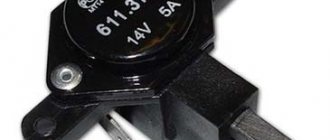
Kalina, 1117-1119
A more modern VAZ model, Lada Kalina, is equipped with an ignition module marked: 2112-3705010-12. It has the following characteristics:
Load voltage 1MΩ +25pF>24kV
Spark charge duration 1.14-1.5 ms
Operating temperature range from -40 to +140 degrees C
Rated supply voltage 12V.
How to check the malfunction of the VAZ 2114 ignition module on your own?
The easiest way to check the device without removing it is to diagnose it at the moment the power unit is tripped. When the motor begins to operate unstably, it is necessary to disconnect the connector elements from each component of the module one by one. If the connector is disconnected from a functioning device, the operation of the engine will change. Dips will appear, and the unstable operation of the unit will increase. When the non-working element of the MH is disconnected, the motor will operate in the same way.
There is another simple diagnostic method, its principle is as follows:
- You will need an assistant to check. The spark plug is removed from the seat. The high-voltage cable is disconnected from the device.
- Then the disconnected wire is connected to a spark plug, which is applied to the body of the power unit.
- The machine motor is starting, you need to make sure that a spark hits the spark plug. If it passes, a blue light will appear between the device and the surface of the power unit, its formation is accompanied by a crackling sound. If there is no spark, then the spark plugs, high-voltage cable and module must be diagnosed.
In the absence of special equipment, diagnostics of the MH can be performed using a control light indicator designed for 12 volts. One conductor from the lamp is connected to the pin of connector A, and the second is connected to ground for grounding. An assistant must start the power unit or rotate the starter mechanism. If the light flickers when performing these steps, then the device is working. Similar actions must be done with another contact.
The channel “Diary of an Auto Electrician” spoke about self-diagnosis of ignition modules, as well as other elements of the system.
Checking the ignition unit with a multimeter
Diagnostics is carried out in the following order:
- The car engine is started.
- The tester switch must be set to DC measurement mode, the limit should be up to tens of volts.
- One of the contacts of the multimeter is connected to connector D on the coil, and the other goes to ground. You can use a car body or a cylinder block as a mass. If there is power, the diagnostic tool display will show 12 volts.
- Then the tester switches to the ohmmeter operating mode, the range of values is up to tens of ohms.
- One contact of the diagnostic tool is connected to output C, and the second goes to ground. If the device is operational, the test will show a value of less than 1 Ohm.
- At the next stage, the tester must be switched to voltmeter mode. The range of values is up to tens of volts.
- One of the contacts goes to the output marked B, and the second is connected to ground.
- If the diagnostics show that the voltage is less than 0.3 volts, then the device is working. This indicates a clear signal passage from the Hall controller. Finally, you can perform a similar test, only with connector A. The results should be identical.
What should I do if the problem remains after replacing the module?
If, after performing the repair, problems in the operation of the MH remain, then there is a possibility that the cause of the problem was not in the module. It is necessary to diagnose the remaining elements of the ignition system.
Spark plugs and ignition system
Features of checking spark plugs and other components:
- Before dismantling the devices, it is necessary to disconnect the ends of the high-voltage cables. Their condition is checked for damage. Defects in the tips often lead to malfunctions in the spark plugs. If there is damage, the wires are replaced. It is also necessary to assess the condition of the “high-voltage workers” themselves. They are not allowed to have any defects or damage to the insulation.
- After disconnecting the tips, the spark plugs are dismantled and a special spark plug wrench is used to unscrew them.
- After dismantling, the condition of the devices is assessed. The color of the parts must be brown; carbon deposits and soot on the electrodes are not allowed. If there are uncharacteristic marks, the devices are cleaned using a metal brush or fine-grained sandpaper. For a better effect, the electrodes of the candles can be heated on the stove.
- The condition of the gap between the part and the electrode element is checked. If it is too large, this indicates that the device is not working correctly. The spark plugs will need to be replaced.
Step-by-step instruction
Turn the crankshaft with a wrench and align the mark on its pulley with the long mark on the block.
If the valve cover is removed, you need to follow the mark on the camshaft gear. Then remove the cover from the distributor and turn its shaft so that the slider is opposite the fourth cylinder. Next, the distributor is inserted into the engine, holding the slider, and the distributor is securely fixed with a nut.
Connect the wires and turn on the ignition. The nut is released and the distributor is slowly turned by its body. When the lamp flashes, the distributor is secured in this position. It is better to turn off the ignition to make sure that the contacts in the distributor are open. You can check the gap between them using a feeler gauge.
This way you can set the ignition on a VAZ-2105, but this is only the initial setting. For stable operation of the engine, the OZ will need to be adjusted.
Signs of breakdown
When the ignition is turned on, the engine ECU malfunction indicator light comes on, and after the engine is started, it should go out. A burning warning light is the first sign of problems with the ignition system. Other prerequisites for diagnosing the ignition module are “floating” engine speed and problems with starting. The cause of such failures may be faulty high-voltage wires or spark plugs, so you need to make sure they are working before you start diagnosing the ignition of the VAZ 2107 (injector). Often, cylinder misfires occur due to compression problems or damage to the intake manifold gasket. This must be taken into account when searching for the causes of engine failure.