06.02.2013
MOH
The ignition module (IM) is a complex electrical device designed to generate high voltage current (up to 30,000 V) and transmit it to the spark plugs.
The connecting component is high-voltage wires. It is worth noting that many car owners call the module an ignition coil, which is not entirely correct, since one is an integral part of the other.
Ignition coil VAZ 2114 8 valves, VAZ 2113, VAZ 2115
Here we consider the ignition coil of VAZ 2114 8 valves, VAZ 2113, VAZ 2115 model 2111-3705010-02 (54.37005) with injection engine 11183 (l,6i). The ignition coil of the VAZ 2114 injection 8 valve engine is described. The diagram of the ignition coil for VAZ 2114, 2113, 2115 is shown. The electrical diagram for connecting the ignition coil for VAZ 2114 injector 8 . Malfunctions of the ignition coil of the VAZ 2114 8 valves are given. Shown is the pinout of the ignition coil for VAZ 2114 injector 8, VAZ 2113, VAZ 2115
| Content: | |
| 1 | Description and purpose of the ignition coil VAZ 2114 8 valves; |
| 2 | The principle of operation of the ignition coil VAZ 2114 injector 8 valves, VAZ 2113, VAZ 2115 model 2111-3705010-02; |
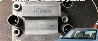
| 3 | Explanation of the ignition coil designation (Catalogue number) - 2111-3705010; |
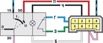
| 4 | Electrical diagram of the ignition coil VAZ 2114 injector 8 valves; |
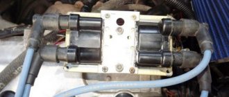
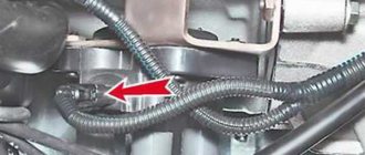
| 5 | Where is the ignition coil of VAZ 2114 8 valves, VAZ 2113, VAZ 2115; |
| 6 | Analogues of the ignition coil VAZ 2114 injector 8 valves, VAZ 2113, VAZ 2115 type 2111-3705010-02; |
| 7 | Pinout of the ignition coil for VAZ 2114 model 2111-3705010-02 (54.37005); |
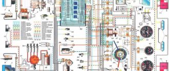
| 8 | Schematic diagram of engine control with an ignition coil VAZ 2114 injector 8 valves; |
| 9 | Electrical circuit diagram for controlling the propulsion system of model 11183 (l,6i).with ignition coil of brand 2111-3705010-02 (54.37005): |
| 10 | Signs of a malfunctioning ignition coil VAZ 2114 8 valves, 2113, 2115; |
| 11 | Checking the ignition reel of a VAZ 2114 injector 8 valves; |
| 12 | Replacing the ignition coil on VAZ 2114, 2113, 2115 cars; |
| 13 | Literature on passenger cars VAZ 2114, 2113, 2115 models and their modifications. |
Description and purpose
Ignition coil VAZ 2114 8 valves, VAZ 2113, VAZ 2115 are two two-output ignition reels mounted in a single casing. It is designed to convert low on-board voltage (12 volts) into high sparking voltage. Sparking occurs in two pots at once (1-4 and 2-3). The ignition solenoid is connected to the spark plugs by high-voltage wires with permanent tips.
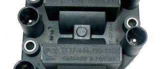
Below, in the figure, the design of the ignition coil of the VAZ 2114 8 valves is presented
Which is better?
SOATE devices manufactured in Stary Oskol have proven themselves to be the most reliable ignition modules.
Module structure
The module consists of two ignition coils and two high-voltage switch switches.
The coil generates a high voltage pulse, and it is a simple transformer with two windings, primary (induction voltage about 500 V) and secondary (induction voltage at least 20 kV). All this is assembled in a single housing, on which there is a connector for signal wires (from the engine control unit) and four terminals for high-voltage wires.
The module operates on the principle of an idle spark - it distributes sparks in pairs to cylinders 1-4 and 2-3 according to impulses transmitted from the ECU.
The principle of operation of the ignition coil VAZ 2114 8 valves, model 2111-3705010-02
The current in the primary windings of the ignition coils is controlled by a controller that uses information about the engine operating mode received from the engine control system sensors. To switch the primary windings of the ignition coils, the controller uses two powerful transistor valves.
From the ignition coil of the VAZ 2114 8 valves, a high voltage pulse is supplied to two cylinders at once: 1 - 4, 2 - 3. In one cylinder the compression stroke ends (working spark), and in the second the exhaust stroke (idle spark) occurs.
Due to the constant direction of current in the primary and secondary windings, the sparking current of one spark plug always flows from the central electrode to the side electrode, and the second - from the side to the central one.
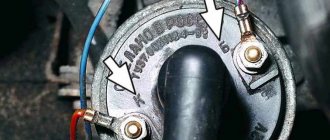
The ignition coil of the VAZ 2114 injector 8 valves works according to the following principle. The vehicle's electrical system voltage is supplied from the ignition switch to contact “15” of the ignition coil. Next, the controller switches the pulse to terminal “1b”, the circuit of the primary winding of the ignition coil, as a result of which the secondary winding outputs high voltage to the spark plugs of cylinders 1 and 4. And the controller switches the pulse to terminal “1a”, the circuit of the primary winding of the ignition coil, as a result which causes the secondary winding to output high voltage to the spark plugs of cylinders 2 and 3.
Share your story
The tightness of the carbolite lid in the casing is ensured by a gasket. As a result, high voltage is formed in the secondary, which goes through high-voltage wires to the spark plug. According to the design of the magnetic circuit, ignition coils are divided into two types: - With an open magnetic circuit. Types of high-voltage elements Above is a description of a simple design of a voltage-increasing transformer that provides discharges to all engine cylinders.
When the engine crankshaft rotates, the sensor rotor rotates.
Replacing the ignition coil on a VAZ is quite simple.
Capacitors C1 and C2 and the inductor reduce voltage ripple in the switch's power circuit, and the VD6 diode KDB protects against reverse polarity. The dual system is used for cylinders that operate in the same phase. Direct current flows through the primary coil.
TB above emitter potential. When connecting the coil to the car’s ignition system, in principle, you should not have any difficulties if, during preliminary dismantling, you marked or remembered which wires are connected where. Ignition system contact and without 1 part
Explanation of the ignition coil designation (Catalogue number) - 2111-3705010;
The designation of a part or assembly is a unique number in a single form. Assigned to only one part. The numbering of designations for assembly units and parts is carried out according to a unified seven-digit system. Designation - 2111-3705010-02 is deciphered as follows. The first four digits before the dash indicate the model of the base car or engine, chassis, body. In our case: 2111 is the engine model. The first two digits after the dash indicate the group number, in this case 37 - electrical equipment. The next two digits are the subgroup number. In our case, 05 is the ignition coil. The last three digits of the seven-digit number indicate the serial number of the part. The last two digits after the second dash indicate the interchangeability of the part. ХХХХ-ХХХХХХ-00 (to-09) - interchangeable. ХХХХ-ХХХХХХХ-10 (up to 19) are interchangeable with each other but not interchangeable with ХХХХ-ХХХХХХХ-00 (up to-09) and so on.
Pinout, connection diagram and check of the VAZ ignition coil
Today we will look at the design and diagrams of ignition systems for VAZ cars of all major models. Since carburetor versions of VAZ are practically history, we will dwell in detail on the ignition systems of injection cars. Their ignition system is based on an electronic ignition module. We also recommend that you carefully consider the choice of spark plugs and the quality of high-voltage wires, because the quality of the spark and, accordingly, the operation of the ignition system as a whole will depend on them. The information is intended as a reference guide for self-repairing a car.
Errors
A module malfunction can also be determined using an error scanner. Error codes associated with the module are:
- R-3000, R-3001, R-3002, R-3003 and R-3004 - gaps in sparking, the module itself, spark plugs, high-voltage wires or the ECU may be to blame;
- R-0351 - the coil of cylinders 1-4 does not work;
- R-0352 - the coil of 2-3 cylinders does not work.
The scanner readings do not yet indicate problems with the module itself.
It is possible that the spark plugs are not working or the high-voltage wires are broken, but if we initially diagnosed them, then the fault lies entirely with the ignition module. In this case, we can repair it ourselves, or buy a new one, which is faster, easier and guarantees uninterrupted operation of the ignition system. Good luck to everyone, strong spark and good roads!
Pinout and diagram of the VAZ ignition coil
Pinout of ignition coil modules for various car models of the VAZ family:
Ignition VAZ 2101
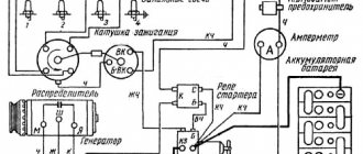
1 – generator; 2 – ignition switch; 3 – ignition distributor; 4 – breaker cam; 5 – spark plugs; 6 – ignition coil; 7 – battery.
Ignition VAZ 2106
1 – ignition switch; 2 – fuse and relay block; 3 – EPHH control unit; 4 – generator; 5 – solenoid valve; 6 – microswitch; 7 – spark plugs; 8 – ignition distributor; 9 – ignition coil; 10 – battery.
Ignition VAZ 2108, 2109
Ignition VAZ 2110
Ignition VAZ 2111
Ignition VAZ 2112
Ignition VAZ 2114
Diagram of a non-contact ignition system: 1 – non-contact sensor; 2 – ignition distributor sensor; 3 – spark plugs; 4 – switch; 5 – ignition coil; 6 – mounting block; 7 – ignition relay; 8 – ignition switch.
Diagnostic procedure
The diagnostic procedure can be as follows:
- Disconnect the connector with signal wires from the module.
- Turn on the ignition and check the voltage at terminal 15 (central) of the control wire block. The rated voltage is 12 V. A drop or absence of voltage when the battery is charged indicates that the engine control unit does not supply power to the module. This means the reason lies in the ECU.
- We check the resistance of the primary windings of the coils - put the multimeter in resistance measurement mode and take readings from the rightmost and central terminals, then from the leftmost and central terminals. The nominal resistance of the primary windings is approximately 0.5 Ohm.
We measure the resistance of the secondary windings between terminals 1-4 and 2-3 high-voltage wires. Nominal value: 5.4 kOhm. If the readings do not correspond to the nominal value, the coil is not working correctly.
Check the module for a short circuit. To do this, install one tester probe on the central pin 15, the second on the metal body. The device should show the absence of a short circuit (one or infinity). Otherwise, one of the coils has shorted to the housing.
How to check the ignition coil of a VAZ
If the ignition coil is faulty, the engine will not start. A characteristic sign of a faulty coil is its increased temperature when the ignition is turned off. This is easy to determine by touch.
Signs of a faulty ignition module may include the following:
- hesitant engine starting or failure to start;
- failures during sudden changes in speed;
- high fuel consumption;
- two cylinders do not work, the engine is feverish;
- lack of dynamics;
- a sharp drop in power;
- drop in power and thrust after warming up.
These symptoms may not only be caused by the ignition module. To determine the malfunction, it is enough to spend a few minutes diagnosing spark plugs, high-voltage wires and caps. This will eliminate the remaining elements of the ignition system and make sure that it is the ignition module that is faulty.
Checking the ignition coil is performed in one of 2 ways. The simplest one is to remove the central wire from the breaker-distributor, bring it to the motor housing and turn it with the starter, and a running spark should appear. After this, we check the energy supply to a separate spark plug, for which we unscrew the working spark plug, bring its contact to ground and attempt to start the engine. In this case, the spark should come from the wire to ground. If it is absent, the reason will be a malfunction of a system element such as the ignition coil.
To check the module in the second way, we only need a multimeter, then follow the step-by-step instructions:
- We check the power supply and the presence of pulses supplied from the ECU. We check the power between the central terminal (15) of the wire block connected to the module and the engine ground. When the ignition is on, the voltage should not be less than 12 V. Otherwise, either the battery is dead or the ECU does not work.
- We check the pulses from the ECU on the wiring block. We install one tester probe on connector 15, the second on the far right, then on the far left. The assistant cranks the engine with the starter, and at this time we record short-term voltage surges with a tester. If there are no impulses from the ECU, it is he who is to blame.
- We check the resistance on the secondary windings of the coils. We put the tester in resistance measurement mode and measure it at the high-voltage terminals of the module cover. Between pins 1 and 4 and pins 2-3, the resistance should be 5.4 kOhm. Otherwise, the module must be replaced.
- We check the resistance of the primary windings between contacts 15 and the rightmost, then the leftmost terminals. Nominal - 0.5 Ohm. Deviation is not allowed.
- Check the module for a short circuit. In ohmmeter mode, install one multimeter probe on the central terminal, the second on the metal body. There shouldn't be any resistance. If the device detects at least some resistance (other than unity or infinity), the module must be replaced.
Main signs of failure
Drivers need to take into account during operation that breakdowns can occur both due to failure of the mechanical part and due to problems with the electrical system. Popular mechanical problems manifest themselves in the following factors:
- the lock is stuck in one position and there is no way to unlock it without using significant effort;
- the steering column is jammed;
- an attempt was made to gain unauthorized access to the lock using a master key or other object unsuitable for this purpose.
The electrical part may also fail. This can be determined by the following factors:
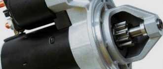
- the starter does not rotate after turning the key to the desired position;
- The dashboard indicator lights do not light up or go out after a short time;
- the operation of devices activated through the lock positions is unstable or absent.
Other factors that are less common among motorists may also occur. They are resolved according to the identified breakdowns.
You should not delay solving the problem that has arisen, as this can provoke unpredictable negative consequences.
Connecting and replacing VAZ short circuit
The procedure for removing and installing the ignition coil on old VAZ models:
- First, disconnect the central high-voltage wire leading to the distributor (ignition distributor).
- Disconnect all power wires from the coil contacts. Since they are fastened with nuts, you will need an 8 wrench for this.
- If you don’t know which wires to connect to which connector later, it’s better to immediately remember or mark them somehow, so that later during installation you can connect them correctly.
- Unscrew the coil housing. It is attached to a clamp (clamp), which is pressed to the car body with two nuts.
- After the work has been done, you can remove the ignition coil and replace it if necessary.
For new type VAZ cars:
- We remove the “minus terminal” from the battery.
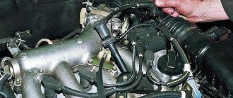
- Remove the top protective cover of the engine. If the engine volume is 1.5 liters, then this part is missing and this step is skipped.
- We remove the high-voltage wires from the coil.
- Now, using a 13mm wrench, unscrew the two fasteners.
- Using a 17mm wrench, loosen one bolt securing the coil.
- We take out the module.
- Use a hexagon to unscrew the coil from the holder.
- Assembly is carried out in reverse order.
Particular attention should be paid to the connection, since high-voltage wires must be located in the strict order provided for by the design. If this is not done, the car will stall or the engine may not start at all.
Replacing the ignition coil on a VAZ is quite simple. Even a novice motorist can do this in his garage, and if everything seems too complicated, contact a car service center. Particular attention should be paid to the choice of product, since this will determine how well the engine and ignition system will work.
see also
Comments 20
Thanks everyone for the advice! I installed the VAZ coil, connected the wires, and started the car!
There is no spark not with this not with the VAZ coil :(
Green, light green, yellow, brown + from distributor
The coil needs another one with two contacts B-battery K-cams, tachometer
Is the wire from the distributor also on “K”?
Yes, in the place with the tachometer, I have a green wire, and a yellow one is plus
The entire bunch is connected to terminal K green. and brown?
the coil is from Ufa, on the VAZ there is nowhere to connect the third terminal - there is no terminal for it on the starter... I would change the coil to the VAZ one... if you connect this one, you find the wire on which + appears when you turn on the ignition and hang it on B, you hang the rest if you look in the photo, then to the lower contact, these are wires from the distributor and from the tachometer...
I connected everything like this, but there is no spark! Even when you turn on the low beam, the side lights go out, and the turn signals on the rear headlights come on and the low beam doesn’t light up, the rear right side light doesn’t light up yet
Is the coil definitely alive? try to directly close the variator, they sometimes burn out, you can’t drive with it closed, the coil will burn out, but you can’t close it for long to check... well, and again check the contacts in the distributor, the capacitor... as for the light and music - look for where the ground on the headlights is lost...
The distributor is new! I plugged a light bulb into the high-voltage wire from the coil to the distributor, placing it on - (radiator) did not light up when starting the starter
Is the coil definitely alive? try to directly close the variator, they sometimes burn out, you can’t drive with it closed, the coil will burn out, but you can’t close it for long to check... well, and again check the contacts in the distributor, the capacitor... as for the light and music - look for where the ground on the headlights is lost...
I also accidentally connected the wire from the distributor to the terminal of the coil with the + terminal from the ignition; the distributor was short-circuited; the contacts in the distributor and the ends of the wires of the distributor and + from the ignition melted. Could this cause the coil to burn out?
Russian spare parts are so Russian that new does not mean working, everything needs to be checked. I don’t understand, why is there a light bulb there? you hold the high voltage wire with a gap from any ground and turn the starter, see if there is a spark... if the contacts in the distributor are already burnt, all the more you need to get into it, clean the contacts, set the gap... but I would still change the coil to a VAZ B117...
I replaced the shorted distributor with a new one, and I will change the coil tomorrow with the high-voltage wires! Does the coil take minus from the body?
the plus goes to the coil from the lock, and the minus comes from the distributor, the contact group is at ground...
B - 'battery' - the wire on which 12V appears when the ignition is turned on. 'Unnamed' - to the distributor, there is also a wire from the tachometer. On 'Vk' there is a wire from the starter, to enhance the spark at the moment of starting
The colors of the wires do not match and in the diagram with the VAZ internal combustion engine there is a coil with 2 terminals
Source: www.drive2.ru
VAZ models 8 and 16 valves
Despite the similarity in engine design, the ignition system of the 1.5-liter injection 16-valve engine differs from the 1.6 16-valve engine. The 1.6 liter engine uses an electronic contactless ignition system with individual coils on each spark plug. Therefore, there was no need for an ignition module. Such a system is more reliable and cheaper to operate, since if one coil fails, there is no need to replace the entire module.
The 16-valve 1.5-liter VAZ 2112 injection engine used the same non-contact ignition system as the 8-valve engine, but a different ignition module was installed. Its catalog number is 2112-3705010. The design of the module remains the same - two ignition coils (for cylinders 1-4 and 2-3) plus switch keys in a single block. The spark is supplied to the cylinders in pairs using the idle spark method. This means that sparking occurs in two cylinders simultaneously - in one on the compression stroke (working spark), in the second on the exhaust stroke (idle spark).
Module design
Before you begin repairing the ignition module, it is worth understanding what it consists of. So, let's look at the design of this element:
- Two ignition coils that generate a high-voltage pulse.
- Dual channel switch.
If there are problems with the operation of the ignition module, there are reasons for this. It is worth warning that in the event of a malfunction, the “Check Engine” warning light will not light up: engine stops, loss of spark, interruptions in the operation of the power unit, etc.
For diagnostics and repairs, basic knowledge is required not only in conventional electrics, but also in the principles of auto electrics. Also, for a successful process you will need skills in working with a digital multimeter.
Repair process
Often, the high-voltage pulse disappears in cylinders 2 and 3 . So, to begin repairing the ignition module, of course, you will need to dismantle it. To do this, disconnect the high-voltage wires and unscrew the assembly itself from the fastenings. When the preparatory operations are completed, you can proceed directly to the repair process:
- We tear off the aluminum plate.
Use a screwdriver to open the aluminum plate
Scheme of soldering wires and arrangement of elements on the boards
Diagram of the assembled ignition module
Completely assembled ignition module
Video about repairing the ignition module on a VAZ-2112
The video material will tell you about repairing the ignition module, as well as how to remove it from the car.
Video on repairing KZ VAZ
Source
| 1 | accumulator battery; |
| 2 | main relay; |
| 3 | ignition switch; |
| 4 | spark plug; |
| 5 | ignition coil VAZ 2114 8 valves model 54.37005; |
| 6 | controller; |
| 7 | crankshaft position sensor; |
| 8 | master disk. |
| 1 | ignition switch; |
| 2 | main relay; |
| 3 | battery; |
| 4 | atmospheric filter; |
| 5 | diagnostic connector; |
| 6 | dashboard; |
| 7 | tachometer; |
| 8 | check lamp; |
| 9 | speedometer; |
| 10 | immobilizer sensor with indicator; |
| 11 | immobilizer manual device; |
| 12 | electric fan of the engine cooling structure; |
| 13 | electric fan relay; |
| 14 | controller; |
| 15 | DTOZH; |
| 16 | ignition coil VAZ 2114 8 valves, VAZ 2113, VAZ 2115; |
| 17 | spark plug; |
| 18 | DPRV; |
| 19 | sprayers; |
| 20 | throttle assembly; |
| 21 | TPDZ; |
| 22 | DMRV; |
| 23 | empty control; |
| 24 | Lambda probe; |
| 25 | car speed sensor; |
| 26 | DPKV; |
| 27 | DD; |
| 28 | crankshaft pulley; |
| 29 | gasoline filter; |
| 30 | petrol pump relay; |
| 31 | gasoline tank; |
| 31 | gasoline unit; |
| 32 | two-way valve; |
| 33 | gravity throttle; |
| 34 | reverse breather; |
| 35 | check valve; |
| 36 | adsorber purge throttle; |
| 37 | adsorber; |
| 38 | separator. |
| 1 | spark plug 4 pots; |
| 2 | spark plug 3 cylinders; |
| 3 | spark plug 2 pots; |
| 4 | spark plug cylinder 1; |
| 5 | ignition coil VAZ 2114 8 valves; |
| 6 | diagnostic connector; |
| 7 | 1 pot sprayer; |
| 8 | injector 2 cylinders; |
| 9 | 3 pot sprinkler; |
| 10 | 4 cylinder injector; |
| 11 | ECU; |
| 12 | fuel pump switch; |
| 13 | to the electric cooling radiator fan; |
| 14 | connector for connecting the engine radiator electric fan; |
| 15 | main relay for engine control mode; |
| 16 | DMRV; |
| 17 | remote sensing; |
| 18 | DTOZH; |
| 19 | empty traffic controller; |
| 20 | adsorber purge throttle; |
| 21 | DPKV; |
| 22 | DD; |
| 23 | oxygen concentration sensor; |
| 24 | to the ignition switch; |
| 25 | Immobilizer ECU; |
| 26 | immobilizer sensor with signaling device; |
| 27 | car speed sensor; |
| 28 | spare pad; |
| 29 | to the battery positive; |
| 30 | DPRV; |
| 31 | block for connecting to the car's electrical network; |
| 32 | fuel unit; |
| F1 | fuse for the ECU and engine control structure circuits; |
| F2 | ECU fuse; |
| F3 | fuel pump line fuse |