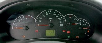
Here I am figuring out how to connect the device from a VAZ2110! First, I scoured the Internet and found the pinout of VDO devices!
1 Brake fluid level lamp. 2 Emergency lamp. 3 High beam lamp. 4 Fuel level indicator. 5 To speed sensor. 6 Check. 7 Brake fluid level lamp. 8 Left turn lamp. 9 Right turn lamp. 10 Instrument lighting. 11 Minus 12 power supply instruments 13 Fuel lamp 14 Minus 15 Low -voltage input of the tachometer we connect to the injector 16 high -voltage input of the tachometer we connect to the coil 17 PLUS PLUS COLLECTION FRIENT 19 LAMP LAMP LAMI LAMP 22 22 go to the brain if the carburetor does not connect 23 instrument power plus 24 Handbrake lamp 25 Battery charge lamp 26 Oil pressure lamp
Now the pinout of Tavria devices
1 Weight minus 2 Gasoline 3 Power plus 4 Long range 5 Brakes 6 Turns 7 Choke 8 Temperature 9 Dimensions 10 Oil 11 Battery 12 Gasoline Then we reconnect everything and everything works smoothly!
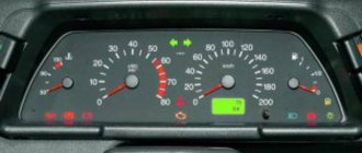
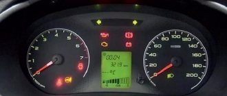
Let's be honest - the VAZ 2110 does not have the most beautiful “native” instrument panel, either on the first cars or on the “improved” ones. Therefore, many owners of this model are trying to make it more modern and somehow decorate it (with LEDs, beautiful lights, etc.).
But, before you decide on some kind of upgrade, it is necessary that you have before your eyes the pinout of the instrument panel for the VAZ 2110, otherwise you can simply get lost in a heap of wires, sensors and buttons. Moreover, it will be useful regardless of whether you completely change the panel, or simply make some additions to the dashboard of your VAZ 2110.
Instrument panel VAZ 2110
Connection knowledge
Before starting dismantling work, you need at least a conventional pinout on paper, otherwise it will be very difficult: you will need to “trace” every wire and every connection that is on the “path” from the devices to the power button.
In fact, the pinout of the VAZ 2110 dashboard is not so difficult to understand, but there are differences between cars produced in different years and at different factories. There is an old model, there is one with a mechanical odometer, and a new (Euro) model, so there are differences in the pinout of the instrument panel, depending on the type to which it belongs.
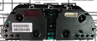
General diagram of devices
If you look from the back of the instrument panel, here it is in sequence - from top to left to right:
- Fuel level indicator;
- Combination of instrument lighting lamps;
- Right turn control;
- Left turn control;
- Tachometer;
- Next is the block, there are a lot of plugs in it;
- And the top part of the dashboard is completed by an antifreeze temperature indicator.
VAZ 2110 dashboard connection diagram
The lower part of the dashboard (also from left to right and from the back of the dashboard). The following part of the instruments is located here:
- high beam controller (bulb);
- alarm controller;
- brake fluid level control lamp;
- speedometer;
- CHECK ENGINE controller;
- battery charge control;
- parking brake controller;
- oil pressure controller;
- air damper controller in the carburetor;
- outdoor lighting controller.
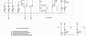
White block
The connector number, wire color and the unit (assembly) to which it goes are located in the white block as follows:
- The first connector has a black wire. Its purpose is the body (mass);
- In the second - red-brown - this is a low-voltage supply from the electronic control unit - tachometer;
- The third, yellow one is also a tachometer, but this is a high-voltage supply from a coil;
- The fourth, red-blue is Const from the battery + 12V, going through the sixth fuse;
- The fifth, green-white - it is intended to indicate the coolant temperature;
- Sixth, green-yellow – for size fuse F1;
- The seventh connector does not have its own color and goes to the “choke”, the throttle valve;
- Eighth, red and white - CHECK ENGINE light;
- In the ninth and tenth there are 2 orange wires each, leading to 2 power fuses F19+12V;
- In the eleventh there are 2 blue-brown wires leading to the “BK” terminal of the parking brake;
- The twelfth, brown-white is the output “D” of the generator;
- Thirteenth, gray and blue – for the oil pressure sensor.
Coolant temperature indicator
The device operates in combination with a coolant temperature sensor, which is installed in the cylindrical heads. When the temperature indicator shows a resistance of approximately 650-1340 ohms on the board, the arrow should be located at the initial marks of the scale.
If the resistance results on the dashboard have reached 76-88 OM, then the arrow should reach the section of the scale marked in red. The arrow reaches the end of the red scale when the sensor resistance is 41-51 ohms.
If the resistance data and the arrow level do not match, then the machine requires repair or replacement of parts.
Nuances of work
However, these pinout diagrams for the VAZ 2110 are, so to speak, basic, mostly the same, but there are also differences in color markings (especially by manufacturer). Therefore, you need to either use the instruction manual that came specifically with your car, or, armed with a marker and self-adhesive labels, “write everything out” in detail and not get confused when installing a new instrument panel.
Connecting wires to the VDO panel on a VAZ 2110
Connecting wires to the “Schetmash” panel in Kursk on a VAZ 2110
Connecting wires to the “AP” panel in Vladimir on a VAZ 2110
Connecting wires to the panel from the Kalina car to the VAZ 2110
During subsequent assembly, there will probably be a lot of devices that are not taken into account here, and, taking into account modern realities, many car owners plan to install them on the updated dashboard.
What problems can arise with the instrument panel on the VAZ 2110?
The reasons why the instrument cluster stopped working are divided into two types:
- incorrect operation of the backlight or part of the indicators;
- complete shutdown of the panel.
Instrument panel backlight does not light up
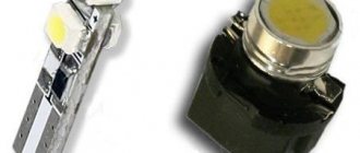
Several light bulbs are used to illuminate the combination. A darkened section indicates one or two burnt out bulbs. If the backlight fails completely, you should check the fuse responsible for the power circuit. It is located in the cabin block in the first place on the left in the top row, and has a nominal value of 5A.
The cause of the indicators not working may be problems in the electronics. So, a malfunction in the engine controller is a possible reason for the failure of the Check Engine lamp.
If, in the event of a complete failure of the instrument lighting on a VAZ 2110, the rear license plate lighting lamps and the left side side lights stop working, all these symptoms indicate a failure of the fuse link.
Complete node failure
Complete failure of the instrument cluster means turning off the dial indicators, warning lamps, and display. The main cause of the malfunction is the blown fuse located in the cabin unit. The 10 A insert is installed second from the right in the bottom row.
You can verify that the fuse has failed by looking at the direction indicators not working. If the new insert burns out, you should look for the problem in a short circuit in the wiring. It is forbidden to try to solve the problem by installing fuses of increased ratings or “bugs”, as this may cause a fire.
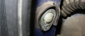
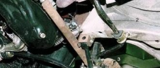
Arrows jump up and down
The reason for the chaotic movement of the arrows is a poor mass signal due to rotting or loosening of the wire fastening. According to the factory wiring diagram, ground comes from a wire attached to the engine panel. The bolt attachment point is located behind the audio system installation location. There may be other points for conducting the mass wire, obtained as a result of repairs performed by the previous owners of the car. After locating the contact point, you need to securely crimp the fastener and check the integrity of the conductor with a tester.
Instrument panel problem
On many used cars, instrument failures are often encountered due to the destruction of printed circuit board elements. To check, you need to pull the combination out of the panel without disconnecting the power supplies.
Cigarette lighter problem
A common cause of incorrect operation of the instrument panel on the VAZ 2110 is the cigarette lighter. When high-power consumers are connected, the fuse and the power supply to the instrument cluster located next to it burn out. The 25 A cigarette lighter insert is located to the left of the indicator panel (discussed in the complete unit failure section).
Connecting the trip computer
The mentioned diagram took into account only one, brown wire leading from the red block to the trip computer, but this is clearly not enough. Therefore, let's see how the pinout occurs here.
- The fuel consumption signal from the electronic control unit is indicated by a green wire;
- Orange leads to terminal “15” in the ignition switch;
- Red and white - to terminal “30” in the ignition switch;
- Black, which is common, goes to ground;
- The speed indicator corresponds to brown;
- The positive terminal of the fuel sensor is green and red;
- Responsible for lighting the dashboard white, it leads to the light control.
Make sure that the board is not damaged, on which, in fact, uninterrupted reading of information from your VAZ 2110 depends, and providing it to you through all those sensors and devices that you always see in front of you.
Probably, hardly anyone will argue with the fact that the VAZ “ten” is not the pinnacle of design thought. However, there is nothing surprising here, because this car was designed back in the last century. At the same time, the compensator, and quite a serious one, in this case is the price. In other words, a certain compromise is proposed - the imperfection of the car in exchange for an acceptable cost. Well, the choice is ultimately made by the car owner himself, deciding whether this option is suitable for him.
Why you should know the pinout
But before you start this kind of upgrade, you need to understand which wire leads where. The pinout of the instrument panel of a VAZ-2110 car is a very important point when “tuning”. Without this, you risk simply getting confused in a fairly large number of wires, buttons and various sensors. The pinout will be useful in any case - both when making minor improvements and when completely replacing the instrument panel.
The process of installation and dismantling itself is quite labor-intensive, but if you know the correct sequence of actions, then there is nothing particularly difficult about it.
For these works you will need a minimum set of tools - a screwdriver and pliers.
For those who are doing this for the first time, it is best to stock up on self-adhesive pieces of paper, like those on which prices are written in stores, and a pen. With their help, at the time of disassembly, you will indicate, firstly, the sequence of dismantling the parts, and secondly, which wire is connected where. At first glance, this may seem time-consuming, but in fact, for beginners, such markings will help them put the panel back together faster.
At the same time, before starting work, it is best to stock up on a pinout diagram - at least conditional. After all, during the work process you need not to confuse anything and correctly understand each wire and connection during the reassembly process. It is worth noting one very important point. By and large, understanding the pinout of the panel of the “tenth” family will not be difficult even for a beginner.
But you need to remember that there are certain differences here, depending on the plant where the car was manufactured and the year of its manufacture. For example, the instrument panel may be an old model, with a mechanical odometer. If the odometer is electronic, then this is a newer version. Accordingly, there are certain differences in pinout between these panels.
What does the dashboard consist of?
The Priora instrument panel contains all the necessary parts that no modern car can do without:
- regulator of external lighting and internal panel lighting;
- switch for turning, side and headlights;
- signal regulator;
- car instrument cluster;
- windshield wiper and washer regulator.
This is how the dashboard works
In addition, the panel contains an ignition switch connected to the anti-theft system. It contains 3 positions. Among the secondary mechanisms, we can note the presence of regulators for the rear window heating system, alarm and interior cooling. It is also worth mentioning the glove compartment, built-in clock and radio input jack.
Sometimes a certain panel element becomes unusable and you have to look for ways to replace it. In this case, you will need to disassemble the interior. Below is how to disassemble the instrument panel.
Which wire goes where?
First, let's look at the back of the instrument panel. At the top there are:
- fuel level indicator;
- dashboard lighting lamps;
- control of right and left turns (separately);
- tachometer;
- block with many plugs;
- coolant temperature gauge.
As you can see, there is really nothing particularly complicated here. At the bottom of the instrument panel on the back side there are controllers:
- high beam;
- "emergency lights";
- CHECK ENGINE;
- battery charge;
- parking brake;
- oil pressure;
- air damper (for models with a carburetor);
- outdoor lighting work.
Features of connecting BC
In conclusion, I would like to dwell in more detail on such a point as installing an on-board computer. In the typical pinout diagram shown just above, there is only one wire leading to it - brown. But for the correct operation of this device, this alone will not be enough. Therefore, here is a complete pinout diagram for connecting the on-board computer:
- Green wire – comes from the electronic control unit, needed to obtain information about fuel consumption.
- Orange – goes to the ignition switch, to terminal 15.
- White-red - in the same place, only to terminal 30.
- The common ground wire is black.
- Brown – needed to take speed data.
- Red-green - to the positive circuit of the fuel level sensor.
- White - leads to the light control, which is responsible for the lamps that illuminate the instrument panel.
Removal and modification guide
If indicators appear while driving, this does not always indicate a malfunction of the components. Perhaps the problem is simply a malfunction of the sensor responsible for the operation of the unit. Or the problem may be a broken wiring or bad connector contacts. Therefore, there is no need to panic right away. The video below shows the result of tuning the “tens” control panel. The author of the video, proVAZ-2110, planned to make the tuning in such a way that the color of the speedometer and other sensors would be white, but he did not take into account that the plastic on the dashboard was originally yellow. Accordingly, the author of the video was not pleased with the end result.
Often, car enthusiasts decide to tune their dashboard to improve the appearance of the car's interior. To do this, you can simply remove the panel trim and simply remove the regular bulbs. By installing LEDs instead. Such a control panel will enhance the brightness of the indicators. If necessary, you can install a more modern europanel, which will transform the interior of the “tens”. If you just want to tune the control panel, you can install a new trim on it.
To do this you will need:
- First, turn off the power to the vehicle's on-board network. To do this, disconnect the negative cable from the battery.
- Next, the instrument panel is dismantled; for this, all the necessary bolts are unscrewed.
- The next step is to remove the control panel fastenings to the trim. Having done this, you can remove the control panel itself from the socket. After these steps, you can dismantle the glass mask.
- Then all the pads that lead to the panel are turned off.
- Now a new overlay is being installed on the instrument panel of the VAZ 2110. If necessary, install LEDs instead of conventional light bulbs. Further assembly is carried out in reverse order.
You should always be careful when working with electricity. If you damage even one wire when removing or installing the dashboard, this can lead to dire consequences, including non-functioning devices on the dashboard. For example, owners of “ten” cars are often faced with the problem of the speedometer not working, which is usually associated with the wiring. Therefore, always be careful when working with the dashboard. In addition, after disassembling the instrument panel, or rather removing the arrows, there is a possibility of displaying distorted readings.
Loading …