The ignition system of any modern car consists of many different components designed to ensure normal starting of the internal combustion engine. One of such devices is the ignition coil of the VAZ 2109. You can learn more about the features of this device on the “nines”, as well as its malfunctions and diagnostics from this material.
Features of the ignition coil device
Regardless of which engine your VAZ 21099 is equipped with - an injector with nozzles or a carburetor - the purpose of the short circuit is the same. The VAZ 2109 ignition coil is designed to produce a good spark at the electrodes of the spark plugs, which is necessary to ignite the combustible mixture. A short circuit on an injector or carburetor allows you to generate high-voltage pulses that provide a high-quality discharge between the electrodes. In simple terms, a VAZ ignition coil is a transformer that operates in a pulse mode and allows you to convert a 12-volt voltage into 20-30 thousand volts.
Removing the short circuit from the seat
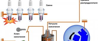
To ensure the ignition of the flammable mixture, high-voltage circuits (wires) are used to transmit the impulse. The operating principle of the system as a whole is quite simple - after turning the key in the ignition switch, the distributor receives an impulse and transmits it to the short circuit, where it is converted. After this, the breaker distributes the spark in accordance with technical regulations - to certain cylinders. As for the design of the short circuit, on a VAZ 2109 carburetor or injector, its circuit is quite simple - it consists of primary and secondary windings, which are wound on a magnetic circuit.
The primary winding is wound with thicker wire with fewer turns, and the secondary winding has more turns but less thick wire. The high-voltage pulse appears as a result of electromagnetic induction and charge accumulation, and it is transmitted during the shutdown of the primary. After its transmission, the air-fuel mixture ignites, which helps start the engine (the author of the video is the Avtoelektika HF channel).
Installation Guide
How to install BSZ with your own hands on the “seven”? How to properly set and adjust the device? First you need to prepare everything you might need.
Tools and materials
To complete this task you will need:
- a set of keys;
- self-tapping screws;
- screwdriver set;
- construction drill.
Stages
Installation of electronic ignition must be carried out on a de-energized on-board network, otherwise a short circuit may occur in the system.
So disconnect the battery and then follow these steps:
- Disconnect all high-voltage wires from the spark plugs.
- Dismantle the distributor cover.
- After this, by rotating the crankshaft, it is necessary to set the slider to a position perpendicular to the axis of the power unit. Also mark the location on the middle mark of the distribution element scale, this will allow you to make adjustments without any problems in the future.
- The distributor fixing nut must be unscrewed, after which the device is dismantled.
- A non-contact regulator is installed instead of the dismantled distributor, while the slider and housing must be placed in the desired position in accordance with the previously established marks.
- The device cover is installed.
- Then you need to connect the high-voltage cables with the spark plugs.
- After completing these steps, you can replace the coil. In general, this task is quite simple, but when performing it, you should take into account the position of contacts B and K. If they are different on the new short circuit, then the element should be rotated relative to the fastener so that the contacts are located similar to the one that was installed previously.
- At the final stage of installation, the switch is installed; the best option would be to place it between the washer expansion tank and the headlight. The mechanism is fixed using self-tapping screws, and the so-called zero wiring should be brought out under one of them. As for the radiator, it should be leaned against the body.
How to check the ignition coil?
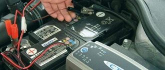
Before checking the ignition coil in a VAZ 21099 injector or carburetor, you need to prepare a tester (multimeter) and disconnect the battery from the power supply. Checking the switching on of the device, its connection and connection can be carried out without dismantling the short circuit.
Diagnostics of the performance of a short circuit on the 21099 injector includes the following steps:
- First you need to disconnect the high-voltage wires that go to the short circuit terminals. To do this, use a size 8 wrench and unscrew the nuts securing the cables to terminals K and B. Before disconnecting the wires, you must remember their position; under no circumstances should they be mixed up during further installation!
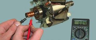
- Next, the ignition coil is directly checked, in particular the primary winding. To do this, connect one multimeter probe to terminal B and the other to terminal K on the primary. Having done this, you can activate the multimeter in ohmmeter mode. If the primary is serviceable, then the resistance level as a result of diagnostics should be about 0.4-0.5 Ohm.
- The next step will be to diagnose the secondary structural element; this will also require a multimeter. To check the serviceability of this component, you need to connect one lead of the multimeter to pin B of the short circuit, and the second to the connector for the high-voltage cable. At this stage it is also necessary to check the resistance. If the secondary is serviceable, then the resistance parameter as a result of diagnostics should be 4.5-5.5 kOhm.
- The final step in the test will be to diagnose the health of the insulation, that is, you will look for a possible short circuit that could occur in the system. To check for a short circuit, one lead of the multimeter should be connected to connector B of the device, and the second to ground. Alternatively, you can use a short circuit housing. If everything works correctly, then the resistance parameter should be quite high - within 50 mOhm. If this value is very different, then there is still a short circuit. Please note that if at least one of the stages shows a breakdown in the operation of the device, then it must either be repaired or replaced. If the tested unit is working normally, but there are still problems with the ignition system, then it is necessary to check the high-voltage wires, spark plugs, and distributor.
Typical unit malfunctions and ways to eliminate them
In what cases may it be necessary to replace the mechanism:
- If there is a short circuit in its operation. In particular, we are talking about a short circuit between the turns of one of the windings.
- If there is a break in the electrical circuit of the secondary and primary. Finding it can be problematic; usually, with such a problem, experts recommend completely changing the short circuit.
- Also, one of the characteristic faults for domestic “nines” is an insulating breakdown of the secondary to ground, that is, the short-circuit housing.
- The presence of defects in the body and cover of the device. If the short circuit can still work with damage to the body, but not in all cases, then in the case of the cover it will need to be replaced.
- Lubricant leak on the short circuit cover.
- Also, the replacement of a short circuit can be facilitated by incorrect values of the measuring tester when measuring resistance parameters in the primary or secondary.
Examination
If you notice signs of a problem with the ignition coil, or have to deal with a situation where the engine “died,” be sure to check the condition of this element.
As you test, you will be able to determine what caused the coil to fail and how the problems can be corrected.
How to check the device? The instructions are not complicated, even a beginner can handle it.
First, let's check the condition of the unit, and then check for correctness of the resistance of the coil itself.
- If the engine cannot be started, make sure that the coil itself is producing a spark at all. To do this, the central wire is removed from the distributor and a spare spark plug is connected to it.
- Now take the spark plug with pliers and place the metal casing on the breaker or motor.
- If a spark does not appear when the engine starter is turned, there is a malfunction in the ignition system.
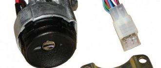
- So check the power to the coil, or rather its presence. For this you will need a multimeter. One terminal is connected to contact B on the coil, and the second goes to ground. Turn on the ignition. If there is no voltage, the culprit is the ignition switch.
- You can start the engine in emergency mode. To do this, the plus from the battery is thrown onto contact B of the coil.
If there is voltage but there is no spark, check whether the primary winding is intact. To do this, the side low-voltage wires are disconnected from the coil and resistance measurements are taken with a multimeter. Then the secondary winding is checked.
We will tell you about this procedure in more detail.
Multimeter for testing
Video “Visual instructions for diagnosing short circuits at home”
Universal instructions for checking short circuits with your own hands using a multimeter are shown in the video below (author - Alexey Romanov).
One of the reasons for problems with a spark in the internal combustion engine on a VAZ 2109 is a malfunction of the ignition coil (IC). To accurately diagnose a malfunction, you need to know the design of the unit, be able to check it and, if necessary, install a new product.
Coil design features
This unit is designed to convert low on-board voltage (12 V) into high voltage (15-30 thousand V), which is supplied to the spark plugs to ignite the fuel assemblies in the engine cylinders. The impulse is transmitted through high voltage wires.
Purpose, principle of operation of the ignition coil
The device is the most conservative part in a gasoline internal combustion engine. Its prototype was invented in Germany by the engineer Ruhmkorff in the mid-nineteenth century. It replaced magnetos in automobile engines in the early 20th century.
The main purpose of the device is to convert low-voltage electrical pulses with an amplitude of about 12 Volts (vehicle on-board voltage) into high-voltage pulses with an amplitude of more than 15,000 Volts. High voltage is necessary to break down the working area of the spark plug.
According to the type of design and ignition circuit, the coils are classified:
- single;
- double (triple, four-block);
- individual.
Ignition coil design
Single devices are used in systems with an ignition distributor. Twins are used in four-cylinder internal combustion engines without a distributor. One part forms a high-voltage pulse to the 1st and 4th cylinders, the second serves the 2nd and 3rd. Triple and quad coils are sometimes used in six-cylinder and eight-cylinder engines, respectively. Individual coils are widely used in modern cars. They are installed on each spark plug individually. A custom spark plug coil has a number of advantages over conventional ones:
- failure of one of the devices does not lead to a complete stop of the engine;
- it is easier to organize an electronic control scheme;
- the absence of a mechanical ignition distributor makes the system more reliable;
- distribution of pulse load reduces currents and increases service life;
- it is easier to identify a faulty device, which is easily done by computer diagnostics;
- Most individual coils have a pulse amplifier installed; it is controlled by low signal currents, which reduces electrical interference and increases the reliability of electrical equipment.
By type of control they are divided into:
- contact;
- electronic;
- with built-in switch (pulse amplifier).
In the ignition contact bobbins, a low-voltage pulse is generated by a chopper. When the primary circuit is switched by a breaker, an electromotive force pulse is induced in the primary circuit. The device is an autotransformer that increases the pulse amplitude N times, where N is the transformation coefficient equal to the ratio of the number of turns in the secondary to the primary winding. The transformation ratio of contact devices exceeds 1000.
Contactless systems use electronic coils. Their transformation ratio is higher and they form a stable spark. During repairs, contact and non-contact devices cannot be interchanged.
A built-in switch is installed on most individual coils, often installed on dual coils. Their disadvantage is a higher probability of failure due to the presence of electronic components.
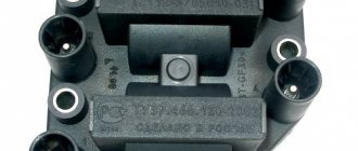
Ignition module for injection engine of VAZ 2108, 2109, 21099 cars
The ignition module on the injection engine of VAZ 2108, 2109, 21099 cars is part of the ignition system.
Purpose of the ignition module
The ignition module on VAZ 2108, 2109, 21099 cars is designed to create high-voltage voltage on the spark plugs at a certain moment.
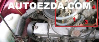
Location by car
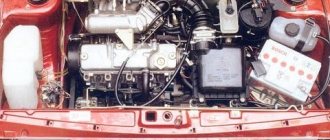
On the 2111 engine of VAZ 2108, 2109, 21099 cars, the ignition module is installed on a special bracket mounted on the front of the cylinder block on the gearbox side.
Ignition module design
The ignition module consists of a housing, inside of which there are two two-terminal ignition coils and a two-channel switch (two electronic units). The housing has four ignition coil terminals, which are connected to the spark plugs in a certain order. The wires for the first and fourth cylinders are connected to the two terminals of one winding, and the wires for the second and third cylinders are connected to the two terminals of the other winding. Therefore, a spark jumps in two cylinders at once (on the compression stroke - working and on the exhaust stroke - idle).
The current supply and control wires from the control unit are connected to the module through a connecting block.
Operating principle of the ignition module
The control unit of the ECM system receives a signal from the crankshaft position sensor about the position of the engine crankshaft and its rotation speed, from temperature sensors and mass air flow sensors information about the condition of the engine and the load on it. After processing the signals, it calculates the ignition timing and sends a command to the ignition module to fire the first or second pair of coils. The ignition module generates high-voltage pulses and supplies them through high-voltage wires to the spark plugs of either 1-4 or 2-3 engine cylinders.
Symptoms of malfunction
More often than not, the bobbin does not suddenly fail. This is usually preceded by a number of warning symptoms.
The main symptoms of a faulty ignition coil:
- misfires in one or more cylinders, they can be determined using a scanner by the presence of the “triple” effect of the engine;
- the appearance of “breakdown tracks” on the housing can be determined visually when starting the engine in the dark;
- the occurrence of cracks and chips in the dielectric zone;
- overheating of the structure;
- burning of rubber tips of high-voltage wires;
- oiling, contamination.
If the above symptoms appear, you should consider purchasing a replacement device. You can't stand by and watch an ignition coil die. In the event of a sudden coil failure, further independent movement will be impossible (unless you have individual coils installed).
Ignition coils
Causes of ignition coil failure
Let's look at the reasons why the ignition coil fails.
Natural wear and tear
Like all electrical and electronic units, the reel has a certain trouble-free operation life. The average service life of ignition coils is approximately seven to ten years of operation or 150,000 - 200,000 thousand mileage. The device is operated in extreme conditions with large differences in temperature, humidity, and the possibility of ingress of moisture, dirt, and foreign liquids. In this case, large currents flow through the primary winding, and a high-voltage pulse is formed in the secondary winding.
Electrical breakdown
Let's figure out why the ignition coil breaks. Firstly, over time, as a result of high temperature changes, the dielectric insulation cracks, and salty moisture, which is a conductor, can enter microcracks. For voltages of more than 15,000 volts generated in the secondary winding, even pure undistilled water acts as a conductor. Secondly, during operation, the physical properties of the dielectric and rubber insulation of the tips of high-voltage wires, especially those of dubious production, change. High-voltage breakdown can be caused by the installation of non-standard high-voltage wires in which there is no distributed current-limiting resistance. A breakdown can occur as a result of severe contamination or waterlogging. Even in the event of a single breakdown, irreversible changes occur in the structure; further operation is not recommended.
Symptoms of a problem
The main signs of ignition coil failure are lack of ignition. If it is a single device with a distributor, then in all cylinders; if it is a double or single device, then in those served by it. The absence of a spark is not necessarily a 100% sign of a faulty coil. Perhaps the limiting resistor has burned out, the spark plug is faulty, the high-voltage wire has broken, or there is a malfunction in the ignition system. A comprehensive fault diagnosis is required.
Visual signs that the ignition coil is not working:
- the presence of “breakdown tracks”, oxides on the coil;
- change in dielectric color;
- burning of contacts and connectors;
- traces of overheating on the body;
- increased pollution.
Recent comments
- Mechanik on Carburetor starting device 2108, 21081, 21083 Solex Check the fuel level in the carburetor float chamber. Plus check if the fuel pump is pumping.
- Boris on Carburetor starter 2108, 21081, 21083 Solex After gas does not work on gasoline. The engine starts for 2-3 seconds and stalls. Half a minute later the same thing.
- Boris on Carburetor starter 2108, 21081, 21083 Solex engine starts but stalls after 2-3 seconds. after 0.5 minutes the same thing
- Andrey on Replacing thresholds on a VAZ 2108 Thank you, useful article. I also have to change the threshold on the eighth road.
How to identify a faulty ignition coil
The procedure for checking the serviceability of the coil depends on how many ignition coils are in the car. If your car has individual ignition coils, in order to identify the faulty one with a high degree of probability, you can swap the supposedly faulty and known-good coils. If, as a result of this replacement, a spark appears in the cylinder in which there was no spark, and disappears in the other, therefore, the bobbin is truly faulty. In the same way, you can check dual and block coils, but you will have to modify the circuit, which is not always convenient.
How to determine which ignition coil is not working without making changes to the electrical circuit
To do this, you need to stock up on thick dielectric gloves and a dry rubber mat. The use of only ordinary dielectric gloves is unacceptable: they can withstand a breakdown voltage of 6300 Volts; the voltage applied to the candle is approximately three times higher.
If your car has two or more ignition coils, if one of them malfunctions, the car should start, but struggle a lot. By removing the tips of the high-voltage wires of the spark plugs or connectors from individual coils one by one, the stability of the engine is assessed. If the internal combustion engine has not changed its operation as a result of removing the connector, then there is no spark in this cylinder. If the engine starts to shake even more, or stalls altogether, there is a spark, the bobbin is faulty, or it is not receiving impulses or power.
High voltage arrester
Multimeter
If the car engine does not start at all and does not catch, you can evaluate the serviceability of the coil using the parametric method. For this you will need a multimeter. An ordinary coil like the Zhiguli one can be ringed without difficulty. To do this, first set the multimeter’s measurement limit to the resistance measurement mode of 200 Ohms or “diode, continuity” and measure the resistance between the coil terminals + and K. The resistance should be in the range from 0.2 to 1.0 Ohms. Please note that during measurement at this limit a small error may appear, which will slightly increase the multimeter readings. Then switch the multimeter mode to the limit of 20 kOhm and measure the resistance value of the second winding (between terminal K and the copper tip into which the high-voltage wire is inserted). The resistance should be in the range of 1 kilo ohm to 3 kilo ohms (2000 - 3000 ohms).
It is impossible to check a coil with a built-in pulse amplifier using this method, since the lead of the primary winding is not connected to its terminals. A common malfunction of individual devices is breakdown of the limiting resistor. It is located under the rubber extension of the reel structure, which is easily removed. The resistor should be removed and its resistance measured with a multimeter at a limit of 20 kilo-ohms. It should be between 1 and 3 kilo-ohms.
Megaohmmeter
You can also evaluate the insulation resistance if you have a megohmmeter at your disposal. The insulation resistance (between the copper contact into which the high-voltage spark plug wire is inserted and the housing) must be more than 300 megaohms. This measurement is of an evaluative nature. If the resistance is less, the coil is probably faulty, if the resistance is more, it is probably working, it is impossible to judge more precisely.
A simple three-terminal coil can be checked “by weight”, that is, by assembling a simple circuit. The +12V voltage from the battery is connected to the + terminal, a high-voltage wire is inserted into the connector, and a spark plug is connected to the second terminal. The spark plug body is connected to the metal part of the engine. Next, connect a stranded insulated conductor with a cross-section of 2 sq. mm to contact K. Holding the insulation, briefly touch the metal part of the engine with the other stripped end of the wire. A spark should jump where the engine touches and through the spark plug. In electronic coils, the spark from the spark plug is less intense. You cannot experiment with this method for a long time.
Some specialized service stations have self-made inspection stands. Their use requires special methods.
Verification procedure
If you detect one or more signs of “dying” of the coil or if it is impossible to start the engine, you should definitely check its performance.
This is necessary in order to find out what nature of the breakdown occurred, and, therefore, begin to eliminate it. Can this be done without instruments? Unfortunately no. Unless you immediately replace the coil with a known good one. At the very least, a regular multimeter will suffice. Such a tester must be kept in the car - its cost is almost symbolic.
In general, verification is relatively easy. It is enough to follow the steps described below, and even a completely inexperienced car enthusiast can handle it.
First of all, you need to inspect the ignition unit itself. If the engine does not start at all, then you need to find out if there is a spark. You need to do this:
- disconnect the main wire from the distributor (located in the center);
- connect a candle to it;
- holding it with pliers, apply it to the motor housing or to the breaker;
- turn on the ignition.
If there is no spark, there is only one conclusion - failure in the coil. Next, you need to find out whether electricity is supplied to it.
The check is carried out with a multimeter. One of its probes is applied to terminal “B” on the coil, the second to ground. If there is no voltage after turning on the ignition, the fault is looked for directly in the lock.
In addition, it is also possible to power the coil using an emergency circuit. Here the wire from the positive terminal of the battery is connected to contact “B”. In this situation, you can be absolutely sure that voltage is supplied. However, when these actions did not lead to a spark, you will have to test the primary winding for integrity.
- the wiring located on its sides is disconnected (they are low-voltage);
- the multimeter is set to Ohms and the resistance is measured;
- The secondary winding is also ringed in the same way.