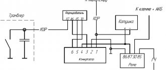
Connecting high-voltage wires ZMZ 405, ZMZ 406
ZMZ carburetor and Euro-2 engines are equipped with a DIS (Double Ignition System) ignition system.
The DIS system uses ignition coils with two high-voltage wires. Each coil operates a corresponding pair of cylinders.
The first coil works with 1 and 4 cylinders, the second coil works with 2 and 3 cylinders.
How to connect the ignition coils?
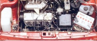
The ignition coil of cylinders 1 and 4 is located closer to the intake manifold, the coil of cylinders 2 and 3 is closer to the exhaust manifold.
Low-voltage coil wires must be connected to the coil in pairs. The pair of wires for coil 1-4 is slightly shorter than the pair of wires for coil 2-3.
Within the pair, it does not matter which contact is connected to which wire - the coils are non-polar. Also, within the pair, it does not matter which high-voltage wire goes to which cylinder.
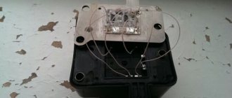
Let's look at an example (see photo)
Coil 1 control (cylinders 1 and 4) – green and yellow wires. This pair connects strictly to the coil of cylinders 1 and 4!
Low voltage circuit - polarity is not important - can be connected:
Option 1: The top coil contact is yellow, the bottom contact is green.
Option 2: The top coil contact is green, the bottom contact is yellow.
High voltage outputs – polarity is not important – can be connected:
Option 1: Top outlet for cylinder 1, bottom outlet for cylinder 4.
Option 2: Top outlet for cylinder 4, bottom outlet for cylinder 1.
Coil 2 control (cylinders 2 and 3) – blue and yellow wires. This pair is connected strictly to the coil of cylinders 2 and 3! Further - similar to pair 1-4 - the polarity within the pair is not important.
The determining factor when connecting pairs of low-voltage and high-voltage wires to the corresponding ignition coil is the correctness of their routing. The wires should not be too tight, bent too much, and should not rub against fixed parts of the engine or other wires.
Another article about high-voltage wires ZMZ 405, 406 - read so as not to repeat this mistake.
Source
Malfunction of high-voltage wires: symptoms and consequences
The general symptoms are similar to problems with spark plugs (unless the injector is to blame for the failure), so before checking the high-voltage wires, make sure that the remaining engine components are in good working order.
- Problems with starting - the spark plugs do not receive enough voltage. This could be a broken wire or corrosion of the tip contacts. The malfunction is typical for an engine that is not warmed up;
- The engine “shoots” at start; If it starts, it runs unevenly, with increased vibrations. The order of connecting high-voltage wires is violated;
- Ragged operation at idle. The connection with the candle is lost due to vibration;
- Violation of CO emission standards. The problem is accompanied by periodic tripping of the motor. One of the cylinders misfires and the fuel does not burn completely;
- Interference on the multimedia system: the character changes when the crankshaft speed changes. In the slang of car enthusiasts, high-voltage car wires are “sewn to ground.” Multiple discharges on the motor housing create “thunderstorm” interference;
- Smell of ozone under the hood. The reason is the same as in the previous paragraph: high-voltage wires penetrate the housing.
Connecting high-voltage wires ZMZ 405, ZMZ 406
ZMZ carburetor and Euro-2 engines are equipped with a DIS (Double Ignition System) ignition system.
The DIS system uses ignition coils with two high-voltage wires. Each coil operates a corresponding pair of cylinders.
The first coil works with 1 and 4 cylinders, the second coil works with 2 and 3 cylinders.
How to connect the ignition coils?
The ignition coil of cylinders 1 and 4 is located closer to the intake manifold, the coil of cylinders 2 and 3 is closer to the exhaust manifold.
Low-voltage coil wires must be connected to the coil in pairs. The pair of wires for coil 1-4 is slightly shorter than the pair of wires for coil 2-3.
Within the pair, it does not matter which contact is connected to which wire - the coils are non-polar. Also, within the pair, it does not matter which high-voltage wire goes to which cylinder.
Let's look at an example (see photo)
Coil 1 control (cylinders 1 and 4) – green and yellow wires. This pair connects strictly to the coil of cylinders 1 and 4!
Low voltage circuit - polarity is not important - can be connected:
Option 1: The top coil contact is yellow, the bottom contact is green.
Option 2: The top coil contact is green, the bottom contact is yellow.
High voltage outputs – polarity is not important – can be connected:
Option 1: Top outlet for cylinder 1, bottom outlet for cylinder 4.
Option 2: Top outlet for cylinder 4, bottom outlet for cylinder 1.
Coil 2 control (cylinders 2 and 3) – blue and yellow wires. This pair is connected strictly to the coil of cylinders 2 and 3! Further - similar to pair 1-4 - the polarity within the pair is not important.
The determining factor when connecting pairs of low-voltage and high-voltage wires to the corresponding ignition coil is the correctness of their routing. The wires should not be too tight, bent too much, and should not rub against fixed parts of the engine or other wires.
Another article about high-voltage wires ZMZ 405, 406 - read so as not to repeat this mistake.
High-voltage wire tip - what is it for?
Connection in the traditional way is not possible. The tips of the candle should be easily removable, but provide reliable contact. As a rule, the caps are made of a solid dielectric, although there are exceptions. Rubber adheres better to the walls of the spark plug well and ensures tightness. However, this material is subject to wear and tear. Plastic dielectric is more durable, but moisture can condense underneath it. Which material to choose is decided by the manufacturer depending on the design of the cylinder head.
There is one wire coming from the ignition coil; distribution to the spark plugs occurs on the distributor. Depending on the engine design, the four-cylinder version has up to ten tips. Just like the main wires, caps can cause breakdown or loss of contact. Water gets under them, the material cracks, and a spark “pierces” the spark plug insulator.
Parameters of the main components of the ZMZ-406 engine
The engine is gasoline, four-cylinder, in-line with an integrated microprocessor control system for fuel injection and ignition.
The ZMZ-406 engine is installed on GAZ-3110 Volga passenger cars and GAZ-3302 Gazelle trucks.
The main design features of the ZMZ-406 engine of the GAZ-3110 Volga, Gazelle GAZ-3302 cars are the upper (in the cylinder head) arrangement of two camshafts with the installation of four valves per cylinder (two inlet and two exhaust).
Increasing the compression ratio to 9.3 (instead of 8.2 on the 402 model engine) due to a combustion chamber with a central spark plug, using a system of distributed (alternately in accordance with the order of operation of the cylinders) fuel injection into the intake pipe using electromagnetic injectors (instead of carburetor supply) .
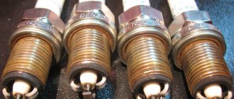
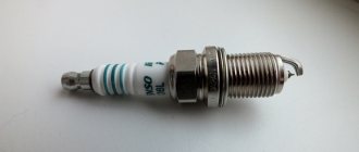
Spark plugs used for Gazelle with ZMZ-405 and 406 engines
So, this car uses standard-looking spark plugs with a long threaded part, and they consist of a central electrode, a ceramic insulator, a skirt and a side electrode.
This is a simplified description of the design, because a modern spark plug also includes gaskets and O-rings, resistors, etc.
In general, it can consist of quite a few elements.
The manufacturer provides for the use of spark plugs with the domestic marking A14VR on modern Gazelle engines (models ZMZ-405 Euro 2 and ZMZ-406).
It is also possible to use A14DVR models and their analogues, both domestic and foreign.
A special feature of these spark plugs is the gap between the electrodes, which is 0.8 mm. But this is only an external feature. The main thing is the heat number.
This indicator is a characteristic of the thermal properties of a given element. To put it simply, it is the ability to heat up to critical temperatures under different thermal loads.
A14 spark plugs, which are recommended for use on Gazelle engines, are intended for use on low-power engines with a low compression ratio.
If we take the spark plugs recommended for installation on the power units of VAZ cars, then they are not very suitable for Gazelles, since their heat rating is 17, and their thermal gap between the electrodes is 1 mm.
Therefore, when using them, omissions are likely, due to which the stable operation of the power plant will be disrupted.
As far as foreign manufacturers are concerned, they do not have a distinction based on heat rating, so when purchasing them, it is better to find out in advance the markings of candles that correspond to domestic ones.
Below are just some of the most popular foreign manufacturers, the markings of which correspond to the domestic A14BP
and
A14DVR
:
- Bosh – W8D, WR8D;
- Brisk – LR17Y, LR17YC;
- Champion – NR11Y, NR11YC;
- NGK – BPR5E, BPR5ES;
- Denso – W16EXP, W16EXP-U.
Engine Description
Previously, the engine was designed for newfangled power and ignition systems, which were controlled by a microprocessor.
This engine was the first to be equipped with four valves per cylinder, with hydraulic lifters and two camshafts with a double chain drive. An electronic fuel supply system and electronic ignition were also installed.
The four cylinders have an in-line arrangement, a water jacket and controlled fuel injection.
The ZMZ-406 injector runs on A-92 gasoline. Previously, a carburetor version of the 4061 engine was produced, which ran on seventy-sixth gasoline. It had limitations in terms of release.
The unit is unpretentious in maintenance. It has a high degree of reliability. Later, on its basis, ZMZ-405 and 409 units were developed, as well as a diesel version of the engine labeled ZMZ-514.
The disadvantages of the engine include the cumbersome nature of the gas distribution mechanism drive, which is explained by its low quality of workmanship and a number of technological shortcomings.
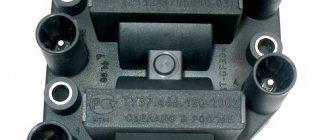
Possible malfunctions of the ignition coil 406.3705
- The fault lamp lights up after the fault is turned on. Self-diagnosis of the unit records fault codes 91…94(98), or 231…234(238), or 241…244(248). Check the serviceability of circuits 27a, 1(27b), 2(27v) ignition coils
- check the serviceability of the ignition coil circuits 1(27b) or 2(27v)
Ignition coil fault codes 406.3705
| See all advertisements in the archive |
| Fault code | Fault name | Definition conditions |
| 091 | Load short circuit in ignition circuit 1 (KZ-1.4) | When the internal combustion engine is running |
| 092 | Load short circuit in ignition circuit 2 (KZ-2,3) | When the internal combustion engine is running |
| 093 | Load short circuit in ignition circuit 3 (KZ-2,3) | When the internal combustion engine is running |
| 094 | Load short circuit in ignition circuit 4 (KZ-1,4) | When the internal combustion engine is running |
| 231 | Open circuit 1 ignition | When the internal combustion engine is running |
| 232 | Open circuit 2 ignition | When the internal combustion engine is running |
| 233 | Open circuit 3 ignition | When the internal combustion engine is running |
| 234 | Open circuit 4 ignition | When the internal combustion engine is running |
| 241 | Short circuit to ground, ignition circuit 1 | When the internal combustion engine is running |
| 242 | Short circuit to ground ignition circuit 2 | When the internal combustion engine is running |
| 243 | Short circuit to ground ignition circuit 3 | When the internal combustion engine is running |
| 244 | Short circuit to ground ignition circuit 4 | When the internal combustion engine is running |
Carburetor engine
The ZMZ-406 carburetor (402nd engine) has been produced since 1996 and has managed to establish itself as a simple and reliable unit. This device develops a power of 110 horsepower. The fuel consumption of a car with this engine often depends on driving style and operating conditions. The power system of the carburetor unit is quite reliable. With timely maintenance and normal operation, using high-quality lubricants and gasoline, it can travel up to 500 thousand kilometers without serious breakdowns. Of course, with the exception of boring the crankshaft, which is necessary for this unit once every 250 thousand kilometers.
Checking high-voltage ignition wires using improvised means
If your car is equipped with an OBD port, you can localize the fault to at least the cylinder number. The most primitive scanner (such as ELM 327) will show misfire or lack of ignition. With any method of identifying a problem area, it is better to test the wires in the removed state. For a complete test, you will need a voltage multiplier and a megohmmeter (to check the insulation). Wires are connected to the high voltage source and laboratory tests are carried out. As a rule, there is no such equipment in the garage, so we will use a multimeter.
The test begins with a visual inspection. There should be no cracks on the insulation, no black points of spark breakdown, the cable should bend with the same force in any place. Tips without oxides or breaks. The caps are intact, with the same thickness of the skirt.
Then we measure the resistance of the high-voltage ignition wires. On all armored cables it should be approximately the same - within 2 kOhm - 10 kOhm. Exactly what value depends on the manufacturer. The denomination can be found in the product passport. It is impossible to replace high-voltage wires with non-standard ones (from another car), their resistance is calculated according to the capabilities of the ignition coil. Faulty ones must be rejected: repair of high-voltage wires inside the insulation is impossible.
Important! Connecting the multimeter probes must have good contact, otherwise you may introduce a high error in the measurement.
Ignition system
On ZMZ-406 engines, ignition is carried out by igniting the fuel mixture using a microprocessor system. For all engine operating modes, the electronics sets the required ignition timing. It also performs the function of adjusting the working process of the forced idle economizer. Due to the operation of this system, the engine is distinguished by its high economic performance, exhaust gas toxicity standards are monitored, the moment of detonation is eliminated and the power of the power unit is increased. On average, a GAZelle car consumes about 8-10 liters of gasoline per 100 kilometers under average loads. However, if you convert it to propane or methane, the “appetite” of the machine almost doubles.
Replacement sequence
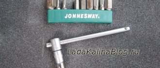
Replacing spark plugs on ZMZ-405 and 406 engines used in Gazelle cars is a fairly simple operation and does not require any special tools.
All you need:
It is better to carry out all work on a cold or sufficiently cooled engine so as not to get burned when removing the spark plugs from the engine.
These elements are located on these engines in the head, access to them is provided through technological holes in the valve cover.
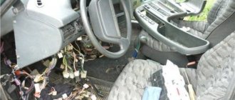
First, the high voltage wires are disconnected from the spark plug tips. It is important to take into account that you cannot pull on the wires themselves, but they must be removed by pressing on the sealing caps.
In the technological holes, the tips are held at the top by rubber plugs.
To remove the tip, you need to pry off this plug with a screwdriver, and then pull the tip itself up.
Before unscrewing the spark plug, you need to carefully inspect the space around it for debris and dirt; if necessary, clean the surface and blow it with a pump or compressor to prevent debris from getting into the cylinders.
Next, the spark plug wrench is put on the spark plug, and by rotating it counterclockwise, it is unscrewed.
You need to immediately inspect it for the presence of an o-ring; if it remains in the seat, remove it with tweezers.
Before installing a new element, you need to check it for the presence of an o-ring, check the gap, and also find out whether the contact nut at the top of the central electrode has been used.
If it is not on the old spark plug, then this nut will also have to be tightened with the new one, otherwise the tip will not fit.
Install the new element in the key, where it will be held by the holder.
Then install it in the seat and tighten it with force, but not too strong, so as not to break the thread.
Then put the tip on it and secure it with a plug. And only after that connect the high voltage wire.
All spark plugs on these engines are changed sequentially - first on the first cylinder, then on the second, etc.
Important to read: Iridium spark plugs, advantages and disadvantages.
Constant monitoring and timely replacement of such seemingly insignificant elements as spark plugs will ensure uninterrupted operation of the engine, easier starting and full power delivery.
Source
Ignition diagnostic mode
When the car ignition is turned on, the ZMZ-406 engine diagnostic system automatically comes into operation (the ZMZ-405 carburetor is no exception). The fact that the electronics are working properly is indicated by a light sensor. It should go out when the engine starts.
If the diode continues to light, this indicates a malfunction of the elements and parts of the electronic ignition system. In this case, the breakdown should be repaired immediately.
Checking high-voltage ignition wires without removing them from the car
This is a primitive but quite effective method. The simplest option is to install a known-good cable and compare the operation of the engine. If the location of the high-voltage wires allows, you can swap them (along with the connector on the distributor), and again read the errors with the scanner. It will indicate a different cylinder number.
Putting a dielectric glove on your hand, you can remove the tips from the spark plugs one by one while the engine is running. When you reach the problem cylinder, the nature of the work will not change.
Definition of breakdown “by eye”. In the dark you can see how the spark “sews” onto the body of the internal combustion engine. You can connect a thick wire to ground and run the bare end along the insulation. You will see the weak point immediately - a spark will strike.
Despite a whole bunch of breakdowns that armored wires can cause, their solution is no more difficult than replacing plugs in a home electrical panel. If a faulty one was identified, a new one was installed. If there is a problem, how to change high-voltage wires on the highway or in an open field (far from stores), remember that the cables do not break suddenly; regular diagnostics will help you not to be caught by surprise.
Injection motor
In terms of technical characteristics and components, an engine with an injection power system is not very different from the carburetor analogue of the 405 model.
With proper operation, this unit is no less reliable and practical than with a carburetor, and in addition has its own advantages:
- Stable idle speed.
- Low level of harmful emissions into the atmosphere.
- The efficiency of the ZMZ-406 injector is much higher than its analogue with a carburetor, since the fuel mixture is supplied in a timely manner and in the right quantity. Accordingly, fuel savings are obvious.
- Improved fuel economy.
- Does not require prolonged engine warm-up in winter.
The only disadvantage of an injection engine is the high cost of repair and maintenance of the system.
What do spark plugs do?
Many car enthusiasts believe that spark plugs are not such significant elements of the ignition system, and nothing really depends on them.
And indeed it may seem so, because they are just an element that converts the voltage supplied from the coil into a spark that ignites the combustible mixture in the cylinder. But it's not that simple.
The quality and rate of combustion of the fuel mixture depends on the quality of the spark that jumps between the electrodes, and this directly affects power performance and fuel economy.
Therefore, if the spark is weak due to an inappropriate gap between the electrodes, or there are any gaps due to damage to the insulator or loss of tightness, then some of the fuel will simply fly out “down the pipe” without performing a useful effect.
Hence the loss of power and inappropriate fuel consumption.
New spark plugs often solve the main problem - lack of spark. But it is important to take into account that different models are produced, designed for certain operating conditions.
Therefore, on some engines a new set of spark plugs of a certain brand may work perfectly, but on another it may produce a weak spark, which will affect the quality of fuel combustion.
Next, we will look at the issue of matching spark plugs for engines installed on Gazelle cars.
Block head
All engine modifications were equipped with one head, which complied with Euro 2 requirements. With the introduction of additional Euro 3 requirements, it was refined and improved. It is not interchangeable with the previous model.
The new head does not have idle system grooves; now their functions are assigned to an electronically controlled throttle. The front wall of the part is equipped with holes for attaching the protective chain cover, and on the left side there are ebbs for mounting the intake system receiver brackets. The part has pressed cast iron inserts and valve guides. The latter do not require periodic adjustment, since they are driven by cylindrical pushers with hydraulic compensators. The modernized ZMZ-406 head has decreased in weight by 1.3 kilograms. When installing it on the engine, use a metal multilayer head gasket.
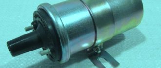
Technical characteristics of ignition coil 406.3705
- The power supply voltage is 6-18 volts.
- Primary winding resistance: 0.35±0.02Ohm.
- Secondary winding resistance: 13±0.2 Ohm.
- Inductance of the primary winding at a frequency of 100Hz: 2.22±0.2mH.
- Output voltage: not less than 24 kV.
- Switching current in the primary circuit: no more than 7.5 A.
- Spark discharge energy: not less than 50 mJ.
- Discharge duration: not less than 2.2 ms.
- Current switching frequency in the primary circuit: 1…133Hz.
- Reel weight: 0.65 kg.
- Width: 0.08 m.
- Height: 0.06 m.
- Length: 0.08 m.
- To connect the ignition coil to the spark plugs, high-voltage wires with distributed noise suppression resistance must be used. The total resistance of the high-voltage wire, taking into account the noise suppression resistor in the tip, should be within 6 kOhm.
Camshaft
The ZMZ-406 camshaft is made by casting cast iron, followed by processing and hardening. The shafts are driven by a chain transmission. The engine has two shafts, the cam profiles of which are the same size.
The axial displacement of the cams is one millimeter relative to the hydraulic pushers. This factor promotes the rotation of hydraulic drive elements when the engine is running, which significantly affects the wear of the working surface of the pusher and makes it uniform.
The chain drive of the shafts has hydraulic tensioners that operate from oil pressure in the lubrication system. The parts act on the chain directly through plastic shoes that are attached to the axles. After modernization, on ZMZ-406 engines, sprockets were used instead of shoes to increase practicality and durability. The latter are fixed on rotary arms. The sprocket mounting axles are interchangeable with the shoe axles. Instead of an extension of the upper chain tension shoe axis, they began to use a spacer, which is fastened to the block with bolts.
The ZMZ-406 engine is equipped with camshaft drive chains. It is not possible to replace them with chains that were installed on earlier versions of motors.
Basic aspects of ignition installation
The main aspects to consider when installing the ignition by marks:
- First, you need to dismantle the front cylinder head cover; to do this, you need to unscrew four 12-point screws. In some engine modifications, dismantling also involves removing the fuel pump.
- Then the upper hydraulic tensioner located in the head is dismantled; to do this, two screws securing the cover are unscrewed.
- Next, the chain stabilizers are removed - the middle one, as well as the top one; for this, the two screws that secure them are unscrewed.
- After this, the camshaft sprockets are dismantled. The shafts themselves need to be fixed using a 27 key, while simultaneously unscrewing the screws that secure them. In modifications of engines 4063.10, the camshaft sprocket is removed along with the fuel pump drive eccentric.
- In accordance with the jig installed on the sprocket, six holes should be drilled in each of them. Their angular displacements should be 2, 30, 5, 00, 7 and 30 degrees from the set position of the factory hole, which is located along the axis of symmetry.
- If, when adjusting the phases, it is necessary to turn the camshaft clockwise, the sprocket itself should be mounted on one of the additional holes with a positive offset. It is located to the right of the standard hole.
Pistons
They are cast from aluminum alloy and have grooves for two compression rings and one oil scraper ring. During operation, the piston crown is cooled by oil through an oil nipple in the upper end of the connecting rod.
The spherical working surface of the upper compression ring has a layer of chrome coating, which facilitates better grinding of the ring. The second element is coated with a layer of tin. The oil scraper ring is of a combined type; it consists of an expander and two steel discs. The piston is attached to the connecting rod using a pin fixed to two corkscrew rings.
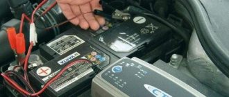
How to check short circuit?
How to check the short circuit yourself:
- First, disconnect the power cable from the negative terminal of the battery and turn off the ignition.
- Then open the hood and disconnect the two high-voltage cables from the product. Unscrew the bolts and also dismantle the bar along with the product. The second short circuit is dismantled in a similar way.
- The diagnostic procedure itself is carried out using an ohmmeter; its probes are connected instead of disconnected wires. After connecting the probes, it is necessary to measure the resistance level. If the product is operational and in good working order, then the resistance level should be about 0.4-0.5 Ohm.
- To obtain more accurate diagnostic data, you can also short-circuit the tester probes, and then perform resistance diagnostics again. In particular, you are now interested in the secondary winding of the device. If the device is operational, then the resulting value should be around 5-7 kOhm. If the diagnostics showed different values, this indicates that the short circuit needs to be replaced.
Photo gallery “Short circuit diagnostics”
Crankshaft
Cast from cast iron with subsequent processing and hardening of the surface of the journals with high frequency currents. It is installed in the block on five main bearings.
The movement of the crankshaft according to the axis is limited by corkscrew half-rings, which are located in the flow grooves of the support and the cover of the third main bearing. There are eight counterweights on the shaft. A flywheel is attached to the rear of the shaft, in the hole of which a spacer sleeve and a rolling bearing of the gearbox input shaft are pressed.
Checking the spark plugs
When inspecting spark plugs, it is advisable to check their functionality. This is best done on a special stand, which checks sparking under different pressures, simulating the operation of the cylinder.
But you can check it in a simple way, without using a stand. The unscrewed spark plug is connected to the tip of the high voltage wire and the skirt touches the massaged element, often the valve mechanism cover.
It is important that the surface to which the skirt is pressed is not painted.
Next, the ignition is turned on and the crankshaft is cranked several times by the starter. In this case, a bright and powerful purple spark should jump between the electrodes. Moreover, the intensity of the spark should be high and not interrupted.
A weak and faded spark may indicate problems with the ignition system or with the spark plug itself. Missing sparks are also unacceptable.
Oil
The ZMZ-406 power plant is equipped with a combined lubrication system. Under the influence of pressure, the process of lubrication of the piston pins, connecting rod and main bearings of the crankshaft occurs, the support points of the camshafts, the hydraulic valve drive, the intermediate shaft and the driven gear of the oil pump are lubricated. All other parts and elements of the motor are lubricated by spraying oil.
Closed crankcase ventilation with forced exhaust of gases.
Source
CONNECTION FEATURES
The order of connecting high-voltage wires must be strictly sequential, since each cylinder of the engine corresponds to a specific socket on the ignition module. Considering that there is a numbering of the sockets on the ignition module body, the risk of confusing anything is minimal.
The procedure for connecting high-voltage wires of the VAZ 2114 injection type depends on the year of manufacture of your car. Fourteeners before 2004 had 4-pin ignition modules installed, and cars after 2004 had 3-pin coils.
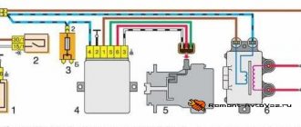
The connection diagram for VAZ 2114 high-voltage wires to the ignition module (until 2004) is as follows:
Connection diagram for VAZ-2114 with ignition coils (after 2004):
In the pictures you can see the numbers of the landing slots. Each number must have a corresponding cylinder connected to it (cylinder numbering is counted from left to right).
To correctly install high-voltage wires on the VAZ 2114, follow the following algorithm of actions:
- Turn off the ignition. Open the hood and remove the power terminals from the battery;
- We remove the old GDPs from the mounting sockets on the module and cylinders;
- We remember the location of the high-voltage wires of the VAZ 2114 and connect new GDPs according to the diagram. Before replacing, it would not be amiss to draw this very diagram by hand on paper so as not to confuse anything;
- We connect power to the battery and, to check whether we did everything correctly, start the engine.