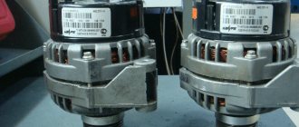
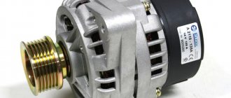
Lada Kalina cars are equipped with generators of two brands - 5132.3771 or 9402.3701-06. The standard Kalina generator is a three-phase alternating current device, which has a built-in rectifier unit and an electronic voltage regulator.
There are very different reviews regarding the quality and reliability of the devices with which these cars are equipped during factory assembly. If the unit fails, you can replace or repair it yourself.
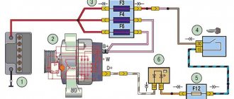
General diagram of electrical equipment of VAZ 1118
1 — block headlight; 2 — windshield wiper gear motor; 3 - generator; 4 - battery; 5 - starter; 6 — sound signal; 7 — hood open sensor; 8 — power window switch for the right front door; 9 — motor-reducer for window lifter of the right front door; 10 — electric pump for windshield washer; 11 — connecting blocks of wires for connecting the right (front) speaker of the audio system; 12 — electric drive for locking the lock of the right front door with an open door sensor; 13 — ambient air temperature sensor; 14 — connecting block of the wiring harness for connection to the engine control system harness; 15 — electric drive for locking the left front door lock (with an open door sensor and a central locking switch); 16 — sensor of insufficient brake fluid level; 17 — connecting blocks of wires for connecting the left (front) speaker of the audio system; 18 — right front door power window switch (installed on the driver’s door); 19 — left front door power window switch; 20 — central locking switch; 21 — motor-reducer for window lifter of the right front door; 22 — remote control unit; 23 — immobilizer control unit (APS-6); 24 — mounting block; 25 — instrument panel; 26 — right side turn signal; 27 — glove box lighting lamp; 28 — switch for the glove compartment lighting lamp; 29 — brake signal switch; 30 — ignition switch (lock); 31 — lighting control unit; 32 — steering column switches; 33 — left side direction indicator; 34 — connecting blocks of wires for connecting the left (rear) speaker of the audio system; 35 — electric drive for locking the left (rear) door with an open door sensor; 36 — electric heater fan; 37 — additional heater resistor; 38 — heater switch; 39 — alarm switch; 40 — reverse lock solenoid switch; 41 — rear window heating switch; 42 — connecting blocks of wires for connecting the right (rear) speaker of the audio system; 43 — electric drive for locking the right rear door lock (with a door open sensor); 44 — fuel module of the engine control system; 45 — reverse light switch; 46 — parking brake warning lamp switch; 47 — cigarette lighter; 48 — reverse lock solenoid; 49 — connecting blocks of wires for connecting the head unit of the audio system; 50 — backlight lamps on the trim of the center console of the instrument panel; 51 — electric power steering control unit; 52 — interior lamp; 53 — rear light; 54 — block for connecting the electric drive for locking the trunk lid lock*; 55 — luggage compartment lid open sensor; 56 — license plate lights; 57 — additional brake light; 58 — rear window heating element; 59 — luggage compartment lighting lamp.
Main process
Replacing the generator in the case of Kalina with an 8-valve or 16-valve engine involves performing the following steps:
- First of all, you will need to install the car on the repair site and fix the position of its wheels using wheel chocks. It is also necessary to turn off the engine and disconnect the terminals from the battery to ensure the safety of the work being carried out.
- After this, you need to loosen the belt tensioner roller, which fixes the position of the generator. To do this, you will need to unscrew the fasteners and dismantle them.
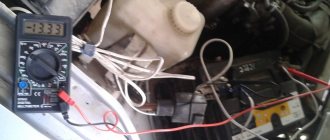
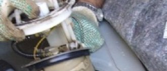
- The next step is to disconnect the plug secured by a plastic latch. To remove it, you need to lightly press it and pull it to the side. If everything is done correctly, the plug can be removed without problems.
- You will also need to remove the wire terminals located under the protective cap. Therefore, the car owner will first need to dismantle the protective cap by prying it off, and only then remove the terminals.
- The next step is to unscrew the nut securing the upper part of the generator. It is considered the most complex process among those listed, and it is better to familiarize yourself with the structure of the car in advance so that no problems arise. To make the nut give way quickly, you can move it with a wrench and then work it with a ratchet handle. Finally, all that remains is to lightly tap the protruding bolt so that it moves, after which you can remove it from the reverse side.
- Once the top bolt of the generator is removed, you can proceed to the bottom one. The actions are the same - a knob, a ratchet handle, a light knock and dismantling. However, in this case, it is recommended to hold the nut on the reverse side so that it does not turn.
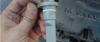
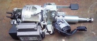
- Next, you should begin dismantling the rod. This should be done carefully and carefully, since there are bearings and bushings inside. They will need to be held so that they do not fall and get lost.
The final step will be to dismantle the generator, clean the internal space of dirt, rust, possible traces of oil, and install a new unit - a standard generator or its equivalent.
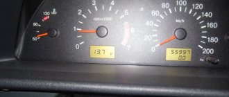
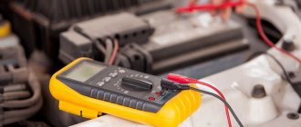
You can check the functionality of the generator with a multimeter by connecting it to the battery terminals. The voltage reading should not be less than 13.4 volts.
The pitfall when replacing a Lada Kalina generator with air conditioning is its changed position, so you will have to approach it from the other side.
Thus, in order not to have to change the generator frequently, it is recommended to regularly inspect the technical condition of the car and, if necessary, repair certain parts, devices, and systems. Undoubtedly, repairs will cost the owner of Kalina somewhat less than buying new spare parts and entire units.
Ignition system diagram Lada Kalina Lux
1 – oil pressure warning lamp sensor;
2 – coolant temperature indicator sensor; 3 – additional fuse block; 4 – fuses for the electric fan of the engine cooling system; 5 – electric fuel pump relay; 6 – relay for the electric fan of the engine cooling system; 7 – ignition relay; 8 – relay 2 of the electric fan of the engine cooling system; 9 – relay 3 of the electric fan of the engine cooling system; 10 – electric fan of the engine cooling system; 11 – throttle position sensor; 12 – idle speed regulator; 13 – coolant temperature sensor; 14 – diagnostic block; 15 – ignition system harness block to the instrument panel harness block; 16 – solenoid valve for purge of the adsorber; 17 – speed sensor; 18 – ignition system harness block to instrument panel harness block 2; 19 – mass air flow sensor; 20 – crankshaft position sensor; 21 – oxygen sensor; 22 – controller; 23 – rough road sensor; 24 – diagnostic oxygen sensor; 25 – ignition coil harness block to the ignition system harness block; 26 – ignition coils: 27 – ignition system harness block to the ignition coil harness block; 28 – spark plugs; 29 – nozzles; 30 – resistor; 31 – air conditioning system pressure sensor; 32 – blocks of the ignition system harness and injector wiring harness; 33 – phase sensor; 34 – knock sensor. Ignition system wiring harness -11184-3724026-10. Ignition coil wiring harness -1118-3724148-00. Injector wiring harness -11184-3724036. A – to the “plus” terminal of the battery.
On Kalina cars, the generator is three-phase and produces alternating current. There is no need to go into too much theory; an ordinary motorist only needs to know how to independently diagnose and repair the installation. This means installing the generator and voltage regulator directly. The fact is that at the output of the power windings the voltage jumps in the range of 10-30 V, and to power the entire on-board network you need 12 V. The first step is to rectify the voltage and then stabilize it.
Lada Kalina dashboard diagram
1,2,3,4 – blocks of the instrument panel wiring harness to the blocks of the rear wiring harness; 5,6 – blocks of the instrument panel wiring harness to the blocks of the front wiring harness; 7 – block of the instrument panel wiring harness to the block of the wiring harness 8 – block of the instrument panel wiring harness to the block of the front wiring harness; 9 – lighting control module; 10 – ignition switch; 11 – on-board computer mode switch; 12 – windshield wiper switch; 13 – sound signal switch; 14 – light signaling switch; 15 – instrument cluster; 16 – evaporator temperature sensor; 17 – interior air temperature sensor; 18 – air conditioner switch; 19 – controller of the automatic climate control system; 20 – heater damper gearmotor; 21 – rear window heating switch; 22 – alarm switch; 23 – brake signal switch; 24 – cigarette lighter; 25 – electric amplifier control unit; 26,27 – blocks of the instrument panel wiring harness to the radio; 28 – backlight lamp for the heater control panel; 29 – illuminator; 30 – mounting block: 31 – heater electric motor switch; 32 – heater electric motor; 33 – additional resistance of the heater electric motor; 34 – glove box lighting; 35 – glove box lighting switch; 36 – control unit of the APS-6 automobile anti-theft system; 37 – driver airbag module; 38 – passenger airbag module; 39,40 – blocks of the instrument panel wiring harness to the blocks of the ignition system wiring harness.
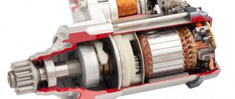
Operating principle
The basic principle of operation of the generator is as follows: a three-phase alternating current is induced in the stator winding, which is converted into direct current using a rectifier unit attached to the cover of the device. On the cover there is a unit consisting of an electronic voltage regulator and a brush holder. The rotor rotates from the crankshaft of the car engine via a serpentine belt.
The Lada Kalina generator has the following characteristics:
- maximum output current - 85-90 A;
- voltage - 14.4-15.1 V;
- engine-generator gear ratio - 1:2.4;
- direction of rotation is right.
4 bolts secure the stator and covers of the device. The covers contain bearings in which the rotor shaft rotates. The rear bearing is located on the rotor shaft; it is mounted in the rear cover with a small gap. The front bearing, which slides along the rotor shaft, is installed in the front cover with a slight interference fit and covered with a pressure plate. The device is covered at the back by a plastic casing.