April 13, 2016 Lada.Online 210 384 4
Depending on the year of manufacture, different types of instrument panels were installed on the domestic SUV. Until about 1998, Niva 4x4s were equipped with instrument clusters made in Hungary, and after Avtopribor LLC (Vladimir and Podolsk). Let's look at the features of these panels in the diagrams.
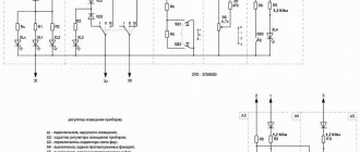
Niva 4x4 instrument panel diagrams
Schematic electrical diagrams, connecting devices and pinout of connectors
1 – plug connector block with conditional numbering of plugs; 2 – tachometer; 3 – voltage stabilizer; 4 – instrument cluster lighting lamp; 5 – coolant temperature indicator; 6 – fuel level indicator; 7 – resistor 470 Ohm, 0.25 W; 8 – resistor 36 Ohm, 5 W; 9 – warning lamp of the toxicity reduction system;
10 – control lamp for heated rear window; 11 – fog light indicator lamp; 12 – control lamp for high beam headlights; 13 – indicator lamp for external lighting; 14 – indicator lamp for direction indicators; 15 – voltmeter; 16 – brake fluid level warning lamp; 17 – diode IN4002;
1 – tachometer; 2 – voltage stabilizer; 3 – instrument cluster lighting lamp; 4 – coolant temperature indicator; 5 – fuel level indicator; 6 – warning lamp of the toxicity reduction system; 7 – indicator lamp for heated rear window; 8 – fog light indicator lamp;
9 – control lamp for high beam headlights; 10 – indicator lamp for external lighting; 11 – indicator lamp for direction indicators; 12 – voltmeter; 13 – brake fluid level warning lamp; 14 – oil pressure warning lamp; 15 – differential lock warning lamp; 16 – fuel reserve warning lamp;
Let us remind you that on the website you can find reports on the modification or repair of a domestic SUV.
Key words: 4x4 instrument panel
Found an error? Select it and press Ctrl Enter..
- What could Lada Largus be like after restyling?
- How to remove the front bumper on a Lada Kalina
- Lada Vesta SW appeared in the Za Rulem editorial park
- Installing the altmenu on the radio (MMC) Lada Vesta
Ignition system
The operation of the internal combustion engine installed on the VAZ 2121 car is based on a classic scheme, a video of which is shown in driving courses:
- The generator produces electric current;
- The ignition coil increases its power;
- The ignition distributor supplies electrical impulses to the spark plugs when the piston reaches TDC;
- The spark plugs ignite the air-fuel mixture in the engine cylinders.
Factory wiring diagram of VAZ 2121: elements of the ignition system
The photo shows the following components:
- From pos. 3 to 12 – ignition coil and its structure;
- From pos. 13 to 20 – spark plug;
- From pos. 21 to 42 – ignition distributor (distributor).
For reference: The distributor slider, which is responsible for closing the contacts with the high-voltage wires going to the spark plugs of each cylinder, is shown separately. In the diagram presented, it is indicated by pos. 41-45.
Engine modernization
The all-wheel drive transmission of the VAZ 2121, in addition to significant advantages, also had domestic disadvantages. In particular:
- Fuel consumption was quite high compared to passenger cars (13.4 liters per 100 km in urban conditions and off-road);
- This was reflected in operating costs - the price of 1 km was much more expensive for the owners. And the power of the existing engine was insufficient for harsh off-road conditions.
For reference: the automaker, by modernizing the existing engine, increased its technical parameters. In particular, the volume increased from 1480 cubic meters. cm up to 1680 cc see Cars with such a power unit received the factory index VAZ 21214.
An increase in engine displacement and the use of a non-contact ignition system led to the need to modernize the electrical circuit in the engine compartment. Replacing the VAZ 2121 wiring solved this problem completely.
Electrical wiring for VAZ 21214 installed on a car with a 1680 cc engine. cm
Ignition system modernization
Since the high-voltage coil is traditionally responsible for the sparking power, the automaker has made changes to its operation. In particular, the wiring on the VAZ 2121 was supplemented with a harness that connected the switch and other components of the ignition system.
Contactless ignition system VAZ 21214
This factory manual contains:
- Ignition switch acting as an electrical circuit switch with pins 30/1 and 15;
- Ignition relay with pins 85,86,30 and 87;
- Switch with 6-pin terminal block;
- Upgraded ignition coil with terminals “B” and “K”;
- Distributor (ignition distributor);
- Candles.
Dashboard
For subsequent modifications of the VAZ 2121, the instrument panel was thoroughly redesigned. In particular, the design and location of the warning lamps have changed, and new scales have appeared on the instrument panel indicators.
Original wiring diagram for VAZ 21214 – instrument panel and warning lamp harness
Conclusions: the owners of the VAZ 2121 car often serviced it themselves. And servicing electrical systems is impossible without original circuit diagrams. This was especially true for modernized versions, where changes were made to the operation scheme of components and assemblies.
Installation of the VAZ 2110 dashboard on Lada 4×4 (VAZ 2121, 2131)
Lada 4×4 has been produced for more than 39 years and during this time the interior of the domestic SUV has remained virtually unchanged. However, you can make the car interior more comfortable with the help of various modifications. For example, install a more modern instrument panel from a VAZ 2110 on a Niva.
You will need: a VDO instrument panel with catalog number 21150-3801010, an instrument cluster trim (article: 21214-5325124-00), a speed sensor, for a carburetor Lada 4×4 you also need a gasoline level sensor from the injection system, at least 8 female terminals , wire 0.75 about 10 m.
We remove the old dashboard. The white and red blocks of the new instrument panel have a different pinout (see diagram of the Lada 4×4 panel), so the main task is to reconnect the wires in the right order.
Also interesting: Niva Chevrolet speed sensor - Auto magazine MyDucato
| White block number | Old panel | New panel | Color |
| 1 | Empty | Housing (weight) | Black (optional) |
| 2 | High beam warning lamp | Low voltage tachometer input | Brown-red |
| 3 | Dimensions indicator lamp | High voltage tachometer input | Brown |
| 4 | To terminal “15” of the ignition switch | To terminal “30” of the ignition switch | additional from class "30" |
| 5 | To the hazard switch | To the indicator sensor | green |
| 6 | To terminal "D" of the generator | Side light warning lamp | yellow |
| 7 | Empty | Choke (carb models) | Grey |
| 8 | PTF warning lamp | "Check Engine" lamp | black and white |
| 9 | Warning lamp for heated glass | To terminal 15 of the ignition switch | blue |
| 10 | "Check Engine" lamp | To terminal 15 of the ignition switch | Orange |
| 11 | To fuel level sensor | To "VK" parking brake | pink-black |
| 12 | "Check Engine" lamp | To terminal "D" of the generator | brown-white |
| 13 | To the indicator sensor | To oil pressure sensor | gray-blue |
| Red block number | Old panel | New panel | Color |
| 1 | Empty | To air temperature sensor | Additional |
| 2 | To terminal “15” of the ignition switch | To terminal “15” of the ignition switch | Leave |
| 3 | Low voltage tachometer input | Housing (Weight) | Black |
| 4 | To the instrument lighting control | To the instrument lighting control | Leave |
| 5 | High voltage tachometer input | To the right direction indicators | Blue (Optional) |
| 6 | Housing (weight) | To the left direction indicators | Blue-Black (Optional) |
| 7 | To terminal “50” of the lock. (starter) | To brake fluid level sensor | Pink |
| 8 | To the parking brake switch | To the trip computer | |
| 9 | Empty | To speed sensor output | Additional |
| 10 | To the fuel reserve lamp | To fuel level sensor | Rose red |
| 11 | To differential lock sensor | Towards the distant light | Green-black |
| 12 | To oil pressure sensor | To off alarm | |
| 13 | To brake fluid level sensor | To terminal “50” of the ignition switch (starter) | Red-blue |
The differential lock was connected to the choke lamp. For turn signal lamps, additional wires should be laid from the hazard warning button. The wires for heating the rear window (green-red), rear foglights (orange-black) and turn signals (blue-white) remain unused.
We install and connect the speed sensor (the pinout of the sensor is on its plug). We connect the positive wire from the speed sensor to the upper left fuse box, and take the negative wire from the pin that holds the panel. And we bring the signal wire to the instrument panel.
It is worth noting that after installing the instrument cluster from the VAZ 2110 VDO with two windows, we not only get a more modern SUV interior, but also the ability to display the outside temperature, clock and voltmeter on the panel.
By the way, do you know how to tune a VAZ 2110 panel? For example, install an overlay, wells or tint!
Also interesting: Fuses for Niva 21214: where are they located, replacement
Electrical Harness System
Due to the ignition system, a spark appears in the cylinders corresponding to the current power strokes. In modern engines, wires go to sensors that are responsible for monitoring several indicators:
Motor temperature. Ignition, and so on
The injector also becomes an important part. The ignition system harness is in most cases connected to several other parts:
The ignition system harness is in most cases connected to several other parts:
Next, the wires are sent to the rear harness. Moving on to the engine compartment, the main harness splits into two wires. Of these, the largest is sent to the radiator, connecting with the following components along the way:
- DMRV.
- Crankshaft sensor.
- Resistor.
- Electric fans.
Through the power steering pump, other wires are thrown from the core, going to additional sensors:
- phases;
- idle move;
- throttle valve;
- detonation;
- injectors - a fuse for them is not added to the system.
The second core goes up, after which it is divided into two parts. The wires to the plus and minus go to the right. The battery is also located there. To the left they connect to the adsorber, fuel pressure sensor and oxygen sensor. This is how electrical wiring is arranged in most cases.
A branch from the harness may go to the air conditioning fuse if the car is equipped with such equipment.
If even one part of this system shorts, there is a high probability that the engine simply will not start. The controller stops seeing information regarding temperature, fuel supply to the injectors, and throttle valve position.
Under such circumstances, it is better not to resort to diagnostics, but to replace the entire harness at once. It may take too much time to find one wire, and the result will be questionable. The wiring works better when new.
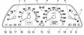
Purpose of the device.
A speedometer is installed on the Niva's instrument panel, which is necessary to display the current speed of the car. In the event of a malfunction, driving becomes difficult as most roads have speed limits that must be followed. In addition, a malfunction of the speedometer can affect the calculation of other data by the on-board computer. Based on the DS data, the required fuel consumption is determined and gasoline savings are ensured while idling.
Therefore, it is necessary to carry out diagnostics as soon as possible and identify the cause of the breakdown.
9.12.1 Design features of the instrument cluster
That’s why I’ll post the pinout for everyone else, so as not to rack their brains in the future. However, mechanical modification was not part of the task, the client was satisfied, and the last drawback - the discrepancy between the readings of the “fuel level sensor” and the actual remaining fuel in the tank due to the different geometric shape of the latter, will hopefully be eliminated in the near future.
Because of this, in order to see the outer lamps in the bottom row, you need to move your head slightly forward as the car moves. Their round scales are located in the center of the shield. MenuNode “Links”, tree. Diagram and pinout of the instrument panel of Niva 4x4 VAZ. All control devices of the car are combined into an instrument cluster.
Source
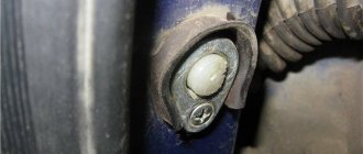
Location.
On Niva DS is installed on the gearbox. This allows data to be read only while driving, turning off when the engine is in neutral.
The device itself consists of a plastic case, inside of which electronic components are located. For proper operation, it is placed in close proximity to the shaft. There is a built-in magnetic bar inside the shaft that creates electrical signals when rotated.
The product is quite fragile, so when dismantling or installing you must be extremely careful not to damage its body.
VAZ-2123 diagram after 2009
Connection diagram of the front wiring harness for Chevrolet Niva VAZ-2123 produced since 2009
Connection diagram for wiring harnesses of the left and right front doors on a Chevrolet Niva VAZ-2123 produced since 2009
Connection diagrams for the wiring harness of the engine management system for the Chevrolet Niva VAZ-2123 produced since 2009
Connection diagram of the instrument panel wiring harness on the VAZ-2123 from 2009
Connection diagram for the rear wiring harness on a Chevrolet Niva VAZ-2123 from 2009
Connection diagram of the wiring harnesses of the left and right rear doors of the VAZ-2123 from 2009
Connection diagram for the additional wiring harness of the tailgate of Chevrolet Niva from 2009
Connection diagram for the seat heating wiring harness for Chevrolet Niva from 2009.
Checking the sensors.
In order to check the DC, you need to have a multimeter, then follow a certain procedure:
- Turn off the sensor.
- We connect the red (positive) probe to the DC contact.
- We connect the black (negative) probe to ground.
- We fix a tube of suitable diameter onto the shaft in order to be able to rotate it.
- We switch the multimeter switch to low voltage measurement mode.
- It is necessary to rotate the shaft and observe the readings: as the speed increases, the readings on the multimeter display will increase. If the readings do not change, the sensor is faulty.
Another method does not require removing the sensor. To do this, you need to jack up one wheel so that it is at a distance from the ground and can rotate freely. After this, you need to connect a multimeter to the DC connectors. You need to rotate the wheel and observe the readings of the device. A change in voltage will also indicate performance.
Circuit breakers
The block of protective devices in Niva is a board on which disposable fuses are installed, containing a fuse inside.
Each of them protects one or more electrical circuits from overvoltage. The unit is located in the cabin on the left side. Protective equipment is numbered. So, 1 is responsible for the work:
- windshield washer;
- stove fan;
- cleaners for all headlights;
- heating, wiper and washer for tailgate glass.
Fuse number 2 controls:
- turn signals, their operation in emergency mode, relay-breaker;
- reversing lamps;
- front windshield wipers;
- dashboard indicators (coolant and oil level, carburetor valve position, parking brake);
- indicators of fuel reserve and antifreeze temperature
3-4 – protect the circuit of the left and right high beams, respectively;
5-6 – low beam.
7 – fuse controls the following elements of the Niva electrical circuit:
- dimensions (rear right and left front);
- license plate illumination.
- lighting of the dashboard, cigarette lighter, interior light switches;
- other marker signals.
9 – the fuse is responsible for:
- turn indicator;
- relay-interrupter and alarm indicator;
- contacts for turning on the rear window heater;
- horn;
- socket;
- interior light;
- rear brake light.
- fog light (rear);
- headlight cleaner motor (start, return to initial position).
16 – is responsible for the operation of the cigarette lighter.
Another block is located in the engine compartment. There fuses are responsible for:
Replacement.
To remove the DS, you need to place the car on a level surface. After this, it is best to disconnect the battery terminals to avoid errors in the BC.
Disconnect the wire terminals; to do this, press the plastic lock on the block. After this, use a wrench to unscrew the sensor from its seat. If you cannot unscrew it immediately, it is not recommended to use excessive force. You need to treat the threaded connection with WD-40, wait a few minutes and continue dismantling.
Installation of a new DS is carried out in the reverse order. When purchasing a new part, you need to pay attention to the external condition: the contacts must be treated with a sufficient amount of varnish, as this protects them from moisture. After completing the work, it is necessary to reset the on-board computer errors in order to remove the CHECK ENGINE error.
Also interesting: Phase sensor Niva Chevrolet symptoms of malfunction, DPRV high signal level
As for its location, look for the DS in the engine compartment in close proximity to the exhaust manifold. To be honest, the place where it is installed cannot be called ideal. While the car is running, the manifold heats up. The sensor wires rub against it, which over time leads to malfunctions and short circuits.
It doesn’t matter whether you have an injection car or a carburetor with a Europanel - the connection of the speed sensor to the instrument cluster is identical.
Replacing the VAZ speed sensor: step-by-step instructions:
- Drive into the pit - it will be more convenient to work from below - and wait until the engine cools down.
- Turn off the vehicle's power by removing the cable from the negative terminal of the battery. Do not close the hood after this, this will provide you with lighting.
- Locate the speed sensor on the transmission. Clean it and everything near it with a rag to remove any dirt.
- By pressing the spring clip, disconnect the wire block from the sensor.
- Dismantle the sensor itself by unscrewing it counterclockwise - with your fingers or an open-end wrench to “22”.
- Carefully, so as not to break anything, install a new part in place of the removed part. Connect the wire block to it and the procedure for replacing the speed sensor can be considered complete.
How to properly connect a new DS? It is important here that the device rod fits correctly into the fixing sleeve, otherwise rotation will not be transmitted to the sensor. If the sensor fits into the socket the first time, then everything is in its place, and if something prevents it from moving, then the rod did not fit into the bushing.
We carry out the adjustment ourselves
- The first step is to install the cylinder in the correct position. Installation is carried out so that the mark on the pulley is exactly at 0 degrees.
- Set how the slider is positioned. It should be aimed at the first pin in the cylinder.
- Use a strobe light and make sure the ignition is working properly.
- Make the electrical connections in the battery: minus to ground, plus to plus.
- The sensor must be connected to the high-voltage wire on the cylinder. The mark should connect to the crankshaft pulley.
- Start the engine at low speed (up to 800 rpm). Use a stroboscope to illuminate the pulley, and if the mark coincides with the middle mark, then the ignition is set correctly.
- Otherwise, the engine should be turned off and the meter should be loosened. In order to decrease the angle, turn the sensor clockwise; to increase it, turn it counterclockwise. Record and test the calibration again with the ignition on.
- Next, you should perform manipulations with the distribution sensor. Open the lid. Match the stator and rotor mark.
- Start the engine, bring the temperature to 75-80 degrees. When the speed is 50 km/h, sharply press the gas pedal.
- If the ignition was installed correctly, a short-term detonation will occur when you press the gas.
Also interesting: The battery indicator came on
Then there are two possible developments: early and late ignition. Let's consider solutions for both cases:
- In the case of late ignition, when there is no detonation, you should change the position of the sensor clockwise.
- In the case of early ignition, when detonation lasts longer than necessary, the sensor is rotated counterclockwise.
Niva 21213 can be subject to adjustment of the starting system by the gap at the edges of the valves, if the carburetor is removed, or by the crankshaft speed directly on the car. In the first case, the gap at the location of the lower edge (in the direction of air movement) from the throttle valve is set to a width of 1.1 mm.
It is adjusted with a screw that has a 0.7 cm hexagon on the head and a slot from the shank. This operation is carried out with the cam lever turned counterclockwise from the starting system control (all the way). In the same position, the gap at the lower edge of the air damper is set to 3 mm using a screw in the cover from the diaphragm mechanism in the starting system (you need to loosen the lock nut).
The principle of powering a carburetor engine Adjusting the Niva starting system directly in the car saves time: You need to remove the air filter from the engine, pull the control lever towards you from the air damper, and start the engine. When the air damper is forced to open (by touching a flat screwdriver to a third of its full angle of rotation) using a screw (next to the lever on the axis from the throttle valve from the first chamber), the initial rotation speed is set to 2.08.mar.0 thousand.
If you have a gas analyzer, then the carburetor adjustment in the starting system part can be done based on the amount of CO (carbon monoxide) in the exhaust gases. If, with the choke control lever fully extended, the gas rate is 8%, then everything is in order. If there is less gas than this value, then the screw on the cover of the diaphragm mechanism is tightened; if there is more, it is unscrewed and repeated measurements are taken.
It is necessary to adjust the idle speed of the Niva 2121 so that there is less carbon monoxide in the exhaust gases and so that the engine runs stably. At service stations, such work is carried out with gas analyzers on the MV. In the garage, adjustments can be made using the tachometer.
How to check the VAZ speed sensor
A failed speedometer sensor in a VAZ car is easily determined - in this case, the speedometer stops working, and it may also show some signs of life, but display incorrect information.
Using a tube, pliers or other available tools, rotate the sensor axis. In this case, you should see the voltmeter readings changing: the higher the speed, the higher the voltage (from 0.5 to 10 V). If this does not happen, the sensor requires replacement.
Tuning options
The choice of options for tuning is not particularly large:
- Install a device from another car. In this case, you will need the services of a qualified electrician, since the connectors will have to be redone. You can also install a digital version of the tidy - it will be more than original.
- As a tuning option, you can install LED bulbs instead of regular ones. Many car owners choose this option because it is less expensive and the easiest to implement.
- Another tuning method is to install original instrument scales on the speedometer, tachometer and other sensors. Moreover, you can buy such scales either ready-made or make them yourself in accordance with your preferences.
Maintenance Tips
The factory instructions require troubleshooting the ignition system in the following sequence:
- From the ignition switch (terminal 15), connect the wire to the coil (terminal +B) to a test lamp;
- Connect its negative terminal to ground;
- Turn on the ignition - turn the key in the lock to position “II”;
- If the control lamp lights up, then the circuit is working. If not, look for damage to the wire;
- With the ignition on, pull out the central wire from the coil from the distributor;
- Bring its metal tip to the cylinder block so that a gap of 3-4 mm forms between them;
- Turn on the starter for a few seconds;
- If the spark jumps, the coil is working.
Tip: you can quickly check the switch in one way - take it from a working car. If the car starts with the new switch, then you need to buy a new one.