Probably, hardly anyone will argue with the fact that the VAZ “ten” is not the pinnacle of design thought. However, there is nothing surprising here, because this car was designed back in the last century. At the same time, the compensator, and quite a serious one, in this case is the price. In other words, a certain compromise is proposed - the imperfection of the car in exchange for an acceptable cost. Well, the choice is ultimately made by the car owner himself, deciding whether this option is suitable for him.
You can talk about the advantages and disadvantages of this model for quite a long time. However, this is not what we are talking about now. Those who decide that the “ten” is a suitable option in terms of the ratio between price and quality often want to somewhat refine their iron horse during operation, making changes to both the exterior and the interior.
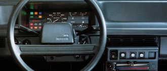
If we talk about tuning the car interior, then one of the main objects of improvement here is the dashboard. Many people simply don’t like the native version, which, frankly, doesn’t look very attractive. Yes, after the “Zhiguli” this is an undoubted step forward, but it’s already the 21st century outside the window, and I want something more beautiful and pleasing to the eye.
Which wires go where on the VAZ 2110 instrument panel pinout
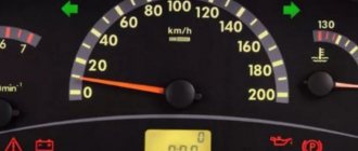
Let's be honest - the VAZ 2110 does not have the most beautiful “native” instrument panel, neither on the first cars nor on the “improved” ones.
Therefore, many owners of this model are trying to make it more modern and somehow decorate it (with LEDs, beautiful lights, etc.). But, before you decide on some kind of upgrade, it is necessary that you have before your eyes the pinout of the instrument panel for the VAZ 2110, otherwise you can simply get lost in a heap of wires, sensors and buttons. Moreover, it will be useful regardless of whether you completely change the panel, or simply make some additions to the dashboard of your VAZ 2110.
Malfunctions and repairs
Instruments or indicators may fail. This could be part of the indicators or even the entire speedometer. VAZ 2110 owners rarely encounter this situation, since the dashboard works properly, especially in domestic cars. Before changing the instrument panel or repairing individual parts, you should make sure that the sensors are working properly - we use the on-board computer.
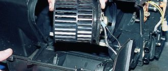
Inaccurate installation leads to failure of elements. On the instrument panel board, the parts are attached using simple rivets, hence the negative result. The body is constantly subject to vibrations, so the installation simply “falls apart” and breaks appear in the circuit. Repair in this case involves soldering the rivets and thoroughly cleaning the contacts.
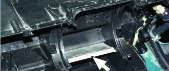
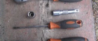
- It is necessary to remove the plug; the board does not need to be disconnected from the case.
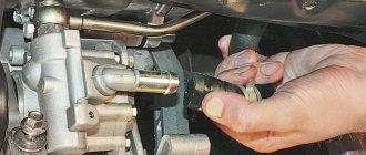
- The next step is to apply flux to the places on the board with arrows (photo below). Both pads also need to be removed and thoroughly lubricated.
After soldering is completed, the instrument panel can be returned to its place. If you have free time, you can go through the contacts using sandpaper. On older cars they usually oxidize, which can prevent the devices from functioning properly.
You can see how to remove the dashboard in the video below.
Connection knowledge
Before starting dismantling work, you need at least a conventional pinout on paper, otherwise it will be very difficult: you will need to “trace” every wire and every connection that is on the “path” from the devices to the power button.
In fact, the pinout of the VAZ 2110 dashboard is not so difficult to understand, but there are differences between cars produced in different years and at different factories. There is an old model, there is one with a mechanical odometer, and a new (Euro) model, so there are differences in the pinout of the instrument panel, depending on the type to which it belongs.
Alexmtx › Blog › Correct connection diagrams for electric windows (ESP) and glass closers
When you need to install ESP (electric windows) yourself, then, as always, on the Internet it is difficult to find correct and understandable diagrams for everyone. Having experience in radio electronics, I am laying out for everyone the correct and understandable diagrams for connecting an ESP, an intelligent glass closer Pandora DWM-210 (but it is better to install a Sheriff PWM-200), as well as simple closers only for raising the glass, installed in the wire gap on the positive side of the motor.
We take ESP power keys (not trigger (multiplex) from Itelm): a block from Granta, and a new model button from Kalina (it is the power key), since they are the cutest in appearance.
These are, of course, not dual-mode imported buttons, but they will work just as well with an intelligent door closer. We also install the Sheriff PWM-200 type door closer itself. We use thick power wires (shown in bold in the diagrams) >= 1 mm2, while control wires can be used thin = 0.5 mm2.
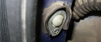
Power buttons are easy to identify by their contacts - they have thick and flat blades, while trigger buttons have thin pins like needles! Exception! If the buttons are not on the door, but on the center console and thick wires >= 1.5 mm2 are stretched from them to each door, then you can do without a relay, since there is no duplicate button here, and each one has its own door and the drawdowns are minimal. Then you don't have to read further.
Plus +12V must be taken from the fuse block, and not from the ignition, otherwise the automatic window closer will not work when arming. It is better to take the weight from the bolt behind the mounting block, and not in the door, since the contact in the door may not be very good. Although the door contact is also good if the car is not old. Take tinned terminals.
Connection diagram for power window lifter button "AVAR"
Diagrams for connecting the backup button on the driver's door to the main button on the passenger door
When installing two buttons on one window regulator, they are usually installed in series (or in parallel, but then they must be decoupled via a relay).
The main button is the button that controls the power window of the door on which it is installed. The duplicate button is the driver's button, which additionally controls another window regulator from the driver's seat.
Daisy chain connection (for trigger buttons)
We connect the output of additional button 1 in the driver's door to input 6, and output 7 to input 3 of the main button on the passenger door. We cut the wires in the block connecting contacts 5-6 and 6-3. The minus of contact 5 now goes only to the backlight, and contacts 6 and 3 now take output from additional buttons 1 and 7 of the driver's door. Installation in parallel will result in short-circuiting during lifting and lowering. Power wires are highlighted in bold.
Parallel connection (only for power buttons)
Since with a serial connection you still can’t do without a relay, it is better to make a button duplication circuit in parallel, decoupling the main button from the backup button through two 5-pin relays: the wires from the main button next to the driver’s ESP motor go directly to the 88th contact of the relay and from pin 30 directly to the engine, and long wires from the backup button go to pin 85 of the relay winding, and the relay feeds a powerful plus to the passenger’s ESP engine.
A parallel connection for power buttons is preferable, since there is no need for a relay on the main (passenger) button (the wires here are short), and we thereby eliminate unnecessary clicking of the relay when the main button on the passenger door operates. For non-power (trigger) buttons, in this case, you will definitely have to use 2 more extra relays to relieve the load on the passenger button (therefore, a serial connection is always used for trigger buttons). Further, everywhere in my circuits a parallel connection is used, since all the buttons are power
.
Connection diagram for multiplex (low-current) ESP button
ESP connection diagram when the multiplex button closes the contacts to ground
Dimensions of the installation location for the ESP “AVAR” buttons
Glass closer Pandora DWM-210
What it gives: - full glass travel in one short press (“one touch”) - BUT DOES NOT WORK ON 2 GLASSES AT THE SAME TIME (since the module has only one sensor for electromagnetic noise of the motor, current and time); — stopping the glass in any position by pressing again in any direction; — automatic stop of the glass when it encounters an obstacle in the window opening; — automatic shutdown of ESP motors when current is exceeded; — automatic closing of windows when arming the car; — automatic opening of the windows when disarming to the previous position before arming, if the parking lasted no more than 20 minutes. (The rev counter works rather conditionally and may leave the windows closed or not closed enough). The closer is installed in the driver's door.
ATTENTION! When you hold the button, the closer does not use its relays
, which take the plus (through a 20A fuse) and minus from the closer, but sends all the current directly from the button to the motor, so you need to install a relay after leaving the button with long wires!
Apparently this was done so that if the door closer fails, you can always close the window by simply holding the button. When you briefly press
the button, the door closer with its relays is activated and closes the glass.
Place the relay only at the input to the closer from the output after the duplicate button!
If this is not done, then due to subsidence along the long wires of the sequential connection of the buttons, the passenger window will barely move.
The output of the closer must be connected directly to the motor without a relay, otherwise the detection of electromagnetic noise from the motor will not work and the closer will not work!
At the output of the driver's power button, relays are not needed, since all the power wires there are short.
It is ideal to install 2 door closers on each door, as is standard on foreign cars - then the AUTO mode will be on 2 doors at once in parallel, and not alternately. In addition, you will not need to pull 2 extra thick wires to the motor from the driver's door to the passenger's door. If I had known right away that the Pandora DWM-210 is such a Ketai crap without its own relays in the power part of the closer, I would have purchased and installed a Sheriff PWM-200
, in which the power part is clearly separated from the control part and, moreover, you can close two windows at the same time in one touch! So it's definitely better!
This is interesting: What to do if the “CHECK” lights up?
The power windows are turned on by the module sequentially after a trigger pulse is given: first the driver's door, then the passenger door, and the next channel is turned on after the previous one has been completed. If the glass is already closed, the module will immediately switch to the next channel. Closing control is carried out by electromagnetic noise from the motor.
When the power is turned on, the closer module needs to be calibrated based on the protection current. You need to press SHORTLY to lower each glass all the way, then raise it in the same way. At the same time, the closer remembers the characteristics of the engine. The control signal for closing and opening is NEGATIVE ONLY. Control can be done from the central locking or from an additional alarm channel. It is necessary to connect the control output of the security system to the “White/Red” (windows up) and “White” (windows down) terminals of the module, respectively. The duration of the trigger pulse must be at least 500ms. (0.5 sec.). Attention: in older releases the wires of the buttons and motors were swapped - for such blocks we swap the wires under the numbers: 9 2, 16 20, 15 10, 14 19, 13 18. On the latest Pandora (November 2011 and newer) the diagram is correct, so that there is no need to swap wires from buttons and motors!
Closer in wire break for lifting ESP
Addition dated 10/05/2014 at the request of SIBUR95. There are closers that are connected to the break in the lifting wire that goes to the ESP motor. There are 2 wires coming from the closer and they are constantly closed in it. When you turn on the closer, they break and + appears on one, and nothing on the second. On GREEN, when the door closer is operating (arming), a plus appears and it goes to the engine, and a minus goes from the button (or from the relay from contact 88 to 30) to the engine. When the closer does not work, it simply passes current from BLUE to GREEN by closing its relay and that’s it.
Here the circuit differs only in that the minus of the motor is connected directly to the button (or to the relay, if the button is duplicated), and the plus also passes through the closer, and the relay is located at only one input to the closer, thereby not interfering with the detection of engine noise.
You can also make a button duplication circuit not in series, but in parallel on two 5-pin relays. The advantage is that a series circuit is eliminated; the relay will not click again from the main button, which is closer to the engine (with short wires), but only from the backup one. The downside is that for non-power (trigger) buttons in this case you will have to use 2 extra relays (relays 3 and 4 in the diagram).
Scheme for any number of duplicate buttons and number of doors
You can put as many buttons in parallel as you like and simultaneously press them in different directions - a short circuit is impossible from the circuit design! In a situation where we press the up button on the main button, and the down button on the backup button, it will simply stop, since both power lines will have the same potential.
The only difference between the closer is the presence of an MK between the buttons and power relays. The advantage of the circuit is that the power switching is in one place, there are no losses in the harnesses and on the buttons, there is a minimum of “pulling” of wires - 2 in total per channel + ground. In good quality, full-featured closers, the power part and control lines are implemented in the same way + the functions of “auto-detection” of active control levels are also added.
If a door closer of the PWM-200 on Sheriff type with low-current control is installed, then there is no point in these relays, since they are already mounted in the door closer. This circuit with a relay is for understanding the essence of reverse control and duplicating buttons in parallel. Power outputs both in the central locking system and in the door closers are implemented in exactly this way.
It is also advisable to connect non-polar electrolytic capacitors of 22 uF 25V to the contacts of the ESP motors in order to smooth out the range of current ripples in the power channel of the closer so that it works correctly even when the motors are worn out and does not suddenly stop the glass when opening and closing.
The usual scheme of duplicate buttons for 4 doors
Duplicate buttons must also be supplemented with two 5-pin relays (they are not shown in the diagram).
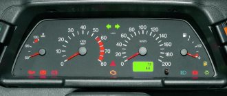
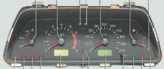
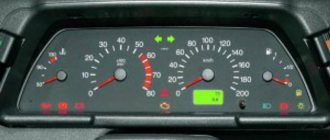
General diagram of devices
If you look from the back of the instrument panel, here it is in sequence - from top to left to right:
- Fuel level indicator;
- Combination of instrument lighting lamps;
- Right turn control;
- Left turn control;
- Tachometer;
- Next is the block, there are a lot of plugs in it;
- And the top part of the dashboard is completed by an antifreeze temperature indicator.
VAZ 2110 dashboard connection diagram
The lower part of the dashboard (also from left to right and from the back of the dashboard). The following part of the instruments is located here:
- high beam controller (bulb);
- alarm controller;
- brake fluid level control lamp;
- speedometer;
- CHECK ENGINE controller;
- battery charge control;
- parking brake controller;
- oil pressure controller;
- air damper controller in the carburetor;
- outdoor lighting controller.
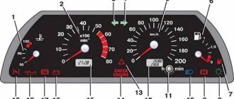
White block
The connector number, wire color and the unit (assembly) to which it goes are located in the white block as follows:
- The first connector has a black wire. Its purpose is the body (mass);
- In the second - red-brown - this is a low-voltage supply from the electronic control unit - tachometer;
- The third, yellow one is also a tachometer, but this is a high-voltage supply from a coil;
- The fourth, red-blue is Const from the battery + 12V, going through the sixth fuse;
- The fifth, green-white - it is intended to indicate the coolant temperature;
- Sixth, green-yellow – for size fuse F1;
- The seventh connector does not have its own color and goes to the “choke”, the throttle valve;
- Eighth, red and white - CHECK ENGINE light;
- In the ninth and tenth there are 2 orange wires each, leading to 2 power fuses F19+12V;
- In the eleventh there are 2 blue-brown wires leading to the “BK” terminal of the parking brake;
- The twelfth, brown-white is the output “D” of the generator;
- Thirteenth, gray and blue – for the oil pressure sensor.
White block (X1) and Red block (X2) of the VAZ 2110 instrument panel
Red block
The number is the connector according to the account, followed by the color of the wire and an indication of the device to which it goes in the red block of the VAZ 2110:
- Blue and red go to the sensor showing the external temperature;
- Orange - power fuse F19+12V;
- Black, 2 wires – ground, body;
- White - light switch for all devices;
- Blue - right direction indicator;
- Blue and black - left turn signal;
- Blue with pink - TJ level;
- Brown – leading to the trip computer;
- Gray - speed indicator;
- Pink - Fuel gauge (terminal “T”);
- 2 black-green wires - high beam fuse (F3);
- Blue and white - emergency light switch;
- White - leading to the ignition switch (terminal 50).
FakeHeader
Comments 118
What could it be, I connected it according to the diagram, without a temperature and fuel consumption sensor, and the starter stopped turning? before this, after not touching the wires everything was fine
It’s strange, of course, because the shield in this case is not connected at all with starting the starter. The new ones have immo, there is only an indication. Does the shield itself work “adequately”?
So I think it's strange. The native immo works. The shield works, except for the gasoline needle, but I think that's the problem. Could there be something wrong with the wires not being connected? but also strange
By the way, have you checked the starter circuits directly? Starting with the lock, relay, etc. Does the circuit at least close when turning the key?
Yes, I looked. I changed the relays and visually the wires. Got it. It was necessary to connect together the cut wires of pin 9 of the white block. Oddly enough, the car started. Now it torments me why the tidy resets to zero every time...
It’s clear, it even became interesting - I need to look at the old car diagram to see where the 9th one goes. I usually don’t do this if I have to completely remove the connectors (pads). First, I connect what is necessary for the new option, then, according to the diagram, everything unnecessary (unused) is removed from the harness, and then the remaining but still used wires are connected) Most often, looped masses and power wires, lighting (from the dimensions), and less often signal wires remain. Is it reset, in the sense that all the icons light up, the so-called test mode? Or LCD screen readings?
Everyone does it in their own way, but they still come to the truth. The icons light up when the ignition is turned on, the readings on the screen are updated every time, right? And I noticed that the arrows can hang in one place, and then when I turn the key again, they return. It seems like I’m looking at the diagram, and I didn’t connect pin 20 of the new one correctly, to pin 13 of the red one, but it should have been to pin 4 of the white one...
That's why I asked what exactly was happening. I just wanted to know what happened with the food. Very often they confuse plug-in 12V and constant 12V, which also came to light after the conversation. 20 contact terminal 30 (permanent) 21 contact terminal 15 (after ignition)
Now I have changed it. Everything has become normal. Does not reset. All that remains is to set the arrows
This is good! Set to zero position? The movement of the hands can be checked by turning on the test mode of the shield, it is more convenient.
When I set them to 0, I connected them, and they fell. Then I took it apart again, turned it against the direction of travel, everything works) I’m happy