– one of the most common devices used to automate processes in electrical engineering. In fact, it is an automatic switch that connects or disconnects electrical circuits when the set values are reached or under external influence. Relays are used in industry to automate technological processes, in household appliances that are found in every home, such as refrigerators and washing machines, to protect the network from too high or too low current parameters. Selecting the right device simplifies the classification of relays according to various criteria.
General description of the design
The concept of “relay” unites a whole family of devices of different designs. But in general, a relay consists of three main functional elements:
- Perceiver.
This is the primary element that perceives the controlled quantity and converts it into another physical quantity. - Intermediate.
Compares the received value with the specified parameter. If this value is higher or lower than the specified parameter, then the primary effect is transmitted to the actuator. - Executive.
This element transmits the action to circuits controlled by relays. As a result of such an impact, the following may occur: opening or connecting the controlled circuit, switching current parameters.
The design and operating principle of the primary element depend on what purpose the relay has and what physical quantity (current, voltage, light, heat, etc.) it is set to.
Main characteristics of the relay
Regardless of the type and principle of operation of the relay, there are several parameters that you pay attention to when choosing this device:
- Response time is the time interval between the arrival of the control signal and the effect on the controlled circuits.
- Switched power is the permissible power of the electrical circuit or electrical installation that the relay will control.
- The setpoint is usually an adjustable parameter that determines the value of the incoming parameter (current, voltage, frequency, pressure, temperature) at which the relay operates.
What is the engine blocking alarm used for and how does it work?
The ability to reliably block the engine from starting in the event of an alarm is necessary for the alarm system. Another thing is that it is not so easy to block the engine correctly: by modern standards, it is considered necessary for the car thief to spend at least half an hour bypassing the protective circuits. Therefore, it is not without reason that it is said that an alarm installer must think like a thief: when installing an alarm, the first question he asks himself is “how can it be turned off or bypassed?”
Types of relays: contact and non-contact
According to the design of the executive component, relays are divided into contact and non-contact.
Contact
They influence the controlled circuit using electrical contacts. Opening or closing them completely disconnects or closes the electrical circuit. The following materials are used to make contacts: copper, silver, tungsten. Number of contacts – up to 10 pieces. Four- and five-pin relays are used in automobile electrical circuits to switch and switch circuits.
Contactless
Such relays act on the controlled circuit by changing the electrical parameters of the output electrical circuits - capacitance, resistance, inductance, current or voltage.
2nd connection option (restoring the operation of the seat belt warning device)
I traveled like this for a week and realized that I was somehow uncomfortable and missing something. It turned out that the same light went out on the panel and the squeak of the belt buzzer disappeared. And I decided to restore it. You will need a 4-pin automotive relay (5-pin is also suitable), the diagram is as follows:
Terminals 30 and 87 of the lower relay go to the belt warning chip on the ECU side. Looks like that.
Now the recorder turns on and off, and the seat belt warning light works normally.
Classification of relays by switching method
Primary
These devices are connected directly to the circuit of the element they are intended to protect. Their advantages are that instrument transformers, operating current sources, and control cables are not required.
Secondary
Connected to a circuit using secondary transformers. This is the most common type of relay. Their advantages are insulation from high voltage, the ability to locate the device in a place convenient for maintenance. Secondary relays are available as standard. They are designed for a current of 5 (1) A and a voltage of 100 V and can be installed in any electrical circuit, regardless of their current and voltage.
Opening the trunk using the car alarm key fob
If your car has an electric trunk drive, you can connect to it with a car alarm to open it using the alarm key fob. If the alarm outputs a low-current signal to open the trunk (and most often this is the case), then we use this circuit.
First of all, we find the wire to the trunk drive, where +12 Volt appears when the trunk is opened. Let's cut this wire. We hook up the end of the cut wire that goes to the drive to pin 30. We hook up the other end of the wire to pin 87A. We connect the alarm output to contact 86. We connect contacts 87 and 85 to +12 Volts.
Types of relays by purpose
According to their purpose, these devices are of three types - control, protection, alarm.
Control relay
These relays are primary. Mounted directly into the electrical circuit. Their role is to turn on and off individual elements of the circuit. They can be used independently or as components of low-voltage complete devices - boxes, panels, cabinets.
Protection relay
Perform the functions of turning on, turning off and protecting devices with thermal contacts - electric motors, fans. When the temperature is exceeded, the thermal contacts open. The equipment can resume operation only after the thermal contacts have cooled to the set temperature.
Alarms
Such relays are installed in security systems of vehicles, enterprises, and local areas. They are used to generate a signal when a set value of a parameter that is under control is reached (current, voltage, frequency, pressure, temperature, acoustic parameters and others).
Types of electromechanical relays
The most common type of electrical relay is electromechanical. These include: electromagnetic, induction, electrothermal devices.
Electromagnetic
One type of electrical relay is electromagnetic. The design of this device includes: a winding with a steel core, a group of movable contacts that make and break a controlled electrical circuit. Let's consider the principle of their operation:
- A control current is supplied to the core coil.
- A magnetic field is created in the core under the influence of electric current, attracting the contact group.
- Depending on the type of relay, the contacts close or open the electrical circuit.
A variety of electromagnetic relays are polarized, which differ from neutral ones in their ability to respond to the polarity of the control signal. The opening or closing of the contacts depends on the polarity of the electromagnet connection. They have higher sensitivity compared to neutral relays. Such devices can only be used in DC circuits.
Electrothermal (thermal)
Thermal relays are a complex of bimetallic plates, for the manufacture of which metals with different expansion coefficients when heated are used. Such relays can be used as protective devices: when the temperature set by the regulator is exceeded, the contacts are disconnected and the flow of current to the consumer is stopped.
Typically, thermal relays are used in household single- and three-phase networks when connecting electric motors. When the load on the engine increases above a set value, the bimetallic relay heats up, which, when a certain temperature is reached, opens the electrical circuit. The engine stops running. After the bimetallic plates cool, the circuit closes and the engine resumes operation. Thermal devices can be equipped with a wheel that adjusts the engine shutdown temperature and a forced start button.
There is a type of thermal relay in which bimetallic plates are replaced with a low-melting alloy. They operate almost instantly - when a certain temperature is reached, the metal melts and the circuit opens. The principle of operation of such devices is similar to the principle of operation of fuses. After operation, such a relay, installed directly on the equipment as a last resort against burnout, must be replaced.
Induction
The operating principle of these devices is based on the interaction between alternating magnetic fluxes and currents that form alternating magnetic fluxes. Induction devices are designed for use in alternating current circuits only. There are three types of induction relays - with a frame, a disk, and a cylindrical rotor (“glass”). These devices are widely in demand in relay protection and automation systems.
Solid state bodies – should we use them?
To begin with, we will also consider the feasibility of using such relays. For example, a real case:
The simplest temperature controller, the accuracy of maintenance is not essential. Load – heating elements, work in water around the clock. More often than once a year, one of the heating elements shorts or shorts to the housing. There is a high probability that the TSR will burn out, since they are very sensitive to overloads.
Overloads and protection of solid-state relays will be discussed in detail below, but in this case it is advisable to use a conventional contactor, which copes well with overloads and costs 10 times less.
Therefore, it is not worth chasing fashion, but it is better to use sober calculation. Calculation by current and finance.
If it occurs to someone, you can use a bell button or a reed switch to start a 10 kW engine! But it’s not that simple, the details will be below.
Expert opinion
It-Technology, Electrical power and electronics specialist
Ask questions to the “Specialist for modernization of energy generation systems”
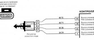
How does a relay work in a car? 4 contacts of a fuel pump, if the control input 30 is from the ignition switch or battery through a fuse, output 87 to the fuel pump 86 ground body 85 control from the UPD 03 ECU. Ask, I’m in touch!
Other types of electrical relays
Solid State
These electronic devices are compact and durable due to the absence of rubbing mechanical parts. The mechanical work here is performed by semiconductor elements - bipolar and MOS transistors, thyristors, triacs. Compared to solid-state ones, they have the following advantages:
- Low noise level during operation.
- Very high mean time between failures, which is 100 times or more greater than the service life of electromagnetic devices.
- The response speed is a fraction of a millisecond; for electromagnetic ones it is 50 ms - 1 s.
- Power consumption is 95% lower.
However, solid-state relays have not only advantages, but also disadvantages. One of them is poor resistance to surge voltages, which are practically not dangerous for electromagnetic relays. When using solid-state relays, it is necessary to provide a circuit design that limits these pulses. There are also disadvantages - heating during operation, the presence of leakage currents, leading to the presence of voltage on the phase wire even when the relay is turned off.
Solid-state relays are used in temperature control systems, in which heating elements are used as heaters, in industrial automation, telemetry, equipment mechanisms used in the metallurgical and chemical industries, in medical equipment, and military electronics.
Reed switches
This type of relay is a reed coil. This is a cylinder filled with an inert gas, or inside of which a vacuum has been created. Inside the cylinder there are connecting elements made of permalloy - a precision alloy (an alloy with a precisely specified chemical composition), including iron and nickel. These connecting elements are in the form of wire with contacts. They are coated with silver or gold plating. The reed switch is placed in the middle of an electric magnet or within the range of its field. When current is applied to the winding of an electromagnet, a magnetic flux is formed, which locks the contacts. Reed relays can perform the following functions: making, switching, breaking. The advantages of these devices are compact dimensions, affordable price, and the absence of rubbing parts, which extends their service life. The fact that the contact group is located in an inert gas or vacuum and is reliably protected from moisture increases the reliability of the relay.
When using reed relays the following should be avoided:
- the close presence of an ultrasound source, which will negatively affect performance;
- exposure to foreign magnetic fields;
- mechanical damage.
The flask is usually made of glass, so it must be protected in every possible way from mechanical influences. If the bulb is broken, the contact group will not operate. Reed relays can only be used in systems in which the power supply parameters are within the limits established in the technical documentation. If too high a current is applied, the contacts will open. Malfunctions in the operation of reed relays are also observed in cases where current is supplied at too low a frequency.
Photoelectronic (photo relay)
The basis of a photoelectronic relay is a semiconductor element - a photoresistor, the resistance of which varies depending on changes in illumination. Photo relay is a device widely used by public utilities. It is reliable in operation and provides significant energy savings and safety on the streets. When the illumination increases, all lighting equipment turns off, and when darkness falls, it turns on. Most of these devices are equipped with a threshold regulator and a mechanical switch.
General requirements
The Starline alarm system is equipped with parameters that provide safe, comfortable conditions of use at an affordable price. Reliable operation of the Starline A91 alarm must be linked to the general requirements for its use, which are set out in the operating manual. The main ones include:
- Cars must be parked taking into account the range of the key fob;
- The vehicle's transmission must be considered;
- Safety measures are indicated when enabling autorun.
The instruction manual outlines the sequence of installation, configuration, and use of the security device (you can download the manual below).
A rich set of options makes Starline car alarms in demand in Russia and neighboring countries. The technical characteristics presented below make it convenient to use the Starline A91 alarm system.
- Car alarm radio signals are transmitted with frequencies 433.05 – 434.79 MHz;
- Designed for 128 control channels;
- The Starline A91 alarm key fob is triggered from distances in the following modes: transmission – 800 m; pager – 2,000 m; in case of using the remote control without feedback – 15 m;
- The Starline A91 car alarm operates at temperatures of -40 0 – +85 0 C;
- The maximum current value is – 200 mA – 25 A;
- The Starline alarm operates at a voltage from 9 to 18 V;
- Control panels are activated from power sources: 1.5 V – for a remote control with feedback; 3 V – with absence.
Types of relays by type of incoming parameter
According to this parameter, relays are divided into: current, power, frequency, voltage, pressure, acoustic values, amount of gas. Devices can be maximum and minimum. Relays that operate when a given value is exceeded are called “maximum”, and when it falls below a given level, they are called “minimum”.
Current relay
Current relays react to sudden changes in current and, if necessary, turn off an individual load or the entire power supply system. The maximum current value at which it is necessary to disconnect consumers is set by the regulator.
Voltage relay
Voltage relays react to voltage levels and are switched on via voltage transformers. Used to control voltage phases in electrical networks and protect electrical appliances. The basis of such a relay is a quick response controller that monitors voltage deviations outside the established limits. The generally accepted standard for operation of such relays is below 170 V and above 250 V.
Frequency relay
They are used to control the frequency of alternating current, which should be equal to 50 or 60 Hz in single- and three-phase networks. Usually have fixed response delays. The opening thresholds of the controlled circuit can be adjusted. The operating mode of this device may include the presence of a “memory” of an accident.
Power relay
The power limiting device operates similarly to a load current limiter. If the set power threshold is exceeded, the consumer is switched off. Power limiting relays are often equipped with an automatic reset function. That is, after the load is reduced, the operation of the equipment resumes automatically.
Pressure switch
A pressure switch is an important device used in pumping equipment to control pressure differences in water, oil, oil, and air. There are two main types of such devices – electromechanical and electronic.
Electromechanical relays have a special element in their design that responds to changes in pressure in the system - a flexible membrane that bends under the pressure of liquid (air) in the system. It is connected to two springs, one of which is adjusted to the minimum permissible pressure, and the second to the difference between the upper and lower limits of pressure in the system. When the pressure in the system drops below the minimum threshold, the relay turns on the pumping equipment, and when the upper threshold is exceeded, it turns off. These are simple and reliable devices, but not very easy to use. The operator has to regularly check the settings and adjust them if necessary.
Electronic devices have a more complex design. Limits can be set very precisely and are not required to be monitored during operation. Electronic devices are sensitive to water hammer, so they are equipped with small hydraulic tanks (volume - approximately 400 ml). An electronic pressure switch is installed between the pumping equipment and the first water collection point.
Acoustic relays
Acoustic relays respond to changes in acoustic quantities - the frequency of the sound wave, its pressure or the acoustic characteristics of materials - absorption and reflection coefficients. The operating principle can be mechanical or electrical. Mechanical acoustic devices have a membrane that bends under the pressure of sound waves, and when a certain pressure value is reached, the contact closes. Electrical acoustic devices include: a receiving organ (microphone, filter), an amplifier, and an output electrical relay.
Devices that respond to any noise are often used in conjunction with a lighting system. They react to any noise in the room and give a signal to turn on the light. They are usually installed in corridors and staircases. Acoustic relays are also widely used in security systems and “smart” toys.
Gas relays
These devices are used to provide gas protection. They are a metal body embedded in the oil line. The relay is normally filled with oil and its contacts are open. As the gas content increases, they fill the upper part of the relay, simultaneously displacing the oil. The float included in the design lowers as the oil level decreases, rotates around its axis and causes the contacts in the signal circuit to close. The generated signal warns of high gas contamination in the environment.
Legislation
Before practicing installing DRLs, I would like to dwell a little on the legal standards for installing DRLs, as well as the rules of their operation.
The very first and basic rule is that unauthorized installation of additional light signals on a car is prohibited. Yes, you are right, you do not have the right to install DRLs on your car if it was not equipped with them by the manufacturer. This will be considered as making changes to the design of the vehicle. For every change to a vehicle's design, a certificate must be obtained, which in itself is neither quick nor cheap. Otherwise, traffic police officers will issue you a fine, or even take your car to the impound lot.
How so? My neighbor installed DRLs on the Oka and drives calmly! - you ask. He is simply lucky to have loyal traffic police officers who do not pay attention to his DRL - I will answer you.
Once again, unauthorized installation of additional light signals on a car is prohibited if it was not equipped with them by the manufacturer. Therefore, you make any changes to the design of the vehicle at your own peril and risk. It’s a completely different matter if your car’s equipment does not include DRLs, but the more expensive trim levels of your model do have DRLs. In this case, you have the right to install DRL without any approval from the certifying authorities.
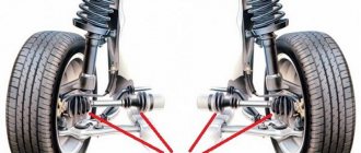
The first rule for installing DRLs concerns their location on the car body (see picture). If we briefly describe this figure, we get the following:
- DRLs should be installed at a height of 250 to 1500 mm;
- The distance between adjacent edges of the DRLs must be at least 600 mm;
- The distance from the outer side surface of the vehicle to the nearby edge of the DRL should be no more than 400 mm.
Now let’s briefly go through the rules of operation and use of DRLs:
- DRLs should only be used during daylight hours;
- It is prohibited to use DRLs in conjunction with side lights, low and high beam headlights, as well as fog lights.
Everything that is not prohibited is permitted. It's that simple
Separately, I would like to dwell on an important point, it concerns the use of DRLs in conjunction with high beam headlights. The rule sounds something like this: When the high beam signal is briefly signaled, with the side lights and low beam headlights turned off, the DRLs should not turn off
Let me break it down: you are driving with your headlights and side lights turned off, your DRLs are on, when you signal with your high beams to an oncoming car that you are approaching a traffic police post, your DRLs should not turn off.
Just? I also think that there is nothing complicated here. Knowing the legislation and rules for using DRLs, we are ready to move on to the practice of connecting them. Let's start with the simple and incorrect and end with the complex and correct. Go!
Intermediate relays
“Intermediate” is a relay that plays not a main, but an auxiliary role in the circuit.
Designed for installation in automatic circuits and control circuits. Its functions are to increase the number of contacts of the main relay, when it is necessary to close or open several circuits, close one and simultaneously open another circuit, and perform other tasks. They are used in circuits for amplifying and converting electrical signals, storing information and programming, distributing electrical energy with controlling the operation of individual elements, and interfacing elements of electronic equipment with different principles of operation. Often, intermediate functions are performed by electromagnetic relays, which, depending on the design and area of application, have the following types of contacts:
- Normally open (closing). In the absence of power supply they are in an open state. When voltage is applied, they close.
- Normally closed (opening). In the normal state, such contacts are in a closed state, and when power is supplied, the contacts open.
- Reversible. In such relays, in the absence of voltage, there is a middle contact closed with one of the fixed contacts. When current is applied, the middle contact breaks the connection with the first fixed contact and closes with the second fixed contact.
1st connection option (only the most necessary)
The diagram is like this (for those who don’t really understand what a relay is, I recommend reading this article - it’s simple and accessible. www.kolesa.ru/article/avtomobilnye-rele-kak-ustroeny-kak-ih-vybirat-i-proveryat )
SA1 is a switch in the seat belt buckle that opens the contacts when the belt tongue is snapped into place.
The VD1 diode is needed so that the relay does not go into woodpecker mode after pressing the SA2 button (manually turning on the recorder at any time). The estimated current in this circuit will be 0.3-0.4 A, based on the peak needs of the recorder 5V 1A. You can install the same 1N4007 (1A diode, it will be discussed below in the description of relay modifications), but it is better with a reserve of the 1N5401 type (3-amp diode). So, we throw off the chip under the driver’s seat and immediately get a nice bonus (depending on who, of course) - now there will be no annoying squeak of the seat belt buzzer and the seat belt light on the dashboard will not be an eyesore. The signal circuit is now open and the car believes that the driver is wearing a seat belt.
The connected relay looks like this.
Installed in place of the old relay
Everything works great.
Relay designation on the diagram
Relay designation on a circuit diagram
On electrical diagrams, a relay is designated by a rectangle, from the largest sides of which the power terminals are shown. The functional purpose of the relay is indicated in the diagram by the letters:
- KA – current;
- KV – voltage;
- KB – blocking;
- KBS – blocking against repeated switching on;
- KH – index;
- KL – intermediate;
- KQ – fixing the switch position;
- KSV – voltage circuit control;
- KSP – pressure control;
- KSH – pressure control;
- KSL – liquid level control;
- KSR – speed;
- KSQ – substance composition;
- KW – power;
- KZ – resistance.