Generator voltage regulator relay. Such a complex, at first glance, name refers to a very small component of a car or motorcycle generator, and whose failure can cause a number of problems. For example: undercharging or overcharging of the battery. This can happen for many reasons, but in most cases the culprit of the problem is a failed generator relay (as it is usually called). Let's figure out what a generator relay is, how this component is connected to the vehicle's on-board network, how to check it and, if necessary, replace it.
Basic automatic control processes
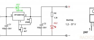
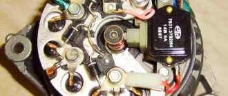
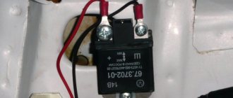
It doesn't matter what type of generator set is used in the car. In any case, it has a regulator in its design. The automatic voltage regulation system allows you to maintain a certain parameter value, regardless of the frequency at which the generator rotor rotates. The figure shows the generator voltage regulator relay, its diagram and appearance.
By analyzing the physics by which a generator set operates, it can be concluded that the output voltage increases as the rotor speed becomes higher. It can also be concluded that voltage regulation is carried out by reducing the current supplied to the rotor winding as the rotation speed increases.
Independent connection of the relay regulator to the generator’s on-board network (step-by-step instructions)
When installing a new control device, the following points must be taken into account:
- Before performing the task, it is necessary to diagnose the integrity and reliability of the contacts. This is a cable that runs from the vehicle body to the generator set housing.
- Then connect terminal B of the regulatory element to the positive contact of the generating set.
- It is not recommended to use twisted wires when making connections. They overheat and become unusable after a year of use. Soldering should be used.
- It is recommended to replace the standard conductor with a wire whose cross-section is at least 6 mm2. Especially if, instead of the factory generator, a new one is installed, which is designed to operate under current conditions above 60 A.
- The presence of an ammeter in the generator-battery circuit allows you to determine the power of power sources at a specific time.
Remote controller connection diagram
Connection diagram for remote type devices
This device is installed after the wire into which it will be connected is determined:
- In older versions of Gazelles and RAF, mechanisms 13.3702 are used. They are made in a metal or polymer case and are equipped with two contact elements and brushes. It is recommended to connect them to the negative open circuit; the outputs are usually marked. The positive contact is taken from the ignition coil. And the output of the relay is connected to the free contact on the brushes.
- VAZ cars use devices 121.3702 in a black or white case; there are also double modifications. In the latter, if one of the parts breaks down, the second regulator will remain working, but you need to switch to it. The device is installed in the open circuit of the positive circuit with terminal 15 to the contact of the B-VK coil. The conductor number 67 is connected to the brushes.
In newer versions of the VAZ, the relays are installed in the brush mechanism and connected to the ignition switch. If the car owner replaces the standard unit with an AC unit, then the connection must be made taking into account the nuances.
More details about them:
- The need to fix the unit to the vehicle body is determined by the car owner independently.
- Instead of a positive output, contact B or B+ is used here. It must be connected to the car's electrical network via an ammeter.
- Remote type devices are usually not used in such cars, and built-in regulators are already integrated into the brush mechanism. There is one cable coming from it, designated D or D+. It must connect to the ignition switch.
In cars with diesel engines, the generator unit can be equipped with output W - it is connected to the tachometer. This contact can be ignored if the unit is installed on a gasoline modification of the car.
User Nikolay Purtov spoke in detail about installing and connecting remote devices to a car.
Checking the connection
The engine must start. And the voltage level in the car’s electrical network will be controlled depending on the number of revolutions.
Perhaps, after installing and connecting a new generator device, the car owner will encounter difficulties:
- when the power unit is activated, the generator unit starts, the voltage value is measured at any speed;
- and after the ignition is turned off, the vehicle engine runs and does not turn off.
The problem can be solved by disconnecting the excitation cable, only then will the engine stop.
The engine may stall when the clutch is released and the brake pedal is pressed. The cause of the malfunction is residual magnetization, as well as constant self-excitation of the unit winding.
To avoid this problem in the future, you can add a light source to the gap in the exciting cable:
- the light will light when the generator is turned off;
- when the unit starts, the indicator goes out;
- the amount of current that passes through the light source will not be sufficient to excite the winding.
The Altevaa TV channel talked about checking the connection of the regulatory device after connecting the motorcycle to a 6-volt network.
What is a generator
Any car generator consists of several parts:
1. A rotor with an excitation winding, around which an electromagnetic field is created during operation.
2. A stator with three windings connected in a star configuration (alternating voltage is removed from them in the range from 12 to 30 Volts).
3. In addition, the design contains a three-phase rectifier consisting of six semiconductor diodes. It is worth noting that the VAZ 2107 generator voltage relay-regulator (injector or carburetor in the injection system) is the same.
But the generator will not be able to operate without a voltage regulation device. The reason for this is the voltage change over a very wide range. Therefore, it is necessary to use an automatic control system. It consists of a comparison device, control, executive, master and special sensor. The main element is the regulatory body. It can be either electrical or mechanical.
How to check a combined type regulator
The operation of the relay regulator can be established using a simple test circuit, which consists of the following parts:
- DC source with a voltage of 12 V (you must use a device with the ability to adjust the voltage value, as well as with a built-in voltmeter).
- 12 V incandescent light bulbs (use a low-power light source of 3 - 4 W).
- Wires with crocodile fastenings.
Checking the relay regulator is carried out as follows:
- Connect the power source to the relay-regulator, observing the polarity.
- Connect the wires from the light bulb using “crocodiles” with graphite brushes.
- Set the voltage on the electrical device to 12.7 V. The light should be on.
- Increase the voltage to 14.5 V. The light should go out.
If the lighting element does not go out when the voltage reaches 14.5 V, then the regulator is faulty. In some vehicle models, the automatic device may be programmed to turn off when the voltage reaches 14.0 volts. This feature of the device is normal.
If the light bulb does not light up at normal voltage levels or goes out before the electrical device produces a voltage of 14.0 V, then the relay regulator will also need to be replaced.
If there is no source of electricity in the form of a regulated power supply, then you can use a battery and a step-up transformer with regulation.
Checking the voltage regulator of the VAZ 2107 generator
Checking the voltage regulator of the VAZ 2107 generator can be done according to the scheme described above. The principle of cutting off the electric current when a certain voltage level is reached also remains the same. The difference may only lie in the features of connecting the charging relay to the current source and the control lamp. Depending on the year of manufacture of the car, various types of devices may be installed on it. On machines produced before 1996, an old-style relay-regulator was located. Such a device is also diagnosed by connecting the operating voltage to the main terminals and a test light to the brushes. New cars use integral type products (chocolate). Such a device is connected in a similar way. The contacts that go to the generator brushes must be connected to the light bulb, and the other pair to the current source.
How to check a chocolate bar on a KAMAZ generator
The principle of operation of the Kamaz vehicle relay regulator is the same as on other vehicles. When a certain voltage value is exceeded, the regulation device cuts off the power supply to the battery terminals. You can qualitatively check the part using a variable voltage source and a test lamp. A special feature of testing the device is the use of a current source with an adjustable voltage from 20 to 30 volts; accordingly, the light bulb must be of the appropriate type (24 V). It is not recommended to use a high-power lighting element. It is enough to use an incandescent lamp installed in the turn signals.
The work of checking the “chocolate” of the Kamaz generator is carried out as follows:
- Remove the integral voltage regulator from the generator.
- Find 2 contacts of the product that connect to the brushes and connect an electric light bulb to them (the polarity does not matter; it is also recommended to use wires with crocodile clips).
- The “negative” wire of the power supply is connected to the “ground” of the chocolate bar.
- The “plus” of the power supply is connected to the second output of the regulator.
The principle of testing is similar to performing work on 12-volt devices. When a certain voltage level (about 27 volts) is reached, the charging current should be switched off. If this does not happen, the device should be replaced. If the control light does not light up, the chocolate bar should be discarded.
When performing diagnostics using an incandescent lamp, it is necessary to ensure that the electric light source is in good working order, otherwise incorrect results will be obtained from checking the relay regulator of a Kamaz vehicle.
How to check the integral on a generator
To test the integral on a passenger car generator, you can use a battery and an adjustable voltage transformer. You will also need to prepare a multimeter and an incandescent lamp for turn signals. The connection diagram for the generator integral will be as follows:
- An adjustable voltage transformer is connected to the battery.
- The integral is connected to the transformer.
- Wires from the light bulb are connected to the terminals of the integral.
- To monitor the voltage, a multimeter is connected to the circuit between the adjustable transformer and the integral, which should be switched to the constant voltage measurement mode.
The generator integral relay is checked using the following algorithm:
- By increasing the voltage through an adjustable transformer, they control the voltage level at which the light bulb will turn off.
- After turning off the lamp, the voltage is reduced and the moment when the lighting element is turned on is also set.
If the light bulb does not turn off, then the integral should be replaced. In a situation where a working lamp does not light up at all, the regulator must also be replaced.
When carrying out such a check, it is necessary to ensure the reliability of the contacts of the integral terminals with the connected conductors. If the contact elements are dirty, they should be cleaned using a wooden or plastic scraper, and to obtain high-quality contact, use crocodile-type connecting elements.
Generator operation
When the rotor begins to rotate, some voltage appears at the generator output. And it is supplied to the excitation winding through a control element. It is also worth noting that the generator set output is connected directly to the battery. Therefore, voltage is constantly present on the excitation winding. When the rotor speed increases, the voltage at the generator set output begins to change. A voltage regulator relay from a Valeo generator or any other manufacturer is connected to the generator output.
In this case, the sensor detects the change, sends a signal to a comparing device, which analyzes it, comparing it with a given parameter. Next, the signal goes to the control device, from which it is supplied to the actuator. The regulatory body is able to reduce the value of the current that flows to the rotor winding. As a result, the voltage at the generator set output is reduced. In a similar way, the mentioned parameter is increased in the event of a decrease in rotor speed.
Features of the device and principle of operation
Generator type 37.3701 - alternating current, three-phase, with a built-in rectifier unit and an electronic voltage regulator, right-hand rotation (drive side), with a fan at the drive pulley and ventilation windows in the end part. To protect against dirt, the back cover of the generator is covered with a protective casing.
The operation of the generator is based on the effect of electromagnetic induction. If a coil, for example, made of copper wire, is penetrated by a magnetic flux, then when it changes, an alternating electrical voltage appears at the coil terminals. Such coils, placed in the grooves of the magnetic circuit (iron package), represent the stator windings - the most important stationary part of the generator - they are the ones that generate alternating electric current. The magnetic flux in the generator is created by the rotor. It also represents a coil (excitation winding) through which a direct current (excitation current) is passed. This winding is laid in the grooves of its magnetic core (pole system). The rotor, the most important moving part of the generator, also includes a shaft and slip rings. When the rotor rotates opposite the stator winding coils, the “north” and “south” poles of the rotor appear alternately, i.e., the direction of the magnetic flux penetrating the stator windings changes, which causes the appearance of alternating voltage in them. It would be possible to use a permanent magnet as a rotor, but the creation of magnetic flux by an electromagnet allows the generator output voltage to be easily adjusted over a wide range of rotation speeds and load current by varying the excitation current.
In order to obtain a constant voltage from an alternating voltage, six power semiconductor diodes are used, which together form a rectifier unit installed inside the generator housing.
The field winding is powered from the generator itself and is supplied to it through brushes and slip rings. To ensure the initial excitation of the generator, after turning on the ignition, current is supplied to terminal “B” of the voltage regulator through two circuits.
- Plus battery - contact 30 of the generator - contacts 30/1 and 15 of the ignition switch - contact 86 and 85 of the ignition relay winding - minus the battery. The relay turned on and the current flowed through the second circuit:
- Battery plus - contact 30 of the generator - contacts 30 and 87 of the ignition relay - fuse No. 2 in the fuse block - contact 4 of the white connector in the instrument cluster - 36 Ohm resistor in the instrument cluster - battery charging warning lamp - contact 12 of the white connector in the instrument cluster - contact 61 - terminal "B" of the voltage regulator - excitation winding - terminal "W" of the voltage regulator - output transistor of the voltage regulator - minus the battery.
After starting the engine, the excitation winding is powered from the common terminal of three additional diodes installed on the rectifier unit, and the voltage in the vehicle's electrical system is controlled by an LED or lamp in the instrument cluster. If the generator is working properly, after turning on the ignition, the LED or lamp should light up, and after starting the engine, it should go out. The voltage at the 30th pin and the common pin of 61 additional diodes becomes the same. Therefore, no current flows through the indicator lamp (LED) and it does not light up. If the lamp (LED) lights up after starting the engine, this means that the generator set is faulty, that is, it does not produce voltage at all, or it is lower than the battery voltage. In this case, the voltage at pin 61 is lower than the voltage at pin 30. Therefore, current flows in the circuit between them, passing through the LED/lamp. It/she lights up, warning that the generator is faulty.
Voltage regulator: purpose and principle of operation
The generator set is equipped with a semiconductor electronic voltage regulator built inside the generator. The voltage of a generator without a regulator depends on the rotation speed of its rotor, the magnetic flux created by the field winding, and, consequently, on the current strength in this winding and on the amount of current supplied by the generator to consumers. The higher the rotation speed and the excitation current, the greater the generator voltage; the greater the current of its load, the lower this voltage. The function of the voltage regulator is to stabilize the voltage when the rotation speed and load changes by controlling the excitation current.
Electronic regulators change the excitation current by turning on and off the excitation winding from the supply network (additional diodes). As the rotor speed increases, the generator voltage increases. When it begins to exceed the level of 13.5 ... 14.2 V, the output transistor in the voltage regulator is turned off and the current through the field winding is interrupted. The generator voltage drops, the transistor in the regulator unlocks and again passes current through the field winding. The higher the rotation speed of the generator rotor, the longer the time the transistor is in the locked state in the regulator, therefore, the more the generator voltage decreases. This process of locking and unlocking the regulator occurs at high frequency. Therefore, voltage fluctuations at the generator output are unnoticeable, and it can practically be considered constant, maintained at a level of 13.5...14.2 V.
Generator drive and mounting it to the engine
The generator is driven from the crankshaft by a belt drive using a V-belt. Accordingly, for this belt the generator drive pulley is made with one groove. To cool the generator, plates are spot welded on the back side of the pulley. On the pulley they are located almost perpendicularly and perform the function of a fan. The lower mounting of the generator on the engine is made on two mounting legs, articulated with the engine bracket with one long bolt and nut. The top one is through the pin to the tension bar.
Two-level regulators
A two-level automatic control system consists of a generator, a rectifier element, and a battery. It is based on an electric magnet, its winding is connected to the sensor. The driving devices in these types of mechanisms are very simple. These are ordinary springs. A small lever is used as a comparison device. It is mobile and makes switching. The actuator is the contact group. The control element is a constant resistance. Such a generator voltage regulator relay, the diagram of which is given in the article, is very often used in technology, although it is morally outdated.
Operation of a two-level regulator
When the generator operates, a voltage appears at the output, which is supplied to the winding of the electromagnetic relay. In this case, a magnetic field arises, with its help the lever arm is attracted. The latter is acted upon by a spring, which is used as a comparing device. If the voltage becomes higher than expected, the contacts of the electromagnetic relay open. In this case, a constant resistance is included in the circuit. Less current is supplied to the field winding. The voltage regulator relay for the VAZ 21099 generator and other domestic and imported cars operates on a similar principle. If the voltage at the output decreases, then the contacts are closed, and the current strength changes upward.
Electronic regulator
Two-level mechanical voltage regulators have a big drawback - excessive wear of the elements. For this reason, instead of an electromagnetic relay, semiconductor elements operating in key mode began to be used. The operating principle is similar, only the mechanical elements are replaced by electronic ones. The sensing element is made on a voltage divider, which consists of constant resistors. A zener diode is used as a driving device.
The modern relay-voltage regulator of the VAZ 21099 generator is a more advanced device, reliable and durable. The executive part of the control device operates on transistors. As the voltage at the generator output changes, the electronic switch closes or opens the circuit, and additional resistance is connected if necessary. It is worth noting that two-level regulators are imperfect devices. Instead, it is better to use more modern developments.
Three-level regulation system
The quality of regulation of such structures is much higher than that of those previously discussed. Previously, mechanical designs were used, but today non-contact devices are more common. All elements used in this system are the same as those discussed above. But the operating principle is slightly different. First, voltage is applied through a divider to a special circuit in which information is processed. It is possible to install such a generator voltage regulator relay (Ford Sierra can also be equipped with similar equipment) on any car if you know the device and connection diagram.
Here the actual value is compared with the minimum and maximum. If the voltage deviates from the value that is set, then a certain signal appears. It is called a mismatch signal. It is used to regulate the current flowing to the excitation winding. The difference from a two-level system is that there are several additional resistances.
Modern voltage regulation systems
If the voltage regulator relay for the generator of a Chinese scooter is two-level, then more advanced devices are used on expensive cars. Multilevel control systems can contain 3, 4, 5 or more additional resistances. There are also tracking automatic control systems. In some designs, you can refuse to use additional resistances.
Instead, the frequency of operation of the electronic key increases. It is simply impossible to use circuits with electromagnetic relays in servo control systems. One of the latest developments is a multi-level control system that uses frequency modulation. In such designs, additional resistances are required, which are used to control logic elements.
How to check a separate voltage regulator on a generator
Voltage regulators installed separately from the generator can be installed on older car models. Failure of such parts can also lead to overcharging or missing charge of the battery, so you should check it at the first suspicion of non-standard operation of this element.
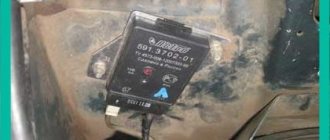
Checking the generator voltage regulator relay type 591 3702 01
The principle of checking the regulator type 591 3702 01 is identical to other devices of this type. You will also need to connect the products to a DC source and, by changing the output voltage values on the power supply, set the moment when the control lamp turns off.
A design feature of the type 591 3702 01 regulator is the output part, which has contacts designated “67” and “15”. Contact “67” is the “minus” of the system, so the corresponding wire from the power source, which is connected in series with the incandescent lamp, should be connected to it. Also, the negative contact should be connected to the “ground” of the regulator (metal mount). Contact “15” is the plus of the device, so the positive conductor should be connected to it.
The device is checked according to the standard procedure. First, the operating voltage is applied at which the light bulb should light. When the maximum possible voltage (14.5 V) is exceeded, the electric current in the circuit disappears.
More precisely, the relay-regulator type 591 3702 01 can be checked on a special diagnostic stand. This installation has a generator, battery and voltmeter. The regulator is connected on the stand in the same way as when installed on a car. After starting the stand, adjusting the rotation of the generator ensures that the voltage exceeds the cut-off threshold (14.5 V). The device shutdown is recorded by a voltmeter.
If the relay regulator does not turn off the voltage supply when a critical level is reached or there is no electric current immediately after starting the generator, then you will need to replace the relay regulator type 591 3702 01.
How to check a three-level voltage regulator relay
Instead of a standard relay-regulator, a three-level relay can be installed on cars. Such devices are more advanced and reliable. The difference between three-level relays and “chocolate bars” is the ability to arbitrarily set the cutoff voltage using the built-in regulator.
Testing a three-level relay is carried out according to the standard scheme, when an adjustable source of electric current and a test lamp are connected to the relay. When performing the test, only the previously set cut-off voltage limits should be taken into account. That is, if, using manual adjustment, the shutdown moment was set at 14.7 V, then at this voltage the disappearance of the electric current will be the norm.
Generator check
If an overcharge of the battery can be caused by a malfunction of the relay-regulator, then if the battery is undercharged, the part may be completely serviceable. Various generator breakdowns can cause a permanent or temporary lack of electrical current to fully restore the battery. If the car has a separate relay-regulator, then this part can be easily excluded from the electrical circuit and thus ensure that the generator is working properly. The diagnostic operation is performed with the engine running as follows:
- Disconnect the wires from the relay regulator (pins 15 and 67).
- Instead of a relay regulator, a 12 V incandescent lamp should be connected to the circuit.
- Disconnect the positive cable from the battery while the engine is running.
If the engine continues to run when the positive terminal is disconnected, then the car’s generator is working. Otherwise, you should check this part and all additional elements involved in the transmission of electrical energy.
How to remove the relay regulator
Removing the generator voltage regulator relay (“Lanos” or domestic “nine” is not important) is quite simple. It is worth noting that when replacing the voltage regulator, you only need one tool - a flat-head or Phillips screwdriver. There is no need to remove the generator or the belt and its drive. Most of the devices are located on the back cover of the generator, and are combined into a single unit with a brush mechanism. The most common breakdowns occur in several cases.
Firstly, when completely erasing the graphite brushes. Secondly, in case of breakdown of a semiconductor element. How to check the regulator will be discussed below. When removing, you will need to disconnect the battery. Disconnect the wire that connects the voltage regulator to the generator output. By unscrewing both mounting bolts, you can pull out the device body. But the voltage regulator relay for the VAZ 2101 generator has an outdated design - it is mounted in the engine compartment, separately from the brush assembly.
Purpose of the voltage regulator relay
Regardless of experience and driving style, the car owner cannot ensure the same engine speed at different times. That is, the crankshaft of the internal combustion engine, which transmits torque to the generator, rotates at different speeds. Accordingly, the generator produces different voltages, which is extremely dangerous for the battery and other consumers of the on-board network.
Therefore, replacing the alternator regulator relay should be done when the battery is undercharged or overcharged, the light is on, the headlights are flashing and other interruptions in the power supply to the on-board network.
Interconnection of car current sources
The vehicle contains at least two sources of electricity:
- battery - required at the moment of starting the internal combustion engine and the primary excitation of the generator winding; it does not create energy, but only consumes and accumulates at the time of recharging
- generator – powers the on-board network at any speed and recharges the battery only at high speeds
Rice. 2 In the car, the generator and battery are combined into a common network
Both of these sources must be connected to the on-board network for the correct operation of the engine and other electricity consumers. If the generator breaks down, the battery will last for a maximum of 2 hours, and without the battery, the engine driving the generator rotor will not start.
There are exceptions - for example, due to the residual magnetization of the excitation winding, the standard GAZ-21 generator starts on its own, subject to constant operation of the machine. You can start a car “from a pusher” if it has a DC generator installed; with an AC device, such a trick is impossible.
Rice. 3 Starting the internal combustion engine from the pusher
Voltage regulator tasks
From a school physics course, every car enthusiast should remember the principle of operation of a generator:
- when the frame and the surrounding magnetic field move mutually, an electromotive force arises in it
- The stators serve as the electromagnet of DC generators, the EMF, accordingly, arises in the armature, the current is removed from the collector rings
- In the alternating current generator, the armature is magnetized, electricity appears in the stator windings
Rice. 4 Operating principle of a car generator
In a simplified way, we can imagine that the magnitude of the voltage output from the generator is influenced by the value of the magnetic force and the speed of rotation of the field. The main problem of DC generators - burning and sticking of brushes when removing large currents from the armature - has been solved by switching to alternating current generators. The excitation current supplied to the rotor to excite magnetic induction is an order of magnitude lower, making it much easier to remove electricity from a stationary stator.
However, instead of terminals “–” and “+” constantly located in space, car manufacturers received a constant change in plus and minus. Recharging the battery with alternating current is not possible in principle, so it is first rectified with a diode bridge.
Rice. 5 Generator rectifier
From these nuances the tasks solved by the generator relay flow smoothly:
- adjusting the current in the excitation winding
- maintaining a range of 13.5 - 14.5 V in the on-board network and at the battery terminals
- cutting off the power to the excitation winding from the battery when the engine is turned off
Rice. 6 Purpose of the voltage regulator relay
Therefore, the voltage regulator is also called a charging relay, and the panel displays a warning light for the battery charging process. The design of alternating current generators includes a reverse current cut-off function by default.
Device check
The relay-regulator of the voltage of the VAZ 2106 generator, “kopecks”, and foreign cars is checked equally. As soon as you remove it, look at the brushes - they should be more than 5 millimeters long. If this parameter is different, the device must be replaced. To carry out diagnostics, you will need a constant voltage source. It would be desirable to be able to change the output characteristic. You can use a battery and a couple of AA batteries as a power source. You also need a lamp, it must run on 12 Volts. You can use a voltmeter instead. Connect the plus from the power supply to the voltage regulator connector.
Accordingly, connect the negative contact to the common plate of the device. Connect a light bulb or voltmeter to the brushes. In this state, voltage should be present between the brushes if 12-13 Volts are supplied to the input. But if you supply more than 15 Volts to the input, there should be no voltage between the brushes. This is a sign that the device is working properly. And it doesn’t matter at all whether the voltage regulator relay of the VAZ 2107 generator or another car is diagnosed. If the control lamp lights up at any voltage value or does not light up at all, it means that there is a malfunction of the unit.
Diagnostics of an automobile relay-regulator
First, you need to decide whether checking the relay is necessary at all. First of all, pay attention to incorrect charging of the battery:
- Overcharging is observed . The electrolyte begins to boil away, and the acid solution may fall on body parts;
- Undercharging is observed . The battery charge is constantly low, as a result of which the engine may not start, and the optics may remain incandescent.
If you observe any of the above, you need to get a tester and start checking the relay regulator. In short, any voltage deviation from the maximum (14.5, in rare cars as much as 14.8 Volts) or minimum (12.8 Volts) at the corresponding speeds indicates the need to replace the relay regulator. Before diagnosing, it is worth measuring the voltage at the terminals of the car battery - normally it is 12.8 Volts.
If the vehicle uses a built-in relay, you need to do the following:
- Remove the brush assembly and, if necessary, select new brushes. Brushes less than 5 millimeters are considered short;
- Take the power source. A power supply or charger that allows you to regulate the voltage to at least 16 Volts . Connect the negative wire of the source to the corresponding terminal of the regulator;
- The “positive” wire of the power source is connected to the corresponding terminal of the relay regulator;
- Connect a 10-watt test lamp to the brushes. If it is not available, an LED will do;
- Apply power from the source to the relay, gradually increasing the voltage. As soon as it exceeds 14.5 or 14.8 Volts (exceptional case), the lamp/LED should go out.
If the relay regulator does not pass the test (the control device does not go out), it is definitely worth changing. If you ignore the problem, the battery will be overcharged on a constant basis, which will eventually lead to its failure. In the case of a built-in relay, checking will become even easier:
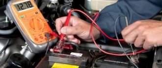
- Connect the tester probes to the relay terminals;
- Set the multimeter to 20 Volts ;
- Start the engine and check the voltage indicator - it should be minimal (about 12.8 Volts);
- Increase engine speed. Voltage readings should increase smoothly;
- When the engine is at 3500 rpm , monitor changes in voltage readings. They must fall into the range of 14-14.5 Volts. In some cars the maximum is 14.8 volts.
If you observed serious deviations or, on the contrary, constant voltage regardless of the speed, the relay regulator is clearly faulty. We strongly recommend that even after these checks, you check the regulator terminals once again - oxides and deposits can interfere with correct diagnostics of the device. After cleaning, the diagnosis should be repeated.
conclusions
In the electrical system of a car, the voltage regulator relay of the Bosch generator (as, indeed, of any other company) plays a very important role. Monitor its condition as often as possible and check for damage and defects. Cases of failure of such a device are not uncommon. In this case, in the best case, the battery will be discharged. And in the worst case, the supply voltage in the on-board network may increase. This will lead to the failure of most electricity consumers. In addition, the generator itself may fail. And its repair will cost a tidy sum, and considering that the battery will fail very quickly, the costs will be astronomical. It is also worth noting that the Bosch generator voltage regulator relay is one of the leaders in sales. It has high reliability and durability, and its characteristics are as stable as possible.
Repair or replacement of the voltage regulator - what to choose
When various parts fail, the driver often makes a difficult decision: repair the part and install a new one. With a car relay regulator, such a dilemma arises only when using a car that was produced several decades ago. It is almost impossible to purchase new spare parts for rare car models, and disassembled parts may be of dubious quality. When an integrated device (chocolate bar) is used to adjust the battery charge level, such a device cannot be repaired. The parts installed in relay regulators of this type can be restored, but this work will require certain knowledge and skills, as well as significant time investment.
Replacing the generator relay regulator
If the relay regulator can no longer be used for its intended purpose, then a new part should be installed. The combined element changes in the following sequence:
- Disconnect the negative terminal of the battery.
- Disconnect the fasteners.
- Remove the brush assembly cover.
- Disconnect the diode bridge.
- Unscrew the contact group nuts.
- Unscrew the threaded elements holding the regulator.
- Remove the part.
Installation of a new regulator is carried out in the reverse order of removal. When performing this operation, the element contacts must be connected correctly.
Depending on the generator model, the process of replacing the relay regulator may differ slightly. The main thing is to perform dismantling, if possible, without damaging other elements of the generator set.
Replacing an individual element is much easier. For this purpose, it is enough to disconnect the main 2 contacts from the device, remove the product from the car body and install a new part in its place. Then correctly connect the previously removed wires and check the operation of the device. To do this, just start the engine and measure the voltage at the battery terminals at different speeds.
Voltage regulator repair
You can try to disassemble and repair old models of relay regulators that are installed separately. It should immediately be noted that such an activity has little promise, but if you ring the internal elements with a multimeter and find the burnt part, you can completely restore the functionality of the regulator.
Repairing the regulator relay can take too much time, so it is much easier and more correct to purchase a new product or remove the device from another car in which this part is in known good condition.
To find out whether a car relay-regulator is working correctly or not, it is enough to carry out simple diagnostics using a multimeter or a test lamp. If the device being tested does not show signs of life, then it is enough to change the part to restore the functionality of the electrical system. Repairing a “chocolate” or “tablet” is practically impossible, but other types of regulators can also be restored with great difficulty. Therefore, if the battery is not charging or too much voltage is supplied to the battery, you need to purchase a new product from a specialized store.