The location of the relays and fuses, as well as the differences in the mounting blocks, is here www.drive2.ru/b/538898/
Scheme of VAZ-2108, 2109 with a low instrument panel (early versions)
content-5.foto.my.mail.ru…hofer2107/1348/s-3867.jpg There is a “parking light” function - turning on the left or right lights in the parking lot.
Scheme of VAZ-2108, 2109, 21099 with a low panel (later versions)
content-21.foto.my.mail.r…hofer2107/1348/s-3815.jpg There is no brake pad wear sensor (previously, the handbrake lamp blinked when the lever was raised, and came on constantly when the sensors on the brake pads were activated).
Years of production 2108: 1984—2003 in Russia, 2003—2014 in Ukraine
Scheme of VAZ-2108, 2109, 21099 with a high panel and Euro fuse block 2114
content-21.foto.my.mail.r…hofer2107/1348/s-3812.jpg Fog lights, central locking, heated seats and electric windows.
Years of production 2109: 1987-2004 - in Russia, 2004-2011 - in Ukraine
Connection diagram for headlight cleaners on low and high panels of cars produced after 1989
content.foto.my.mail.ru/m…hofer2107/1348/h-3928.jpg The headlight cleaners are turned on with a button, in place of the relay there is a jumper.
Years of production 21099: 1990-2004 - in Russia, 2004-2011 - in Ukraine
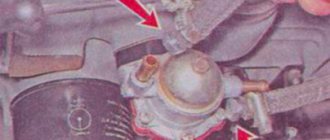
Diagram of a mixture control system with a controller under the hood
content-10.foto.my.mail.r…hofer2107/1348/s-3906.jpg
Diagram for switching on fog lights since 2000 on a high panel
Since 2000, in accordance with UNECE rule 48-01, the electrical circuit for switching on the rear fog lights has been changed on parts of VAZ vehicles. Added rear fog light relay 2114-3747610, and rear fog light switch 21093-3710030-10 (like a regular one, only without fixing). Instrument panel harness used 21099-3724030
We are reworking the activation of the rear fog lights according to the latest scheme. That is, the button will not be fixed: if the headlights or front fog lights are on, press and release the button for the rear fog lights - they turn on. They turn off when you press the button again or automatically when you turn off the headlights. That is, we will never forget to turn them off. For high panel. You need rear fog lamp relay 2114-3747610. It may look different, it is also used on the VAZ-2114, 2110, GAZ-3110... It is advisable to find a connector for it, you can just wrap the usual terminals with electrical tape and stick it in.
Comments 10
I can’t find this, where the green one comes in and where it goes
The green one goes to the size button, light switch, can go to the fuse for the rear fog light button (it is located right next to the button) or can connect to the 3/8 mounting block. In this case, power went to the headlight cleaner fuse and from it to sh3/21 from which power went to the button. That is, in the second option, the fuse in the mounting block is responsible for the headlight wipers (if any) and for the rear fog lights and there is no fuse next to the button. In the second option, there is not a green wire going to the button, but an orange-white one. In the photo ad-cd.net/169d0das-480.jpg the top two pictures are options for connecting the button. So there may not be any green. We check the power on the green or orange-white wire of the button when the ignition and headlights are turned on.
I have an old-style mounting block, can it affect anything?
If you put the wiring under a new type of mounting block, it will not work. Does the button have a green or orange/white wire?
Hi, I had a 21099 96 with a low panel before they changed it to a high one, I can’t do the rear PTF, there are no these wires, what should I do?
I advise you to start by looking for the connector for the button next to the stove control levers where it was on the low panel, maybe it is still there. Then you need to extend it and connect the indicator light next to it (to the black and orange-black).
If there is no connector, then here is a diagram for connecting the rear PTF ad-cd.net/6584a32s-960.jpg Take the button. Contacts 7 to black and 6 to white to the same wires of the glass heating button (backlight), contact 10 through a 10 Amp fuse to the green side button, and contact 9 to the indication light (its second contact is to the black contact 7 of the button, this is a minus) and to orange -black wire for wiring to the rear lights. The wiring runs to the left of the clutch pedal from the mounting block to the floor. You need to find the orange-black wire there, cut it and connect it to the button, or you can press the lock of its terminal and pull it out of plug 9 of the mounting block.
Thank you for such a complete and clear answer)) we will try
I advise you to start by looking for the connector for the button next to the stove control levers where it was on the low panel, maybe it is still there. Then you need to extend it and connect the indicator light next to it (to the black and orange-black).
If there is no connector, then here is a diagram for connecting the rear PTF ad-cd.net/6584a32s-960.jpg Take the button. Contacts 7 to black and 6 to white to the same wires of the glass heating button (backlight), contact 10 through a 10 Amp fuse to the green side button, and contact 9 to the indication light (its second contact is to the black contact 7 of the button, this is a minus) and to orange -black wire for wiring to the rear lights. The wiring runs to the left of the clutch pedal from the mounting block to the floor. You need to find the orange-black wire there, cut it and connect it to the button, or you can press the lock of its terminal and pull it out of plug 9 of the mounting block.
What kind of problems does an electrical circuit help to solve?
The electrical circuit for the VAZ-2109 injector is, of course, several times more complicated than for carburetor cars. However, this is not at all surprising, because models with distributed fuel injection have numerous electronic devices built into them, which, unfortunately, can fail. An interactive diagram helps solve many problems:
- provides the driver with information about the functionality of all electronic devices;
- transmits a control pulse to electronic elements;
- acts as electrical protection for all electronic devices;
- protects the system from short circuits.
Injection motor
As for injection internal combustion engines with injectors, their malfunctions, as practice shows, are usually associated with failure of the sensors or the electrics themselves.
To diagnose the cause of the malfunction, do the following:
- first of all, you need to disconnect the power wire from the sensor you suspect;
- after that, using an ohmmeter, you need to measure the resistance on the contacts;
- the resistance value must be checked with the nominal value, which should be indicated in the service book for the car.
Types of electrical circuits
There are several options for circuits for monitoring the condition of electrical equipment of the VAZ-2109:
- With a "high panel". This scheme is considered as the most interactive and relevant. It provides an additional circuit that is intended for an automotive mounting block.
- With a "low panel". This circuit is used to identify a malfunction in the automotive mounting block.
- With Europanel. This version of the diagrams provides complete information for both the internal diagram and the mounting block. It also includes a diagram that helps to connect a Europanel, that is, electrical devices and appliances created according to the “Euro” type.
What's inside the cabin
Replacing the power unit will also require replacing the interior wiring.
Many owners combine this process with replacing the instrument panel with a modern one:
- the “high” panel from the VAZ 21099 fits without modification;
- The “LUX” panel from the VAZ 2114 model is suitable with minor modifications.
Tip: there are a lot of videos on the Internet that describe in detail the process of finalizing the panel. Read them all carefully before starting work on your car.
How the signal is transmitted
From the electronic unit, a signal is transmitted through special wires, which are painted in different colors, to the system that controls the functionality of the engine.
Thanks to the different color markings of the wires, the driver can understand the electrical circuit and find exactly the wire that is needed to solve a particular problem. To ensure high-quality and uninterrupted transmission of the electrical signal, you must do the following:
- use wires with a suitable cross-section;
- monitor the contact resistance, which should be minimal for removable connections;
- monitor the integrity of the insulation of electrical conductors.
The operation of the VAZ-2109 injector engine, as well as its dynamic characteristics, is primarily affected by the condition of the electrical wiring, therefore, it must be constantly and carefully monitored.
Having familiarized yourself with the intelligent color wiring diagram, even without the presence of a special measuring device, you can quite easily independently find a fault in the electrical wiring, even the most insignificant one. Eg:
- find out why the ignition stopped working;
- determine why the starter does not turn on;
- due to which the generator lacks voltage;
- which led to a breakdown of the heating system.
If the cross-section of the conductor decreases, this will lead to a deterioration in the transmitted electrical signal, which will subsequently increase the temperature. Sometimes an external examination will not help to identify a violation of the integrity of the veins, and only a deep examination will help to identify such destruction. The integrity of the wiring is compromised due to oxidation of the contacts, and since such a process is inevitable when operating machines, this means that they need to be cleaned periodically.
If the electrical signal is supplied in a distorted form, then the malfunction will be felt throughout the entire VAZ-2109 injector system.
Carburetor engine
The VAZ 2109 wiring diagram can work differently, depending on the type of engine, in particular, we are talking about starting the power unit:
- When the ignition is turned on, a charge is supplied to the battery terminals through the high-voltage wiring harness. In this case, the driver will be able to turn on music, lighting, and indicators will appear on the control panel.
- After this, the starter unit rotates the crankshaft and the entire piston group. As a result, the generator starts.
- Next, power begins to flow to the ignition coil, which, in turn, produces high-voltage voltage. This charge is transferred through the wires to the switchgear, while the device continues to function.
- The engine crankshaft then begins to rotate the distributor drive. The contacts close on the device, as a result of which the charge begins to flow to the spark plugs. The flammable mixture ignites, which leads to the engine starting (the author of the video is NIKOLAY GOROSHKO).
Additional tips from the professionals
By taking into account some tips and tricks provided by professionals, you can independently extend the life of your car wiring:
- car owners must periodically inspect the external condition of the insulation and all connectors by looking under the hood of their car;
- If a minor defect is discovered during inspection, the damaged wire must be replaced to prevent a short circuit. If the break is insignificant, then you can wrap it with high-quality electrical tape for a while, but it is not recommended to postpone replacement for a long time;
- A special product, WD-40, which can be purchased at an affordable price in a specialized store, will help remove the oxidizing layer from the surface of the connector;
- It is advisable to make additional protection for the engine crankcase to prevent moisture from getting on the wires.
It is imperative to wipe off excess oil from the insulation to extend its service life. Experts strongly recommend replacing old or damaged wiring rather than repairing it, in order to avoid more serious breakdowns in the future, which will cost car owners several times more.
Schematic electrical diagrams, connecting devices and pinouts of connectors
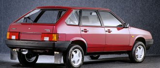
The VAZ-2109 car was produced at AvtoVAZ from 1987 to 1997. Years of production 21099: 1990-2004 - in Russia, 2004-2011 - in Ukraine. Here are colored wiring diagrams (for the injector and carburetor) with a description of all the elements for various modifications. The information is intended for self-repair of cars. Electrical circuits are divided into several blocks for ease of viewing via a computer or smartphone; there are also circuits in the form of a single picture with a description of the elements - for printing on a printer.
Injection motor
Injectors differ from the internal combustion engines described above in the presence of many electronic devices. In the case of an injector, failures are usually related to the operation of the sensors or the wiring itself.
To accurately identify the cause of an injector failure, you must perform the following steps:
- first disconnect the cable from the sensor;
- then, using an ohmmeter, measure the resistance level;
- After this, the received data will need to be checked with that indicated in the table in the car’s operating instructions.
Modifications of VAZ-2109
VAZ-2109 . The basic model, which was produced from 1987 to 1997, was equipped with a 1.3-liter VAZ-2108 carburetor engine with a capacity of 64 horsepower.
VAZ-21091 . Modification of a car with a derated VAZ-21081 engine, 1.1 liter and 54 horsepower. It was mass-produced from 1987 to 1997.
VAZ-21093 . Modification of a car with a VAZ-21083 carburetor engine, 1.5 liters and 73.4 horsepower. Serially produced from 1988 to 2006.
VAZ-21093i . Modification with a VAZ-2111-80 injection engine, 1.5 liters. the first prototype appeared in 1994, mass production began in November 1998.
VAZ 21093-22 . Model made specifically for the Finnish market. It features improved interior trim, pre-installed alloy wheels and a new dashboard. The car was equipped with a 1.5 liter injection engine. Produced from 1995 to 1998.
VAZ-210934 . An all-wheel drive SUV with a VAZ-21093 body mounted on a Niva frame, on which the suspension, steering, engine, gearbox and transfer case from the same VAZ-2121 Niva model were already installed.
VAZ 2109-90 . A variant of the car, which was equipped with a compact two-section Wankel rotary piston engine with a volume of 654 cm3.
VAZ-21096 . Export modification of the VAZ-2109 for countries with left-hand traffic, the steering column was located on the right.
VAZ 21097 . Export modification of VAZ 21091 with right-hand drive.
VAZ 21098 . Another export modification, but this time the VAZ 21093 model with a right-hand steering column.
VAZ-2109 Carlota . A car produced from 1991 to 1996 in Belgium by Scaldia-Volga.
VAZ-21099 . The next independent car model, which is a modification of the “nine”. This car had a 4-door, 5-seater sedan body and a rear overhang extended by 200 mm.
Preparatory work
There are several options for injection systems on the market, but the best one is BOSCH M 1.5.4. It has excellent quality, high reliability, and most importantly, a low price. In any case, you will have to purchase some parts on the secondary market. The main elements that also need to be purchased:
- air filter housing;
- intake manifold for the VAZ 2109 injection system;
- fuel tank;
- ramp;
- generator from the VAZ 2110 model or similar;
- fuel pump;
- wires, sensors, actuators.
Before installing new equipment, it is necessary to dismantle the generator, cooling pipes and hoses, thermostat, and gas tank. The fuel tank must be washed and dried before installation.
The ignition module is installed in the engine compartment on the front side of the engine. You will have to make a bracket that is attached to the body. There should be a knock sensor on the engine block (between the second and third cylinders). Then replace the pipes, thermostat, and pulley. The latter must be damping; to install it, you will have to drain the oil and remove the engine sump.
Wiring diagram for VAZ-2109 carburetor
- Headlight.
- Electric motor for headlight glass cleaning system. An optional part, used mainly on export vehicles.
- Limit switch for powering the engine compartment lamp.
- Klaxon.
- An electric motor drives a fan installed on the radiator of the cooling system.
- Temperature indicator that provides a control signal for the electric drive of the fan impeller.
- Alternator.
- Fluid supply valve for headlight glasses. Used in conjunction with paragraph 2.
- Fluid supply valve for the glass of the fifth door.
- Fluid supply valve to the front glass.
- Spark plugs.
- Hall sensor used to distribute ignition pulses.
- Coil.
- Limit switch for reverse gear lights.
- Fluid temperature meter in the cooling system.
- Starter.
- Accumulator battery.
- A sensor that measures the fluid level in the brake booster.
- Switch that controls the ignition system.
- Sensor for determining the position of the top dead center of the piston of the first cylinder. Installed on some export VAZ 2109 with a diagnostic system. Found only on cars before 1995.
- Diagnostic block. Optional element, installed together with item 20.
- Controller for controlling the solenoid valve installed in the carburetor.
- Starter switch contact block.
- Limit switch on the carburetor.
- Economizer valve.
- Sensor signaling an emergency decrease in oil pressure.
- Washer pump drive.
- Fan impeller motor for ventilation and heating systems.
- Resistance providing additional fan speeds.
- Speed shifter.
- Windshield wiper drive.
- Cigarette lighter.
- Illumination system for levers for adjusting heater operating parameters.
- Socket for additional equipment.
- Lamp for auxiliary lighting of the engine compartment.
- Illumination system for the glove box on the instrument panel.
- Relay and fuse link mounting block.
- Instrument panel light switch.
- Parking brake lamp limit switch.
- Brake lamp limit switch.
- Steering column switch lever block.
- Exterior lamp switch.
- Hazard switch.
- Turn on the rear fog lamp.
- Bimetallic fog lamp fuse.
- Heated glass switch on the fifth door.
- Turn signal repeaters on the front fenders.
- Central interior lighting.
- Individual lampshade.
- Switches for backlight operation on the middle pillars.
- Ignition switching unit.
- Egnition lock.
- “Low” type instrument cluster.
- Choke limit switch on the carburetor.
- Rear lights.
- Fuel level meter in the tank.
- Heated glass.
- Rear wiper drive.
- Two lamps for room illumination.
Wiring diagram VAZ-2109 carburetor - full view:
All carburetor “nines” use the same non-contact ignition system, built on the basis of an electronic switch and a Hall sensor.
The failure of the electronics control unit, which is typical for the Nine, occurs due to the fact that the housing allows water, dust and moisture in the form of condensation to pass through. The factory provided a tiny groove to drain water from the housing, but it constantly gets clogged, the housing fills with water, and the control unit slowly fails.
Main reasons for refusal
If the engine does not want to start, but the starter rotates the crankshaft, then the main reasons are known:
- Either the air-fuel mixture is not supplied to the cylinders;
- Either there is no one to “ignite” this very mixture - there is no spark.
Supply system
Checking whether fuel is getting into the cylinders is quite simple. For this:
- We take a spark plug wrench from the standard tool kit;
- Remove the high-voltage wire from the spark plug of the first cylinder;
- We unscrew the spark plug with our own hands;
- We look at it carefully.
Tip: if the spark plug is wet and smells of gasoline, it means the air-fuel mixture is entering the cylinders. You should look for the reason for the refusal. If not, then you need to look for the cause in the power system components. Videos about eliminating such failures are available on the Internet.
Ignition system
The first step in troubleshooting should be to start by testing the ignition system, since quite a lot of devices take part in the sparking process:
- Spark plug;
- High voltage wires;
- Ignition distributor (on carburetor engines);
- Hall Sensor;
- Switch;
- Ignition coil.
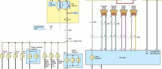
Equipment diagram for VAZ-2109 injector
The VAZ 2109 wiring for the injector has many connectors for connecting sensors to the computer.
- TPS (throttle position sensor);
- DPKV (crankshaft position sensor);
- DT (temperature sensor);
- DSA (vehicle speed sensor);
- Canister purge valve;
- MAF (mass air flow sensor);
- DD (knock sensor) and others.
The weak point of the harnesses is the power wiring on the bottom shelf of the radiator, which is constantly exposed to high temperatures and in this place it is in no way protected from water and dirt. Another problem is a harness under the carpet next to the driver's seat. Moisture constantly accumulates there, and in order to remove it, you need to dry the floor, inevitably tugging on the rope.
Since the mid-90s, VAZ 2109 began to use engines with an injection system, which greatly changed the electrical layout of the engine compartment and instrument panel. Below is an electrical diagram of a 1999 car with an ECM type GM ISFI-2S and January 4/4.1.
Engine compartment modifications
In addition to replacing the power unit after it has exhausted its life, there are many components in the engine compartment whose wiring also needs to be replaced:
- high-voltage wires from the ignition unit;
- wiring of various control sensors;
- battery power cables (connections are most susceptible to corrosion).
Numerous sensors in the engine compartment require special monitoring:
- Coolant temperature sensor - if the electrical wiring is faulty, the driver will not notice overheating of the power unit;
- Brake fluid level sensor in the expansion tank - a leak or low level can lead to brake system failure;
- ABC system sensors - oxidation of contacts or disruption of wiring integrity can lead to system failure;
- Exhaust gas sensor - based on its readings, the electronic unit “prepares” the fuel-air mixture. If the sensor does not work, gasoline consumption will increase.
A useful addition to the functionality of the car is the acquisition of a modern anti-theft system.
Installing a modern alarm system is a special topic, since its work affects several main components and systems of a VAZ family car:
- General electrical system;
- Supply system;
- Sound and light circuit and actuators (side lights, headlights, sound signals);
- Standard immobilizer.
Advice: often manufacturers of alarm systems accompany the installation process with video and photo materials for each specific model of a particular family of cars. Before starting installation, you should read them carefully.
General alterations
Installing additional fog lights is a general modification because:
- Affects equipment in the engine compartment;
- Interferes with the instrument panel inside the cabin;
- Connects to the vehicle's standard power supply system;
- Attached to the power body.
To install and connect fog lights, you will need a wiring diagram for the VAZ 2109, because the package includes:
- Connecting wires;
- Terminal blocks;
- Switching relay;
- Actuators (buttons);
- A backlight lamp (or LED) indicating the status of lighting fixtures.
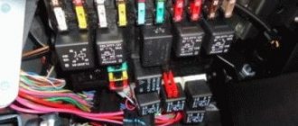
Relay and fuse box diagram 2109
The fuse blocks do not depend on the fuel injection system used - carburetor or injector. BP will differ only by year of manufacture of the car. That is, the mounting blocks for the carburetor and injector are the same. The VAZ 2109-099 fuse box (carburetor, injector) is located under the hood, in the compartment in front of the windshield on the left side.
Fuse block 2114-3722010-18
K1-relay for turning on headlight cleaners; K2-relay-breaker for direction indicators and hazard warning lights; K3 - windshield wiper relay; K4-relay for monitoring the health of lamps; K5-power window relay; K6 - relay for turning on sound signals; K7-relay for turning on the electric heating of the rear window; K8-relay for high beam headlights; K9-relay for low beam headlights; F1-F16 - fuses.
Fuse block 2114-3722010-60
K1 - Headlight wiper relay, K2 - Turn signal and hazard warning relay, K3 - Windshield wiper relay, K4 - Brake light and parking light relay, K5 - Power window relay, K6 - Horn relay , K7 - Rear window heating relay, K8 - Headlight high beam relay, K9 - Headlight low beam relay, F1 - F16 - Fuses, F1 - F20 - Spare fuses.
Attention! The power terminals on the generator often become loose, heat up, spark and melt the wiring. Pay attention to this point when searching for possible faults yourself.
Useful tips
The VAZ 2109 wiring diagram is necessary without any intention of making changes to the car’s structure, because during operation the wiring is subject to:
- Temperature effects - both climate changes and daily heating and cooling cycles;
- Mechanical loads - wiring runs throughout the entire car body, exposed to components and mechanisms, passengers and transported goods
Accordingly, the owner is required to perform a preventive inspection of the standard wiring in order to identify insulation violations and mechanical damage. Timely detection of a malfunction will allow you to quickly correct and prevent more significant failures in the operation of the vehicle’s electronic devices.
Conclusions: we hope that the issues covered in this article will protect you from thoughtless intervention in the electrical circuit of your car. And if you need to replace the standard wiring, you will do it in accordance with the manufacturer’s recommendations.
Maintenance
Repair manual for VAZ 2108, 2109, 2114, 2115 Wires and fuses
The operation of domestic cars has national characteristics:
- owners prefer to maintain and repair their cars with their own hands;
- This requires a detailed diagram of the main systems.
In the video presented in the article you can see which components and electrical circuits require constant monitoring by the owners.
https://youtube.com/watch?v=pxeWlEvePvI
Conclusions: cars of the VAZ 21093 family still serve today, delighting owners with their reliability. And any failures can be easily corrected yourself, having a detailed electrical wiring diagram at hand.
Methods for tuning the power unit
There are many ways to improve engine performance. Before work, keep in mind that in case of an error you will have to completely change the unit. Each method of changing motor characteristics has its own advantages and disadvantages. Here are a few relatively safe tuning methods:
- Installing a zero resistance filter. Craftsmen often call this component “zero”. If you choose the right filter, the dynamic performance and motor power will increase by 5%. If you equip your car with a zero drive, then you will have to carefully monitor it and clean it in a timely manner. Otherwise, installing the element will be pointless and dangerous. A dirty filter poses a risk of engine damage. Focus on a price of 5 to 6 thousand rubles per filter. Instances that cost less will not work normally.
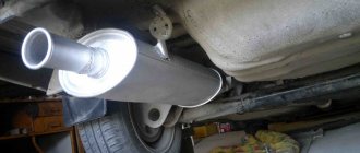
- Together with injection power units, it is often recommended to use direct-flow mufflers. This part should only be used in the gas exhaust system if you have carried out a thorough modernization of the engine. Another option when such a muffler would be appropriate: if the car has a turbo air injection system (additional compressor). The straight-through muffler will only affect power in conjunction with other upgrades. In other cases, installing it is a pointless waste of money. It will make the car noisier and a roar will be heard when driving.
- Another effective way to increase engine power is to install a sports range on the gearbox. At the same time, a 6th gear will be added, and the car will accelerate more dynamically due to a change in a number of gear ratios. The overall engine power will not change, but the dynamic characteristics will become noticeably better. At the same time, replace the piston group and install a more powerful engine. Deep reworking of the engine and gearbox will allow for a qualitative change in the power plant. You will feel the dynamics already when you first start the engine and accelerate. Such tuning will be expensive, but it will be worth it.
- Chip tuning is most often recommended for injectors. Using a simple laptop, a small amount of equipment and application programs, the ECU is configured. The advantage of this method is its low cost - you do not have to carry out mechanical work or interfere with the elements of the unit. If you make a mistake, it will be enough to replace the on-board computer. It will cost less than replacing an engine if another type of tuning fails. After flashing the ECU, you will immediately notice a change in engine performance.
Preparation
Fuel level sensor FLS for VAZ 2108, 2109, 21099 cars
At the preparatory stage, which is short but very important, it is worth completely de-energizing the car by disconnecting the battery. You also need to remove all hoses, speed and clutch sensors
Be sure to drain the oil from the engine crankcase and the liquid that cools the radiator. Removing the engine without removing the gearbox:
- first of all, you need to put a reliable support under the car, preferably wooden stumps;
- unscrew the left crab, move the stretcher to the side;
- remove the generator from the engine;
- remove the tensioner pin, pump, distributor and receiving pipe;
- do not forget to remove the head if you are planning a major overhaul;
- the motor must be removed from the box and lowered to the floor;
- in order to get the engine, you need to raise the front part higher (this is done using a jack);
- you can also just pull everything through the top.
How to remove the engine from the gearbox:
- The first thing you need to do is turn off the power to the car. To do this, disconnect the battery. It’s easy to check the lack of current, try turning on the wipers;
- Drain the oil from the engine crankcase. A warm engine will speed up the process;
- drain the coolant from the cooling system, here you need a cold engine;
- get rid of the engine crankcase and exhaust pipe protection;
- carefully disconnect all hoses;
- Next, you need to unscrew the ground wire fastening nut. Next, you can safely turn off the thermostat;
- disconnect the central high voltage from the ignition distributor. To do this, you need to release the pad lock and remove it;
- remove the drive cable from the clutch lever;
- next, you should disconnect the starter supply wires;
- turn off the generator;
- disconnect the wires from the coolant temperature and oil pressure sensors;
- further work will take place under the car. To make it as comfortable and safe as possible, it is worth acquiring an overpass;
- At this stage, unscrew the drive rod mounting nuts. Disconnect the speedometer drive rod, disconnect the power wires;
- disconnect the two braces, tie rods and ball joint from the lever;
- Move the upper tail of the drive a little and push it out with a pry bar. Insert the technological plug into the vacant space;
- Next comes the stage of dismantling the engine. We fix it with a strong rope using the eyelets (rings). It doesn't hurt if you take the time to check their strength first;
- It is best to remove it through the top, but you can also get it through the bottom. Then lower the engine to the floor and lift the front of the car using a jack;
- After you have secured the engine with ropes, you can reach it through the top.
Remember that you need to act extremely carefully so as not to lose the motor, scratch the body, or damage parts. As you can see, the process is very complicated.
Successful dismantling is possible only if all points of the instructions are followed, you have deep knowledge, extreme caution and no haste.
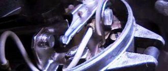
Features of the ignition module
Now let's talk about a more complex issue - the ignition module and its design features.
The design includes several components, each of which has its own nuances.
| Component | Peculiarities |
| Ignition coil | There are always two coils on a VAZ 2109. This mechanism is responsible for generating current |
| High voltage switches | Switch keys also work together. Through them, the current goes to the spark plugs, plus the controller regulates the time the current is turned on, which is calculated by receiving information from the crankshaft sensor |
| Electronic control unit | Responsible for distributing information in the form of electronic impulses |
| Frame | High-strength plastic is used for its manufacture, which largely ensures the durability and reliability of the device. |
Ignition coil
Location
Any work related to repair, testing, and maintenance of the ignition module will be impossible to perform if you do not know basic things - the location of the device.
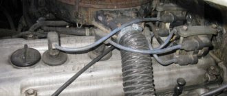
You can find the ignition module (ignition module) in the engine compartment. Find the high voltage wires that go to the spark plugs. One end is connected to them, and the other goes to the module. The MZ is small in size and enclosed in a plastic housing.
Device location
Principle of operation
Initially, on carburetor cars, the system worked due to the presence of an ignition coil. With injectors everything is somewhat different.
- Initially, the ignition coil is turned on, generating a high voltage current. The coil operates on the principle of magnetic induction;
- Then the electronic control unit MZ is connected to the work, performing the functions of control, transmitting commands, and ensuring the flow of current required by the characteristics to the spark plugs;
- Next, the spark plugs activate the spark, ignition occurs, and so on.
MH malfunctions
The ignition module often shows the most basic sign of failure - lack of spark. But this is not the only indicator of a malfunction. These also include:
- Lack of dynamics when accelerating the car. Trying to quickly pick up speed, you can clearly feel failures in engine operation;
- The engine does not produce the usual power; in some cases, the engine is not able to pull the car uphill;
- The idle speed fluctuates;
- One of the pairs of engine cylinders refuses to work. Here, most likely, there is no current that should come from the ignition coil.
To eliminate problems with the MH, the first thing you need to do is check the spark plugs, and then make sure the other elements are working.
Disconnect and check
Checking the spark plugs
To check the condition of the spark plugs, which may cause the module to malfunction, you need to:
- Unscrew the spark plugs from their seats, having first removed the high-voltage wires. The elements are removed with a special key.
- Inspect the spark plugs for carbon deposits, mechanical defects, and poor clearance.
- Send defective spark plugs to a landfill and install new ones in their place.
If replacing or cleaning the spark plugs does not produce results, then the reason lies in other elements of the ignition module.