09 February 2015 Lada.Online 245 419 96
In order for the car to comply with more stringent environmental standards, AVTOVAZ equips modern Lada cars (Priora, Granta, Kalina, Niva, Largus, Vesta and XRAY) with an electronic gas pedal or “E-gas”. The throttle valve drive got rid of the cable and became equipped with a gear motor. As a result, the gas pedal has no mechanical connection with the throttle valve, and engine control has become completely electronic.
Niva with ECM
As you know, the first Russian SUV Niva was born back in the days of the Soviet Union. At that time, in the USSR they did not even think about an electronic engine control system; the entire process of operation of the internal combustion engine was mechanical. The engine was supplied with fuel through a carburetor. At present, the Niva still continues to be produced, but with its ancestors, the modern Niva has only the body left and it has undergone minor modifications.
The carburetor was replaced with an injector, the interior was changed and the appearance of the car was transformed, but still the Niva remained Niva. The legendary Niva cross-country ability did not deteriorate after these modifications, but became much more comfortable.
In this article we will talk about the sensors of the engine control system in the injection Niva, namely, it describes in detail each of the sensors, where it is located and what function it is responsible for, as well as the signs of sensor malfunction are described in detail.
Benefits of Execution
Chip tuning of the Chevrolet Niva engine allows you to obtain many tangible advantages:
significantly increase engine power - turbocharged power plants are strengthened by almost 35%, engines in which turbocharging is not provided - by almost 7%;
provided that an experienced specialist is involved in the work, carry out all operations as quickly as possible;
significantly increase dynamic acceleration performance;
using firmware, you can remove those restrictive settings that prevent the vehicle from accelerating to maximum speed;
Now you can reconfigure the engine, change the type of fuel it consumes, for example, AI - 92 to AI -95.
After flashing the Chevrolet Niva ECU, you can always return to the factory settings.
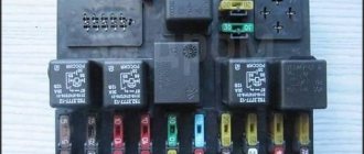
Electronic engine control unit (ECU)
An ECU is a kind of computer in a car; it is in this device that the entire operation of the internal combustion engine is corrected. All sensors that are installed in the car transmit readings specifically to this unit, and based on the readings, it makes changes to the operation of the engine, which affects both the engine speed and its consumption.
Symptoms of ECU malfunction:
There can be a huge number of signs of malfunction of this unit, because signs of failure of one sensor may even indicate failure of the unit.
Firmware performance
Successful implementation of such tuning will lead to the following results:
fuel will be saved significantly, ranging from one and a half to two liters per 100 km;
engine functionality will improve;
the machine will run smoothly, without jerking.
To perform flashing, use the ChipExplorer editor, which is available for download on the Internet. Such a program is offered for sale in a car dealership. It is important to know how such tuning is performed. If you lack confidence in your abilities, it is better to seek professional help.
Mass air flow sensor (MAF)
This sensor is located near the Niva air filter box. Air flows through this sensor, which is necessary to form the air-fuel mixture. The sensor records the amount of air passing through it and sends signals to the electronic engine control unit (ECU).
Signs of a DMRV malfunction:
- Loss of vehicle dynamics;
- Increased fuel consumption;
- Unstable idling (speeds fluctuate);
- Difficulty starting the engine when the engine is warm;
Signs of malfunction and methods of failure
Like any car part, the sensor is subject to vibration and is susceptible to contamination and oxidation. Therefore, its failure is possible from time to time. To understand the cause of the breakdown and what to do in each specific situation, the following problems should be eliminated:
- broken wiring
- the appearance of oxide on the contacts
- destruction of wire insulation
- mechanical damage to the housing or its internal components
To do this, you can carry out a certain set of measures to check the condition of the sensor. Typically, such work requires a multimeter. The sensor is removed from the seat. A positive probe is connected to the contacts. The negative one is connected to the ground of the vehicle. The multimeter must be set to minimum power measurement mode.
There is a second diagnostic method. This does not require dismantling the sensor. The car is raised with a jack, then a multimeter is connected to the sensor. To appear, you need to rotate the wheel, observing the readings of the device. If the value does not change, the sensor is faulty.
In the Niva Chevrolet, the speedometer needle is driven not by a cable and a magnetic device, as in classic VAZs, but by electronics. The speedometer itself, like the rest of the instruments on the panel, are nothing more than voltmeters or ammeters with different scales.
This is for information, because it is useless to poke into the speedometer itself, it is not repairable and if at least one element fails, you have to buy the entire instrument panel on the circuit board.
The speedometer receives an impulse from the speed sensor, and it is installed on the transfer case housing. These impulses are also monitored by the electronic engine control unit and, receiving them, draws its conclusions about the operating mode of the motor.
The signs of a non-working speedometer are quite clear - the needle either lies shamelessly, showing 160 at a speed of 20 km/h, or twitches, or falls dead to the zero mark.
Since there are not many elements in the electrical circuit of the Chevrolet Niva speedometer, there are only a few reasons for the device not working:
- Mechanical damage to the speedometer itself.
- No contact in any of the terminal connections.
- Broken or shorted wire.
- Failure of the speed sensor.
- ECU malfunction.
Also interesting: Chevrolet Niva camshaft sensor
Problems with DS arise from time to time, but not all of them require replacement. Some of them are caused by third-party reasons, such as:
- oxidation of contacts,
- wire break,
- damage to wire insulation,
- damage to gearbox mechanisms.
If a breakdown occurs, it can be indirectly determined by the following signs:
- If your car has a cruise control system, it stops working. The electronic unit forcibly turns it off to ensure safety.
- Forced disabling of the power steering on the car.
- Reduced power and other dynamic characteristics of the car. This is noticeable in poor overclocking and malfunctions when the load increases. Damage is noticeable when towing loads.
- Reduced idle speed or “floating” indicators. A sharp decrease in performance also occurs in the event of braking. Sometimes the engine itself is forced to shut down while driving.
- Increased fuel consumption due to the choice of a less than optimal operating mode.
- Check Engine Light Activation.
- Some cars face forced restrictions on maximum speed or available revolutions.
- Forced disabling of the anti-lock braking system.
- Spontaneous gear shifting in jerks. Such actions are carried out randomly, since the car itself cannot establish optimal performance for the present moment.
- Lack of normal operation of the speedometer - completely or partially.
The listed symptoms are often characteristic of breakdowns in other components that the car is equipped with. It is recommended to use a special scanner for comprehensive diagnostics of the entire circuit.
The sensor itself rarely fails because it is a reliable device. But its operation may be negatively affected by the following factors:
- The sensor is dirty from the inside. Such problems are especially common with sensors with detachable housings.
- Metal shavings get on the device. Sometimes this reason appears in devices supported by permanent magnets.
- Interference from other devices.
- Problems related to fixation. The scheme must take into account the color of each individual part.
- The integrity of the wiring is broken. For example, if it overheated, or some mechanical damage appeared inside. In this case, the contacts are completely cleaned of traces of corrosion, then a special protective lubricant is used for them.
- Oxidation of contacts. The phenomenon is attributed to natural factors, often arising simply from time to time.
- Overheating that occurs during direct operation. This happens even if the pinout is initially correct.
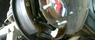
Crankshaft position sensor (CPS)
The Niva DPKV is installed in a special hole in the oil pump drive cover. This sensor is responsible for setting the ignition timing. The sensor takes readings from the crankshaft pulley, which has teeth and in one of the places there is “caries”, that is, several pulley teeth are missing. It is “caries” that the DPKV understands in what position the crankshaft is. The sensor itself resembles an inductive coil, which generates impulses when the crankshaft rotates and transmits them to the computer.
If the sensors fail, the car will not start.
Signs of DPKV malfunction:
Feedback on the E-Gas modification
Car enthusiasts who have already made the adjustment notice that if you move the pedal cover clockwise, the car becomes a little more lively. If you press the pedal like before that the car will explode when it starts moving, you should get used to it and not press the gas so hard. There is no difference when you press the pedal to the ground.
Those who have adjusted E-gas for a quieter ride have found highway driving more comfortable. Now, in order to maintain speed, you need to press the accelerator pedal a little harder, which allows your leg to not be under tension as before.
Other motorists do not believe in the positive effect, saying that it is all self-hypnosis. The operation of the electronic accelerator pedal is based on changing the difference in resistance. And even if you move the cover, when you start the engine, the ECU will still consider it zero and adjust the throttle from that moment on. And if you increase the sector mileage, the error “signal outside the permissible range!” will appear. E-gas!
Have you encountered such a modification of E-gas? What feedback can you give about these adjustments? Is there a positive effect or is everything at the level of self-hypnosis? We remind you that if necessary, you can check the E-gas yourself. By the way, an alternative to modifying the electronic accelerator pedal is chip tuning.
Since 2015, the VAZ-2123 car has been equipped with an electronic engine management system with controller ME17.9.71 2123-1411020-50 according to EURO-5 toxicity standards.
The electronic engine control system (ECM) consists of a controller, sensors for engine parameters and vehicle operating parameters, as well as actuators.
The controller is a special-purpose minicomputer that includes random access memory (RAM), programmable read-only memory (EPROM), and electrically reprogrammable memory (EPROM).
RAM is used by the microprocessor to temporarily store current information about engine operation (measured parameters) and calculated data.
In addition, fault codes that occur are recorded in RAM.
This memory is volatile, meaning that when the power is turned off (by disconnecting the battery or disconnecting the wiring from the controller), its contents are erased.
The EPROM stores the engine control program, which contains a sequence of operating instructions (algorithms) and calibration data (settings).
The EPROM determines the most important parameters of engine operation: the nature of the change in torque and power, fuel consumption, ignition timing, exhaust gas composition, etc. EPROM is non-volatile, meaning the contents of its memory do not change when the power is turned off.
The EEPROM stores controller, engine and vehicle IDs.
Record operating parameters, as well as violations of engine and vehicle operating modes. This is non-volatile memory.
The controller is the central unit of the engine control system. It receives information from sensors and controls actuators to ensure optimal engine operation at a given vehicle performance level.
The controller is located in the passenger's foot area and is attached to the bulkhead.
The controller controls actuators such as the fuel injectors, electric throttle body, ignition coil, oxygen sensor heater, canister purge valve and various relays.
The controller controls the switching on and off of the main relay (ignition relay), through which supply voltage from the battery is supplied to the system elements (except for the electric fuel pump, electric fan, control unit and APS status indicator).
The controller turns on the main relay when the ignition is turned on. When the ignition is turned off, the controller delays turning off the main relay for the time necessary to prepare for the next ignition (completion of calculations, setting the throttle valve to the position before starting the engine).
When a contact is inserted, the controller, in addition to performing the above functions, exchanges information with the APS (if the immobilization function is enabled). If, after the exchange, it is determined that access to the vehicle is permitted, the controller continues to perform engine control functions. Otherwise, engine operation will be blocked.
The controller also performs a system diagnostic function.
It detects the presence of malfunctions in system elements, turns on the alarm and remembers codes that indicate the nature of the malfunction and help the mechanic make repairs.
The engine management system uses a mass air flow sensor with a hot-wire anemometer with a frequency response digital output signal.
It is located between the air filter and the suction pipe.
The mass air flow sensor signal is a frequency signal (Hz), the pulse repetition rate of which depends on the amount of air passing through the sensor (it increases with increasing air flow). The diagnostic tool reads the sensor readings as air flow in kilograms per hour.
Throttle Position Sensors (TPS)
The EDS system uses two TPS. TPS are part of the electrically actuated throttle valve.
DPDZ is a potentiometric type resistor, one of the terminals of which is supplied with a reference voltage (5 V) from the controller, and the other “ground” is supplied from the controller.
From the output connected to the moving contact of the potentiometer, the TPS output signal is supplied to the controller.
The controller electrically controls the throttle position based on the accelerator pedal position.
Based on the accident data, the controller controls the throttle position.
When the ignition is turned on, the controller sets the damper to the pre-start position, the degree of opening of which depends on the coolant temperature.
In the pre-throttle position, the TPS 1 output should be within 0.65. 0.79V, TPS 2 output is within 4.21. 4.35 V.
If the engine does not start and the accelerator pedal is depressed for 15 seconds, the controller disables the throttle actuator and the throttle valve is set to the 7-8 throttle opening position.
In the de-energized state (LIMP HOME) of the electric throttle actuator, the TPS 1 output signal is within 0.80. 0.85V, TPS 2 output is within 4.15. 4.20 V.
Additionally, if no action is taken within 15 seconds, throttle position control mode 0 ("learn") will occur - the throttle valve will fully close and open to the pre-start position, and then the electric throttle will return to the pre-start position. De-energized mode.
At any throttle position, the sum of the TPS 1 and TPS 2 signals should be (5 ± 0.1) V.
In the event of a malfunction in the TPS circuits, the controller de-energizes the throttle valve actuator, stores its code and activates the indicator. In this case, the throttle valve is set to the throttle valve opening position 7-8.
Vehicles with an electronic throttle control unit use an electronic throttle pedal that electrically transmits the accelerator pedal position signal to the controller.
The electronic accelerator pedal is located on a bracket under the driver's right foot.
The electronic accelerator pedal uses two accelerator pedal position (ACP) sensors. DPPAs are potentiometric resistors that are powered by the 5V controller.
The DPPAs are mechanically linked to the transmission by a pedal lever. Two independent springs between the pedal arm and the housing provide return force.
Receiving an analog electrical signal from the EPA, the controller generates a signal to control the throttle position.
The output voltage of the DPPA varies in proportion to the pressure on the accelerator pedal.
When the accelerator pedal is released, the DPPA 1 signal should be within 0.46... 0.76 V, the DPPA 2 signal should be 0.23... 0.38 V.
With the accelerator pedal fully depressed, the DPPA 1 signal should be in the range of 2.80... 3.10 V, the DPPA 2 signal should be in the range of 1.40... 1.55 V.
At any accelerator pedal position, the DPPA 1 signal should be twice the DPPA 2 signal.
Coolant temperature sensor (DTOZH)
The sensor is installed in the engine coolant flow, on the outlet pipe of the engine water jacket.
The sensitive element of the coolant temperature sensor is a thermistor, which is a resistor whose electrical resistance changes with temperature.
High temperature causes low resistance and low coolant temperature causes high resistance. The controller supplies 5V voltage to the coolant temperature sensor circuit.
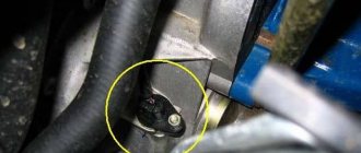
The knock sensor (DS) is installed on the cylinder block (Fig. 10).
The piezoceramic DD sensor generates an alternating voltage signal, the amplitude and frequency of which correspond to the vibration parameters of the motor.
When beating occurs, the amplitude of vibration of a certain frequency increases.
At the same time, the controller adjusts the ignition timing to extinguish the shot.
Checking the oxygen sensor (UDC)
The most effective reduction in the toxicity of exhaust gases from gasoline engines is achieved with a mass ratio of air and fuel in the mixture (14.5.14.6): 1.
This ratio is called stoichiometric.
With this composition of the air-fuel mixture, the catalytic converter more effectively reduces the amount of hydrocarbons, carbon monoxide and nitrogen oxides released in the exhaust gases.
To optimize the composition of the exhaust gases in order to obtain maximum efficiency of the catalytic converter, a closed-loop fuel control system is used with feedback on the presence of oxygen in the exhaust gases.
Diagnostic oxygen sensor (DDC)
A catalytic converter is used to reduce hydrocarbons, carbon monoxide and nitrogen oxides in exhaust gases.
The neutralizer oxidizes hydrocarbons and carbon monoxide, causing them to turn into water vapor and carbon dioxide.
The neutralizer also extracts nitrogen from nitrogen oxides.
The controller controls the redox properties of the converter by analyzing the signal from a diagnostic oxygen sensor installed after the converter.
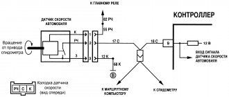
The vehicle speed sensor emits a pulse signal that tells the controller the speed of the vehicle. The DSA is mounted on the distributor input shaft.
When the drive wheels turn, the DSA generates 6 pulses per meter of vehicle movement.
The controller determines the vehicle speed based on the pulse repetition rate.
The crankshaft position sensor is mounted on the camshaft cover approximately 1 ± 0.4 mm from the top of the transmission gear teeth attached to the crankshaft.
The drive disc is integrated with the generator drive pulley and is a gear with 58 teeth spaced at 6° pitches and a "long" timing cavity formed by the two missing teeth.
When the first half of the toothed sector of the disk after the “long” cavity is aligned with the DPKV axis, the crankshaft is in position 114 ° (19 teeth) at the top dead center of the 1st and 4th cylinders.
When the main disk rotates, the magnetic flux in the sensor's magnetic circuit changes, causing alternating voltage pulses in its winding.
The controller determines the position and speed of the crankshaft from the number and repetition rate of these pulses and calculates the phase and duration of the control pulses for the injector and ignition coil.
The phase sensor is installed on the upper tide.
The operating principle of the sensor is based on the Hall effect.
There is a special pin on the engine camshaft.
When the pin passes over the end of the sensor, the sensor emits a low voltage pulse (approximately 0 V) to the controller, which corresponds to the position of the piston of the 1st cylinder on the compression stroke.
The phase sensor signal is used by the controller to organize sequential fuel injection depending on the order of the engine cylinders.
The brake light switch is part of the brake pedal assembly and is designed to provide appropriate signals to the ECM when the driver presses/releases the brake pedal.
In wire-by-wire (E-Gas) systems, the brake pedal switch signals are important because they are used by the safety function of the ECM software.
For this reason, it is very important to ensure that the brake light switch is always in working order.
If its functional switching characteristics do not correspond, for example, if the adjustment values specified in the instructions spontaneously change (due to vibration of the brake pedal, wear of the switch and pedal lock), the car’s engine may enter an emergency situation with a forced reduction in power.
The clutch pedal position switch is part of the clutch pedal assembly and signals to the ECM that the clutch pedal is depressed.
The switch has a set of contacts that switch the voltage from terminal “15” of the ignition switch.
When the clutch pedal is depressed, the contacts are open.
The clutch pedal position switch signal is used by the ECM software to improve vehicle handling.
Throttle Position Sensor (TPS)
The TPS is installed on the throttle itself and is a potentiometer. This sensor reads readings from the throttle position and transmits them to the ECU. The damper opens access to air, thereby increasing engine speed. When the damper opens, the sensor sends a signal to the control unit to increase the fuel supply, which is necessary to form a working air-fuel mixture.
The sensor that most often fails is an unreliable element of the system. Subsequently, they abandoned it and switched to an electronic throttle.
Signs of a malfunction of the TPS:
- High speed at start-up;
- Jumps in engine speed;
- Increased fuel consumption;
- Not smooth idle;
Flaws
Reflashing the program allows you to increase the power of the Chevrolet Niva engine. But there are some disadvantages to this process:
a specialist will charge a lot of money for such work;
there is always a risk that the ECU will fail;
after performing aggressive firmware, which is performed to increase engine power, the assigned resource is often reduced by up to five percent. At the same time, fuel consumption indicators increase;
Serious errors may appear in the system.
The opinions of experts regarding the advisability of performing chip tuning are different. Some people think that performing such work will only benefit the car. The engine will be able to show maximum capabilities without harming the system itself.
According to other professionals, such work will reduce the performance parameters of the machine and lead to a decrease in the service life of the vehicle.
You can tune the engine only after a serious analysis has been carried out and all functional features have been carefully considered. The use of flashing can be called a method alternative to mechanical modification.
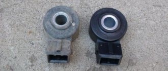
Knock sensor(DD)
The knock sensor is installed on the right side of the vehicle's cylinder block. A DD is needed to catch detonations in the engine and adjust the fuel mixture. The sensor itself is made on the principle of a piezoelectric element and, in the presence of vibrations in the engine, transmits impulses to the ECU, which in turn adjusts the fuel mixture.
Signs of DD malfunction:
- Increased fuel consumption;
- Uneven operation at idle (increased vibrations);
- Jerks when the car moves;
DMRV service life
The service life of the mass air flow sensor directly depends on the purity of the air passing through it. The probable cause of flow meter failure as a result of contamination of the heating elements of the flow meter can be identified by removing the sensor and visually inspecting their condition. Deposits on working surfaces will indicate the need to replace the unit or attempt to clean the deposit.
You can extend the service life of the mass air flow sensor by independently monitoring the condition of the engine air filter element and promptly replacing it with a new one. For very dusty Russian roads, which is observed in most regions, the filter may need to be replaced several times in one year or every five to six thousand kilometers. At the same time, the official maintenance regulations for most cars specify a replacement interval no more often than a visit to the next maintenance. Depending on the production, the vehicle service interval can be 10,000 km or 15,000 km.
Oil pressure sensor (OPS)
The oil pressure sensor is located on the right side of the cylinder block and is screwed into the oil line fitting. This sensor is necessary to monitor the oil pressure in the engine. As you know, operating a car with low oil pressure in the internal combustion engine can damage it. When the oil pressure in the internal combustion engine decreases, the sensor closes the contact and sends a signal to the Niva instrument panel, lighting up the oil pressure indicator in the form of a red oil can.
Signs of DDM malfunction:
Reviews from “traditional craftsmen”
Do-it-yourselfers who have experience doing Chevrolet Niva chip tuning with their own hands often say that such work did not make sense. They claim that the engine is capable of adapting to existing conditions, “self-learning.” Indeed, this is typical for Bosch ECU models 7.9.0 and M 7.9.7, as well as M 7.9.7+. But if the “January” block of model 7.2 is installed in the engine, it is quite advisable to perform a flashing, changing all the factory settings. Then the engine power indicators can increase up to 10%. It is advisable to entrust such work to a specialist. The final quality directly depends on this. This way you can avoid negative consequences.
Idle air control (IAC)
This sensor is located, just like the TPS, on the Niva’s throttle valve. The essence of the sensor's operation is to open and close the channels through which air flows to operate at idle speed. The IAC is involved in the operation of the internal combustion engine only at idle; when the speed increases, the regulator is switched off. IAC is a kind of DC motor with worm gear. Quite often the sensor fails. Subsequently, this sensor was abandoned in favor of an electronic throttle.
Adjusting old-style E-gas
The block cover (11183-1108500) is fixed with bolts that are inserted into oval holes. The improvement is this. to loosen the 4 screws and turn the cover in the desired direction:
- Economy mode (counterclockwise). To drive smoothly, to accelerate, you should press the pedal a little more than before. Gasoline consumption is reduced;
- Active mode (clockwise). The car reacts even with slight pressure on the gas pedal. Gasoline consumption increases. The pedal becomes more sensitive and informative.
In other words, we get the same effect as after installing JETTER (Jetter or spur).
It has been noticed that the first minutes after such settings, the idle speed may be increased (about 1300 rpm). But after a minute, the ECU gradually adjusted and the speed dropped to the usual level. If this does not happen, turn on the ignition for a minute and then start the engine.
If necessary, you can easily return to the original position (mark it in advance).
Brake pedal sensor
The brake pedal sensor is installed on the pedal assembly under the Niva's steering column. In cars without the E-GAZ system, it is only responsible for turning the brake lights on and off. In cars that have an electronic throttle and therefore an electronic gas pedal, this sensor affects the operation of the pedal. If the brake sensor breaks down, the gas pedal stops working.
Signs of malfunction:
- The gas pedal does not work;
- Jerking when moving at a constant speed;
- Loss of power and vehicle dynamics;
The design and principle of operation of the electronic gas pedal
To understand how it works and functions, you need to roughly understand the general circuit of the mechanical analogue. The functions of these systems are similar, but the simplest unit can only be considered a traditional drive.
The gas pedal is a control element for the throttle and its damper. The function of the throttle is to regulate the amount of air. The more air, the higher the engine speed the crankshaft will rotate. The pedal is connected to the throttle drive via a cable drive or levers. All this significantly reduces the effort required to press the gas.
The operating principle of the electronic unit is more complex, but this makes the process of controlling speed easier. The electronic accelerator is used only on engines with an injection power system. Its device is completely electronic. It is based on electronic modules that convert electrical signals.
Structurally, the unit consists of a plastic lever and a mounting bracket - there are two sensors inside the bracket. All these elements form a single, non-separable structure.
Potentiometers are used as sensors. The movable contact of which is in rigid connection with the axis of the plastic pedal lever.
When the driver presses the accelerator, the electronics sends information about the position of the lever to the unit responsible for converting signals. In the next step, the signal is amplified and the throttle is opened according to the vehicle settings.
If we consider the classic scheme, the pedal axis is aligned with the potentiometer slider. The variable resistor is manufactured on a printed circuit board using sputtering technology. When you press the accelerator, the potentiometer sliders move along the sprayed surface, changing the resistance in the circuit.
New car models use two potentiometers. This approach increases the reliability and accuracy of control. If one resistor fails, the system will use the readings of the second.
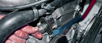
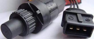
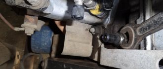
Speed sensor (DS)
The speed sensor of the Niva car is installed in the transfer case. The function of the sensor is to transmit vehicle speed readings. The sensor also forms the fuel mixture; when the car is moving at neutral speed, you can notice that the speed is slightly higher than when the car is running at XX while standing still. Increased speed when driving is necessary to avoid dips when turning on the speed and sharp acceleration.
Signs of DS malfunction:
- Increased fuel consumption;
- There are no increased speeds when driving at neutral speed;
- Dips during acceleration;
- The speedometer does not work;
Repair
If there are any problems with the pedal, then only a complete replacement of the unit will help. But before changing anything, it is worth identifying the cause of the malfunction. To do this, you can use a multimeter test.
You can disconnect the sensors and the block and remove the pedal. Check the resistance - when you press the gas it should change slowly. Jumps in indicators indicate malfunctions.
But sometimes repairs are possible - for example, the wiring is damaged. If a wiring defect is detected, you can use the following diagram.
- Release the axis on which the gear is attached.
- Remove the wiring harness.
- Then the wires are soldered off.
- Release the bracket and pull out the cable.
Next, change the wires and solder them according to the connector under the pedal.
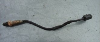
Oxygen sensor (DC, lambda probe)
An oxygen sensor, also known as a lambda probe, is installed in the exhaust system of a car. In some versions of cars, two sensors are installed before the catalyst and after the catalyst. Two sensors are installed in Niva with EURO-4 standards. The sensor captures exhaust gases and transmits readings to the ECU. If there is a large amount of unburned gasoline in the exhaust gases or, on the contrary, a small amount, then the DC makes changes to adjust the fuel mixture.
Signs of DC malfunction:
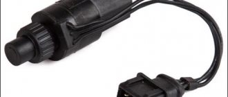
Ignition module (IZ)
The ignition module is installed on the left side of the engine on a bracket. This sensor is involved in the formation of ignition. It is this that produces the high-voltage voltage necessary to create a spark in the combustion chamber of the internal combustion engine. The module has two coils, they are also autotransformers, which produce a spark in pairs, each coil for two cylinders. If one of the coils fails, two cylinders fail at once.
Source