A vehicle speed sensor (VS) is necessary to measure the speed of a vehicle. The readings from the sensor are transmitted to the electronic control unit (ECU), which controls the engine and adjusts engine operation. On the vast majority of cars, the speed sensor is located directly on the gearbox, closer to the speedometer drive mechanism.
Among the main malfunctions of the DSA are: open circuits, damage or oxidation of contacts, failure of the sensor itself, malfunction of the speed sensor drive. If malfunctions occur, the speed sensor is checked with and without dismantling:
- multimeter (measuring signals within the operating cycle);
- using a control lamp;
Detailed information about the signs of a malfunctioning speed sensor, as well as how to check it, is presented in our article.
Inductive speed sensors
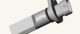
Rice. Inductive speed sensor (design):
- Permanent magnet
- Sensor housing
- Motor housing
- Pole contact pin
- Winding
- Air gap
- Gear wheel with reference point
Design and principle of operation The sensor is mounted directly opposite the ferromagnetic gear (item 7) with a certain air gap. It has a soft magnetic steel core (pole contact pin, item 4) with a winding (5). The pole contact pin is connected to a permanent magnet (1). The magnetic field propagates through the pole contact pin, passing into the gear. The magnetic flux passing through the coil depends on whether the location of the sensor falls opposite a wheel cavity or tooth. The tooth connects the magnetic leakage flux emanating from the magnet into a beam. The network flow is enhanced through the coil. The depression, on the contrary, weakens the magnetic flux. These changes in magnetic flux as the gear rotates induce a sinusoidal output voltage in the coil that is proportional to the rate of change and the engine speed. The amplitude of the alternating voltage increases rapidly with increasing speed (several mV... > 100 V). Sufficient amplitude is present starting from a minimum speed of 30 per minute.
Rice. Inductive engine speed sensor signal:
Typical failures of an analog speedometer
- Breakage of the flexible shaft. The reason is the natural aging of the metal or mechanical impact on the casing, as a result of which the shell and cable rub against the car body and parts of attachments.
- Breakage of the worm gear that transmits rotation of the gearbox secondary shaft to the cable. Often the flexible shaft drive is made of plastic, which is why, at long runs, the gear teeth are licked off and the cable seat in the housing is damaged. Less common is a breakdown of the drive drive inside the gearbox, due to which the rotation of the secondary shaft is not transmitted to the cable.
- There is a malfunction in the speed display mechanism inside the dashboard.
- Extraneous sound when accelerating. The reason is a frayed cable or improper installation of the flexible shaft, which causes the cable to exert increased resistance on the casing when rotating.
Differential Hall sensor
On a current-conducting plate through which magnetic induction B passes vertically, a voltage UH (Hall voltage) proportional to the direction of the current can be removed transverse to the direction of the current.
Rice. Operating principle of a differential Hall sensor:
- a Sensor location
- b Hall sensor signal
- large amplitude with small air gap
- small amplitude with large air gap
- with Output signal
- Magnet
- Hall sensor 1
- Hall sensor 2
- Gear
In a differential Hall sensor, the magnetic field is generated by a permanent magnet (item 1). Between the magnet and the pulse ring (4) there are two Hall sensor elements (2 and 3). The magnetic flux that passes through them depends on whether the speed sensor is located opposite a tooth or a slot. By creating a difference in the signals from both sensors, a reduction in magnetic disturbance signals and an improved signal-to-noise ratio are achieved. The side surfaces of the sensor signal can be processed directly in the control unit without digitization.
Instead of a ferromagnetic gear, multi-pole gears are also used. Here, a magnetizable plastic is mounted on a non-magnetic metal carrier, which is alternately magnetized. These north and south poles take on the function of the teeth of the wheel.
AMR sensors
Rice. Principle of determining the speed using the AMP sensor:
- a Placement
- at different times
- b AMP sensor signal
- with Output signal
- Pulse (active) wheel
- Touch element
- Magnet
The electrical resistance of a magnetoresistive material (AMP, anisotropic magnetoresistive) is anisotropic. This means that it depends on the direction of the magnetic field that affects it. This property is used in the AMP sensor. The sensor is located between the magnet and the pulse ring. The field lines change their direction when the impulse (active) wheel rotates. The result is a sinusoidal voltage, which is amplified in the data processing circuit and converted into a square wave signal.
GMR sensors
The improvement of active rotation speed sensors is reflected in the use of GMR (Giant Magneto-Resistance) technology. Due to the high sensitivity compared to AMP sensors, larger air gaps are possible, making them suitable for difficult applications. Higher sensitivity produces less signal edge noise.
All two-wire ports previously used in Hall speed sensors are also possible in GMR sensors.
In some cases, it is necessary to check the performance of various automotive sensors. For example, if the car stalls at idle, then it is necessary to diagnose the sensors, check for serviceability of the mass air flow sensor, air sensing sensor, variable speed sensor, and DPKV. In this useful information we will look at how to check the speed sensor with your own hands.
The speedometer on my car stopped working
Cars are equipped with analogue, electronic speedometers with a mechanical drive and fully electronic speed meters. Each type of device is characterized by its own malfunctions and symptoms of their manifestation. Let's look at how a car speedometer works, common breakdowns, and reasons for the failure of the speed sensor and indicator inside the dashboard.
How the car speed sensor works
Although this device does not mechanically affect the movement of internal combustion engine parts in any way, it performs a useful function, namely, the speed sensor transmits data with errors that adversely affect the quality of engine operation. The speed meter transmits signals to the sensor that controls the overall operation of the internal combustion engine at idle speed, and also, using the IAC (idle speed controller), regulates the air flow that bypasses the throttle valve. The faster the car's wheels spin, the more signals are transmitted.
The speed sensor device operates on the basis of a Hall sensor. During engine operation, the DS sends pulse-frequency signals to the electronic control unit (ECU) at certain short intervals. For one kilometer of distance traveled by a car, the speed sensor sends about 6 thousand signals to the ECU. Using the signals received from the DS, the ECU determines at what speed the car is moving.
What is the Hall effect? The Hall effect is when you place a conductor carrying a constant current in a magnetic field, an electric voltage appears.
In designs of various brands and models of cars, the speed sensor is installed both next to the speedometer and next to the gearbox. But did you know that there is such an incoming air temperature sensor, based on the readings of which the on-board computer decides how much fuel and air to supply. Therefore, the role of this sensor is not as simple as it seems. If the intake air sensor underestimates the temperature, then the mixture is supplied “rich”, which leads to flooding of the spark plugs.
How does an analog speedometer work?
The drive of the analog speedometer in the dashboard is realized through a flexible cable from the secondary shaft of the manual transmission. The cable is engaged with the shaft through a worm gearbox. There are dial, tape and drum speedometers. The last two design options are already difficult to come across in our time, so let’s consider the design of a dial speed meter.
All analog speedometers of this type of design are designed using the effect of magnetic induction. A unit was built on the basis of a rotating magnet and a card covering the magnet. When the magnet rotates near the aluminum card, eddy currents are induced. The deflection of the needle is proportional to the strength of the eddy currents.
A variation of the design is a speedometer based on a magnet and a metal plate connected to the speedometer needle by a common axis. A flexible cable from the manual transmission transmits rotation to a magnet, which, through the phenomenon of magnetic induction, when moving, carries along a ferromagnetic plate. When the vehicle speed decreases, the arrow returns to its original position due to the return spring.
The odometer drive, which measures the distance traveled, is implemented using the same flexible cable. Inside the speedometer, using a worm gear, the rotation of the cable is transformed into the movement of sections of the distance traveled.
Faulty Speed Sensor: Symptoms and Signs
The DS does not work if the following symptoms and signs appear:
- Idle speed is unstable.
- The speedometer does not work at all or works with errors.
- Fuel consumption is higher than expected.
- The viscosity of the engine has decreased (it doesn’t go uphill like before, it’s also hard to go with a trailer).
- If there is an on-board computer (BC), it may signal that it is not receiving data from the vehicle speed sensor (VS).
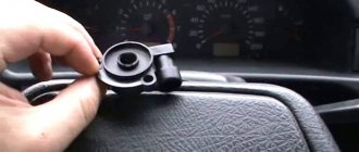
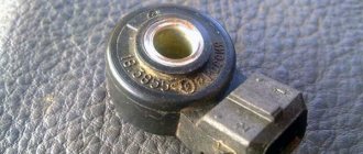
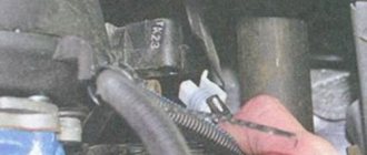
And here's what the speed sensor looks likeAnd here's where the speed sensor is located
Typically, problems with a car speed sensor occur as a result of a circuit break. Therefore, if signs and symptoms are detected, a diagnosis should be made for an open circuit.
First, disconnect the power wires, then inspect the contacts. If the contacts are oxidized, they need to be cleaned and lubricated, for example, with Litol 24. The circuit often breaks near the plug.
If all the wires are intact, then we measure the resistance in the grounding circuit. A working vehicle speed sensor should show a resistance of 1 ohm.
After carrying out minor repair work with your own hands, you need to check whether the DS is working. In the design of the VAZ family of cars and other popular cars, a speed sensor is installed that works like a Hall sensor, that is, it transmits 6 pulses per revolution. There are induction and reed type speed sensors.
Types of speed sensors:
- on the Hall effect;
- inductive speed sensor;
- reed car speed sensor.
The sensor, operating on the principle of a Hall sensor, has 3 contacts: ground, voltage and pulse signal.
What does the speed sensor affect?
Now that the design and principles of operation of speed detectors are covered in detail, it would not be amiss to answer a frequently asked question, namely, “What does the speed sensor affect?” To answer this, first of all, it is worth considering the main purpose of this device. Today it has several purposes, or rather 2 main ones:
- The first is, of course, informing the driver about the speed of the vehicle so that he can fully comply with traffic rules. Here, perhaps, no explanation is required;
- The second is also informing, but not the driver, but other components of the car about the current speed of the car. This information is most important for the fuel distribution units of the machine: injector, carburetor or LPG reducer. It is based on the indicators of the speed sensor that the electronics of these parts organize the operation of the motor at idle or when it moves by inertia. From this we can draw a completely logical conclusion - the correct operation of the engine depends on the serviceability of the speed identifier. That is, if there is excessive fuel consumption, it may well be due to a malfunction of the speed sensor. This is a strange reason for a problem known to many, but when it appears, many motorists begin to check injectors, carburetors or other fuel components, completely forgetting about the device being considered today.
Answering the question about what the speed sensor affects, you can give two completely accurate answers:
- On road safety;
- For correct and stable operation of the vehicle.
Knowing this, probably every driver will stop being dismissive of situations when the speed sensor is faulty, and will try to take appropriate measures in a timely manner.
How to check DS?
First, we check for the presence of grounding and 12 V voltage in the contacts. Such contacts are checked by dialing. And the contact of the pulse signals is checked during torsion.
The voltage between the output and the ground of the working speed sensor ranges from 0.5 V to 10 V.
There are several ways to check your car's speed sensor:
- No. 1 Using a voltmeter.
- No. 2 Without removing the sensor from the car.
- No. 3 Using a light bulb or control.
Checking with a voltmeter:
- Remove the sensor.
- Connect one contact to the pulse signal terminal. We connect the second contact to the ground of the car.
- Next, we turn the speed sensor and see if signals are sent when the cycle is running and measure the output voltage of the DC. To rotate the sensor axis with your own hands, you need to put a tube on the sensor axis and twist it at a speed of up to 5 km/h. The faster you rotate the sensor axis, the more voltage the voltmeter will show.
Without removing the sensor from the car
- We put the car on a jack (jack up one wheel).
- We connect a voltmeter to the contacts of the car speed sensor.
- Spin the raised wheel and see if tension appears. A working sensor should show voltage and frequency (Hertz).
Using a light bulb or control
- Disconnect the pulse data wire from the sensor.
- We jack up one wheel.
- Turn on the ignition and look for “+” and “-“ using the control.
- Use the control to connect the “Signal” wire and turn the wheel by hand. If the sensor is working properly, the control should show a “-” (minus) signal.
Diagnostics
Troubleshooting begins by disconnecting the wiring block from the speed sensor harness and checking them using a test light.
To make a control light bulb, you need any car lamp that can operate at a voltage of 12 V, and two wires about 1 meter long each. One of the wires is attached to the positive terminal, the second - to the negative terminal of the lamp. The resulting device also includes a Krona battery.
To carry out the test, one wire of the warning lamp is attached to the ground of the body or battery, and the second is made with short, frequent touches to the middle contact of the DC connector. If there are no faults in the connector-speedometer section, the speedometer needle will slightly tremble or rise. If the needle shakes, the answer to the question why the speedometer does not work can be considered found - the speed sensor requires replacement.
In cases where the needle’s response to tapping on the central contact of the block cannot be detected, it is necessary to “test” the speedometer power circuit. The procedure is carried out using a multimeter (multitester), or by using the same light bulb - a control.
If the tester in the “continuity” mode indicates a violation of the integrity of the circuit, further troubleshooting is carried out in this direction. It is necessary to check the fuses, the connection points of the wires, and their integrity inside the insulating braid.
How to check induction DC?
The voltage of such a sensor varies with wheel speed, as with the steering angle sensor. From the rotation of the wheels, the signal begins to be transmitted, so this operating principle is similar to oscillations of a wave pulse.
All modern cars are equipped with a speed sensor. Its task is to measure speed and transmit the received information to the electronic control unit. Thanks to the signals received from the sensor, parameters that affect engine operation are adjusted (amount of air supplied, idle speed, etc.) The higher the speed, the higher the frequency of the signals.
Symptoms of a problem
If the DS fails, the electronics will immediately notice this; the matter will not be limited to the absence of readings on the instrument panel. An error will be displayed with the corresponding code, the unit will go into emergency mode, which will immediately affect operation.
The engine will begin to stall in neutral while driving, consumption will increase and power will decrease. The electric power steering, which uses speed information, will fail. The on-board trip computer will stop working.
Design and principle of operation
The DS device is based on the Hall effect; the device transmits pulse-frequency signals to the ECU at certain intervals. So, over one kilometer of travel, this device transmits about 6,000 signals and, based on the data received, the control unit automatically calculates the speed of the vehicle. The higher the speed of the car, the more intense the pulses arrive at the controller. In addition to determining speed, this device performs another important function. When the car is coasting, the pulse sensor does not block the flow of fuel, thereby contributing to savings. The principle of operation of the DS is quite simple, but if any malfunctions occur, this affects the operation of the power unit.
Today it is customary to distinguish several types of DSAs, differing in design: inductive, reed and based on the Hall effect (electronic sensors).
Main causes of malfunction
A speed sensor breakdown should be repaired in a timely manner before it develops into an expensive repair. To do this, every car owner must monitor how his vehicle behaves while driving. At the slightest deviation from the established norm, it is recommended to replace the DSA. The main symptoms of a speed sensor malfunction:
- fuel consumption increases;
- incorrect speedometer readings;
- the engine is unstable at idle;
- the motor does not develop full power.
Also, signs of speed sensor failure may appear in situations where the engine stops working at idle, while squeezing the clutch, or while shifting gears. In this case, the driver will see an indicator with the words “Check engine”; if there is a computer, the display will show error “24”. In this situation, the first step is to check the condition of the contacts and wires; perhaps an open circuit will be detected. As a rule, this occurs near the connector where there is a bend, and the wires can fray. If the contacts are simply dirty or oxidized, they need to be cleaned. You also need to monitor the integrity of the wire insulation at the exhaust manifold. A sensor malfunction may be caused by a failure of the speedometer cable, which has become worn out during operation.
Let's sum it up
The speed sensor (speedometer sensor) is an important element in the electronic engine control system. If the driver notices the signs of engine malfunctions discussed in the article, special attention should be paid to the vehicle speed sensor.
We also recommend reading the article about what a phase sensor is. From this article you will learn about the signs of a faulty phase sensor, as well as how to check it.
In addition to checking other sensors (mass air flow sensor, speed sensor, speed sensor, etc.), it is also necessary to diagnose the speed sensor. The reason is that the failure of one or another sensor will not always be accompanied by the lighting of the “check engine” warning light on the instrument panel. As a result, in-depth diagnostics are required.
Self-test
Every car owner should know how to check the speed sensor . There are three possible ways to determine if it is working properly. Before starting diagnostics, you should determine whether the sensor produces 12 V, since the basic principle of operation of the internal combustion engine is based on the Hall effect, the state of the contacts occurs exclusively during rotation. The voltage readings of the sensor in operating condition should be within 0.5-10 V. 1. Check with a voltmeter. The DSA needs to be removed and it will be determined what each terminal is responsible for. One contact of the voltmeter should be connected to the terminal that outputs pulse signals, and the second should be connected to the ground wire. The sensor must be rotated and at this time look at the voltage readings. The more intense the sensor rotates, the higher the readings will be. 2. It is necessary to disconnect the impulse wire, which is detected by a special controller, and lift the wheel to rotate with a jack so that it does not touch the ground. Connect the “Signal” control wire; if the indicator is “-“, then the speed sensor is working. A wire with a light bulb can replace the control in this method. 3. To determine the operation of the sensor, it is not necessary to remove it from the machine; to do this, you can lift it, as in the previous method. Next, connect the voltmeter to the sensor contacts; the device will display voltage readings when the wheel rotates. If the voltmeter shows voltage and frequency in Hz, this indicates that the DS is working.
In modern cars, an electronic control unit and various sensors, including the Toyota speed sensor, are responsible for the injection of the combustible mixture at different engine operating modes. The ECU, analyzing the condition of the car based on many factors, promptly carries out calculations, accurately doses the amount of combustible mixture and determines the time for which the injector of a certain engine cylinder opens at the required moment in time.
The controller must receive information from the vehicle sensors:
- about the speed of movement;
- about the throttle position;
- about the position of the engine crankshaft;
- air and coolant temperature;
- about the presence of detonation and other data.
Purpose
The speed sensor is designed to inform the electronic control unit about the speed of the vehicle. In addition, it is also assigned an information function - speedometer readings on the control panel.
Engine operating modes, which are associated with cutting off the fuel supply in the event of closing the throttle valve when the car is in motion, as well as the smooth transition of the engine to idle mode, depend on engine speed and speed. The control unit, having received the necessary impulses, adjusts or changes the parameters of the engine operating modes. Therefore, when the car is moving at high speed, the idle speed is maintained slightly higher than when driving at low speed or when the car is stationary.
Principle of operation
Speed sensor circuit
Operating principle of the speed sensor
Many car enthusiasts do not know where the speed sensor is located and especially how it works. The Toyota speed sensor is mounted on the gearbox housing.
The operating principle is quite simple and is based on the Hall effect. While the vehicle is moving, voltage pulses are transmitted from the sensor to the electronic control unit, the frequency of which is directly proportional to the speed of rotation of the vehicle's drive wheels. The task of the device is to generate a certain number of frequency pulses per revolution of the car wheel. These pulses are a kind of frequency signal to the controller to carry out the necessary calculations. When designing each car, it is designed for wheels of certain sizes. Therefore, if you install wheels of a different size than those provided by the manufacturer on your car, the speed readings of the car may change slightly.
The speed sensor generates approximately 6004 pulses for each kilometer traveled. The controller determines the speed of the vehicle based on the time intervals between pulses. After calculation, data on driving speed is also displayed on the speedometer in a form convenient for the driver.
Consequences of device failure
The car's electronic system regularly diagnoses all sensors installed on the car, including the speed sensor. The diagnostic system determines the malfunction of any sensor by the absence of a signal from it.
If there is no signal from a faulty motion sensor, the vehicle's electronic control unit cannot determine the state of the vehicle: whether it is moving or standing still. And only when the engine starts to operate at high speeds under increased load and the air consumption increases accordingly, the system determines that the car is in motion. If, under such conditions, there are still no signals (impulses) from the device, then the electronic control unit generates a CHECK ENGINE error.
A malfunction of the speed sensor primarily affects the maintenance and regulation of idle speed while the vehicle is moving. So, if you suddenly release the accelerator pedal or turn off the gearbox (sharp decrease in engine load), the engine may stall. When you press the accelerator sharply, for example for dynamic acceleration, you will notice a significant loss of the engine's dynamic characteristics during acceleration. The engine will stop (stall) when the vehicle is coasting or when changing gears.
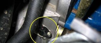
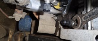
Location of the speed sensor on the automatic transmission
Close-up location of the speed sensor on the automatic transmission
You can check the device in 3 ways, for the first two you need a multimeter.
FIRST METHOD
- the sensor is removed;
- using a multimeter you need to find out what each contact is responsible for, you need to find the pulse one;
- the positive probe is connected to the pulse contact, and the negative probe is connected to the car body or engine;
- A piece of tube is put on the sensor axis and rotates at a low speed, while the voltage is measured with a multimeter: the higher the rotation speed, the higher the pulse frequency and voltage.
SECOND METHOD (WITHOUT DISASSEMBLY)
- use a jack to lift one of the front wheels of the car;
- the multimeter is connected to the sensor wires;
- you need to rotate the wheel and check whether pulses appear (if so, the device is working normally).
THIRD METHOD (WITHOUT MULTIMETER)
If a measuring device is not available, the test can be performed using a test lamp or a regular 12-volt light bulb. The procedure is similar to the second method.
- The pulse wire is disconnected from the sensor;
- with the ignition on, use a control lamp to find “plus” and “minus”;
- the wheel is hung out;
- the control lamp is connected to the signal wire, the wheel rotates (if the “minus” lights up on the control, the sensor is working).
If you don’t have a warning lamp at hand, you can use a 12-volt one (for example, from a turn signal). The wire connects the battery plus and the signal contact. If the sensor is operational, the light will blink.
If the check shows that the device is working properly, you need to check how its drive works. To do this, the front wheel is hung out. You need to find the sensor drive by touch. Then you need to rotate the wheel with your foot, and with your hand you need to check whether there is rotation in the drive and whether it is stable.
Replacing sensors
The cause of failure of speed sensors is a short circuit in the wiring when the wires come into contact with the exhaust manifold, which begin to melt due to high temperature.
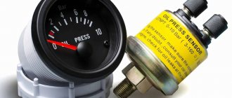
Original sensor
Andrey Goncharov, expert in the “Car Repair” section
How to replace the speed sensor
Replacing the speed sensor is a fairly simple procedure that does not take much time, so many drivers do it themselves. To replace the speed sensor yourself, you must follow the procedure algorithm: The battery must be disconnected from the on-board grid and only after that the DS must be disconnected. In this case, it is recommended to use two keys in work - “10” and “21”. In some cases, you will need keys of a different size, depending on the make of the car. It is necessary to unscrew the sensor itself as carefully as possible (so as not to damage the rod). If it cannot be repaired, you need to purchase an identical one with an equal number of teeth on the gear. Installing a new element occurs in the reverse order. The rod is installed in the sensor sleeve, followed by an O-ring pre-treated with oil, and the speed sensor is fixed in place. After installing the new device, the ECU errors should be reset, otherwise the machine will not consider the sensor replacement effective.
What to pay attention to
Before starting the procedure for replacing the speed sensor, you need to turn off the ignition, since the presence of voltage in the circuit when connecting a voltmeter can lead to a short circuit and failure of other elements. In order to avoid encountering rod defects when removing the speed sensor, it is necessary to dismantle the speedometer drive. To remove it, use a regular wrench. The procedure should be carried out very carefully, removing the drive from the body of the gearbox, and it is important not to lose the rod in the place of the manual transmission.
Replacement instructions
Replacing the sensor is not difficult; it is usually secured in the gearbox housing with a screw to the flange. By unscrewing this screw and removing the connector, the sensor can be removed and a new one installed.
A standard gasket or sealant is used for sealing. After replacement, you need to reset the current errors using a scanner or briefly removing the terminal from the battery.
Before carrying out the operation, you must thoroughly clean the box housing around the sensor to avoid abrasives getting into the crankcase. Adjacent surfaces are wiped free of dirt, oil and oxides.
How to extend the service life of a DS
The design of the DS is not particularly complicated, and almost every car owner can replace it independently. Therefore, many do not pay due attention to this device, which to some extent contributes to its malfunction. Drivers who drive at high speeds are at greater risk, since the installed speed sensor has a plastic shank, which is quickly broken by a cable during strong vibration.
Often the cause of the malfunction can be the cable itself, since it is influenced by factors such as moisture and reagents used to treat roads. This destroys its structure: the cable loses its original elasticity, begins to crack and delaminate. To prevent it from premature rubbing, you need to regularly treat it with any machine oil, pumping it with a syringe under the braid.
Special attention should be paid to the DS shank in the place where the sensor itself and the cable are connected. If the shank is plastic, it becomes loose during the operation of the car, which leads to the fact that its seat becomes broken. This leads to the fact that the DS fails, and the shank cannot be repaired. As a result, you will have to change the entire device. You should also know that the speed sensor contacts need regular cleaning, since exposure to external factors leads to their oxidation. Deterioration of voltage conductivity can lead to a short circuit that will damage the device. Now every car owner can evaluate the value of the speed sensor in the vehicle, which, in addition to determining the speed, also affects the operation of the power unit. Therefore, it is important to promptly detect and eliminate the malfunction, and, if necessary, resort to replacing it. Before installing a part, the above testing methods must be used to determine its functionality.
Repair
Repair of the speed measurement system directly depends on the identified malfunction:
Speed sensor
- Clean from dirt;
- Clean the pad contacts from corrosion and oxides;
- If the above measures do not help, the sensor is replaced.
Wiring
- Check and clean “mass” contacts;
- Solder or secure with twists the places where the wires are broken, due to which the speedometer stopped working;
- Cover areas where the braid is damaged with insulating tape;
- Replace failed fuses;
- Clean the pad contacts from oxides and corrosion.
Speedometer
If the speedometer stops working, it must be replaced. On domestic cars assembled using an electronic type of speed meter, the speedometer changes along with the instrument panel. You can carry out this operation yourself. To do this, you only need a Phillips screwdriver and pliers.
Repairing an old speedometer can be much more expensive than completely replacing the old instrument cluster with a new one.
The speedometer of the VAZ 2114 does not work? A problem that is quite common not only for models of the fourteenth, almost every VAZ model suffers from this problem, from the classics to the new Prior, Kalin, and Grant. In today's article I will tell you about the three main reasons for the VAZ 2114 speedometer malfunction and how to fix them.