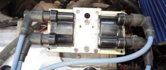
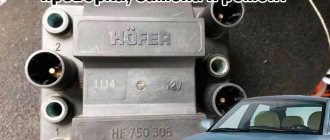
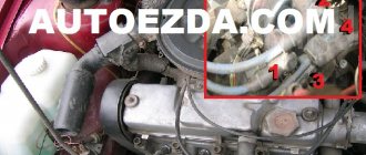
The ignition module exists for injection fields in two modifications. Old sample and new sample. In the old version: a 4-pin connector and a large significant mass were installed on the fields of the first sample. New design: the connector has 3 contacts and low mass.
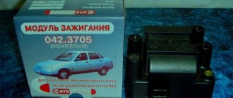
I came across the quality of this standard spare part completely by accident. A client comes for diagnostics and says that in the morning he turns the starter for 5-10 seconds until the engine “cages” for the first time. And at this time the injectors are pouring, it all flies out into the pipe.....and explodes in the muffler, turning around a large can. Having checked the spark as usual for ground, I saw its presence and calmed down. What I didn’t check: the performance of the boosts, replaced the spark plugs and wires, changed the gas station. And in the morning after a winter night we still use the starter to get the oil going. It turned out that the ignition module was to blame. He gave a spark in air to the candles, but its energy was so low that under the pressure in the cylinder, it could not ignite the mixture. On the forums, as usual, we delved into discussions about which modules to buy: Moscow, Stary Oskol or some other ones. I immediately ordered the Bosch module. I won’t delay the story for long....the next morning after installation, the engine started up with half a turn.
I confess that, to my shame, I do not know how the power of a spark is measured and if there are any instruments for this. To measure the power of the ignition module (and not at all for the Niva), I bought an insanely expensive “device” for 5 euros in the Finnish Biltema store, which is a transparent cylinder. This miracle is placed on one of the spark plug wires in an open circuit and in it you can clearly observe the power of the spark live. In the standard version, the gap between the poles is 1 cm, but even this distance may not be penetrated by the module. Subsequently, I made my own device, where the distance between the poles can be changed up to 2 cm and thereby look at the limit and at least the relative characteristics of the work.
Ignition module VAZ 21214 injector connection order
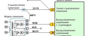
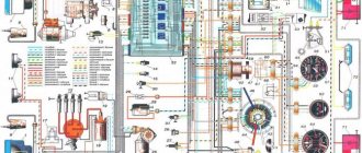
The ignition system (Fig. 1) uses an ignition module consisting of a two-channel electronic switch and two two-terminal ignition coils. The ignition system has no moving parts and therefore requires no maintenance. It also has no adjustments, since the ignition control is completely electronic.
Rice. 1. Ignition system VAZ-21214. 1 - battery, 2 - main relay, 3 - ignition switch, 4 - spark plugs, 5 - ignition module, 6 - controller, 7 - crankshaft position sensor, 8 - drive disk, E - matching devices.
The ignition system uses a spark distribution method called the "idle spark" method. The engine cylinders are combined in pairs 1-4 and 2-3, and sparking occurs simultaneously in two cylinders: in the cylinder in which the compression stroke ends (working spark), and in the cylinder in which the exhaust stroke occurs (idle spark). Due to the constant direction of current in the primary and secondary windings, the sparking current of one spark plug always flows from the central electrode to the side electrode, and the second - from the side to the central one.
Ignition control is carried out by a controller that uses information about the engine operating mode received from sensors of the engine management system.
The ignition system has the following four circuits
Ignition control circuit for cylinders 1 and 4.
The controller generates an ignition control signal to contact “B” of the ignition module. This signal is used to switch the primary winding of the ignition coil and provide high voltage to the spark plugs of cylinders 1-4.
Ignition control circuit for cylinders 2 and 3.
The controller generates an ignition control signal to contact “A” of the ignition module. This signal is used to switch the primary winding of the ignition coil and provide high voltage to the spark plugs of cylinders 2-3.
Ignition module.
The ignition module (Fig. 2) contains two ignition coils and two powerful transistor valves for switching the primary windings of the ignition coils. The controller controls the module by sending signals through the ignition control circuits “1-4” and “2-3”. If any element of the ignition module malfunctions, the entire assembly must be replaced.
| Rice. 2. Ignition module. |
Power circuit.
The car's onboard voltage is supplied from the ignition switch to contact “D” of the ignition module.
Ground circuit.
The ground connection circuit goes from the end of the cylinder head cover to contact “C” of the ignition module.
1. Disconnect the wire from the negative terminal of the battery. 2. Disconnect the wiring harness connector from the ignition module. 3. Disconnect the spark plug wires. 4. Remove the ignition module by unscrewing the fastening nuts.
Installing the ignition module
1. Install the ignition module on the bracket on the engine and secure it with nuts, tightening them to a torque of 3.3. 7.8 N. m. 2. Connect the spark plug wires. 3. Connect the wiring harness. 4. Connect the wire to the negative terminal of the battery.
Scanned and processed by Volodyushka, 01/12/03.
Source
Admiralteyskaya Embankment
Time - 14:25
A walk along the embankment in St. Petersburg is a separate adventure. Here you will see not only a lot of pleasure boats, but also other interesting things. For example, the Kunst Chamber building on the other side, the Palace Bridge, lion figurines on the pier. The Tsar Carpenter monument deserves special mention.
This is another monument to the founder of St. Petersburg, Peter I, who, as you know, was a jack of all trades. A walk along the Admiralteyskaya Embankment ends at the Palace Bridge. We turn right and wait for any bus or trolleybus that will take us to Anichkov Bridge (Liteiny Prospekt stop
Notice
: Undefined variable: text_alt_photo in /var/www/ticketstour.ru/catalog/view/theme/theme_ticketstour/template/product/product_card.tpl
on line
29
English
Bus tour “CITY SIGHTSEEING” around St. Petersburg
Bus sightseeing tour of St. Petersburg on a red double-decker bus using the “hop on - hop off” system
- Saint Isaac's Cathedral
- 1 hour 30 minutes 8,894
from 800
Book
Nearest 06/16/2020 10:00
Notice
: Undefined variable: text_alt_photo in /var/www/ticketstour.ru/catalog/view/theme/theme_ticketstour/template/product/product_card.tpl
on line
29
Sightseeing tour of St. Petersburg
Bus tour of the main attractions of St. Petersburg
- m. Gostiny Dvor
- 1 hour 30 minutes 6,057
from 275
Book
Nearest 06/11/2020 17:45
Notice
: Undefined variable: text_alt_photo in /var/www/ticketstour.ru/catalog/view/theme/theme_ticketstour/template/product/product_card.tpl
on line
29
Sightseeing tour of St. Petersburg with a visit to the Hermitage
Sightseeing bus tour of St. Petersburg with a visit to the State Hermitage Museum
- m. Gostiny Dvor
- 3 hours 5 405
from 500
Book
Nearest 07/02/2020 10:00
Ignition order for Niva 21214 injector
The ignition system (Fig. 1) uses an ignition module consisting of a two-channel electronic switch and two two-terminal ignition coils. The ignition system has no moving parts and therefore requires no maintenance. It also has no adjustments, since the ignition control is completely electronic.
Rice. 1. Ignition system VAZ-21214. 1 - battery, 2 - main relay, 3 - ignition switch, 4 - spark plugs, 5 - ignition module, 6 - controller, 7 - crankshaft position sensor, 8 - drive disk, E - matching devices.
The ignition system uses a spark distribution method called the "idle spark" method. The engine cylinders are combined in pairs 1-4 and 2-3, and sparking occurs simultaneously in two cylinders: in the cylinder in which the compression stroke ends (working spark), and in the cylinder in which the exhaust stroke occurs (idle spark). Due to the constant direction of current in the primary and secondary windings, the sparking current of one spark plug always flows from the central electrode to the side electrode, and the second - from the side to the central one.
Ignition control is carried out by a controller that uses information about the engine operating mode received from sensors of the engine management system.
The ignition system has the following four circuits
Ignition control circuit for cylinders 1 and 4.
The controller generates an ignition control signal to contact “B” of the ignition module. This signal is used to switch the primary winding of the ignition coil and provide high voltage to the spark plugs of cylinders 1-4.
Ignition control circuit for cylinders 2 and 3.
The controller generates an ignition control signal to contact “A” of the ignition module. This signal is used to switch the primary winding of the ignition coil and provide high voltage to the spark plugs of cylinders 2-3.
Ignition module.
The ignition module (Fig. 2) contains two ignition coils and two powerful transistor valves for switching the primary windings of the ignition coils. The controller controls the module by sending signals through the ignition control circuits “1-4” and “2-3”. If any element of the ignition module malfunctions, the entire assembly must be replaced.
Power circuit.
The car's onboard voltage is supplied from the ignition switch to contact “D” of the ignition module.
Ground circuit.
The ground connection circuit goes from the end of the cylinder head cover to contact “C” of the ignition module.
1. Disconnect the wire from the negative terminal of the battery. 2. Disconnect the wiring harness connector from the ignition module. 3. Disconnect the spark plug wires. 4. Remove the ignition module by unscrewing the fastening nuts.
Installing the ignition module
1. Install the ignition module on the bracket on the engine and secure it with nuts, tightening them to a torque of 3.3. 7.8 N. m. 2. Connect the spark plug wires. 3. Connect the wiring harness. 4. Connect the wire to the negative terminal of the battery.
To generate a spark in Niva cars, an ignition module is used. Older Nivas were equipped with a distributor; this part did not inspire reliability and required special attention and frequent revision. With the transition of Niva to injection engines, the need for a distributor disappeared, and it was replaced by a more reliable ignition module.
In this article we will talk about the ignition module of a Niva car, namely how to check it, signs of malfunction and much more. After studying this article, you can easily find a breakdown in your car related to the MH.
Build process
- The front cylinder head cover is installed and a layer of sealant is applied.
- The bolts are tightened.
- The air filter is installed, sealant is applied and the pan is screwed on.
The fitting is unscrewed to bleed air from the block before filling with coolant. Pour liquid into the radiator. After it leaks out of the fitting, the lamb is screwed into place. Filling the engine oil. The hose and crankcase ventilation tube are connected to the fittings, and the copper wires are connected to the ignition coils.
The tips of the high-voltage wires are connected to the spark plugs. It is possible that after unscrewing the spark plugs, the remaining water in the wells penetrates the cylinders. Using a long knitting needle and a clean rag, it is easy to remove moisture from them.
Important! Adjusting the chain improves timing mechanism retention and pulley operation. It is important to ensure regular monitoring of its location.
Purpose and design of the part
The purpose of this sensor is one thing - to supply a reliable spark to the combustion chamber of the car through high-voltage wires and a spark plug. To be more precise, the ignition module does not supply a spark, but only the voltage necessary to form a spark on the spark plug.
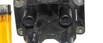
The design of the part is made of heat-resistant plastic, in which two coils are placed. Each of the coils is responsible for the operation of two cylinders. The coils have a primary and secondary winding in which high voltage is generated.
Symptoms of a problem
It is extremely rare for two built-in coils to fail at once, so it is more likely to be possible to start the engine with a faulty unit. However, even an inexperienced driver will immediately suspect something is wrong. The malfunction will appear as follows:
- unstable (floating) idle speed;
- the engine has difficulty picking up speed;
- characteristic sound of the engine (triple);
- jerking when accelerating (while moving).
Operating a car with such a breakdown is possible (you can drive to a garage or car service station), but it is not advisable unless absolutely necessary.
Similar signs of unstable engine operation are possible with a number of other ignition or fuel supply faults. To differentiate possible breakdowns, the performance of the ignition unit should be determined. It would be useful to check the contacts of the wires coming to the device, as well as their integrity.
Examination
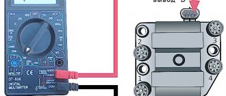
The module can be checked using a special diagnostic tool ELM327 or using a multimeter. Since not every car enthusiast has a diagnostic device, it would be most correct to talk about checking the MH using a simple multimeter.
To check the MH you will need a regular household multimeter, also known as a tester. The test consists of measuring the resistance of the windings.
Step-by-step verification process
Checking the resistance of the secondary winding
- To do this, set the resistance measurement limit on the multimeter to 20 kOhm.
- We connect the probes to the terminals of the module and look at the readings of the device.
- The winding resistance should be around 5 kOhm.
Checking the primary winding
- It is necessary to set the switch on the multimeter to measure resistance with a limit of 200 Ohms.
- We connect the multimeter probes as shown in the picture and measure the resistance.
- The resistance should be around 5 ohms.
When is there an option to repair?
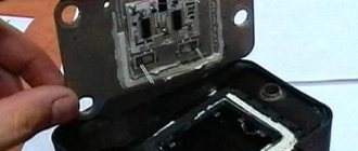
If during testing both secondary windings show integrity and serviceability, the reason for the inoperability of the coils may be a break in the soldering of the switch wires. Such damage is detected when the rear cover of the module is removed. If you have a soldering iron and know how to use it, you can restore the integrity of damaged contacts, while at the same time strengthening the rest. This, unfortunately, is the only failure of the ignition module that can be repaired.
Testing the ignition module can be done using simple do-it-yourself instruments. Based on our advice, you will be able to fully check both the module itself and other elements of the mechanism that may be the cause of the breakdown. We wish you success in this matter!
Why does the MH break down?
The ignition module fails due to the use of low-quality spark plugs, as well as due to the use of old high-voltage wires whose insulation has lost its properties.
If the MZ gets wet, for example, by driving a Niva along a ford, then the likelihood of it breaking is quite high.
In order for the ignition module to work much longer, it is necessary to change the spark plugs and high-voltage wires on time.
Possible causes of failure
The weak point of the ignition coils and modules is the secondary winding, which generates a high voltage pulse. A coil break or breakdown may occur in it. The following factors lead to this phenomenon:
- use of low-quality or unsuitable candles;
- operation with non-functioning high voltage wires;
- frequent attempts to check the spark.
The high-voltage pulse arising in the secondary winding must be realized (spent). If this does not happen (if the integrity of a high voltage wire is broken, for example), a high-energy electrical pulse seeks an outlet. He will find it, with a high degree of probability, in the thin secondary winding.
Often, a module malfunction occurs when the integrity of poor-quality factory soldering of wires going to the switch elements is violated. This happens from vibration. Also, the cause of non-working coils can be a banal contact failure in the incoming connector. Another factor leading to a malfunction of the ignition unit is often moisture that gets on the device during washing or driving in unusual conditions.
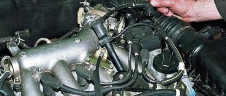
Connecting high voltage wires
The sequence of connecting the high-voltage wires plays a huge role, since the spark in the cylinder is supplied in a certain order, which is indicated by the crankshaft position sensor. As soon as the piston reaches TDC, a spark is supplied to it to ignite the air-fuel mixture.
Below is a diagram of how to connect high-voltage wires on a Niva.
Candle making options:
To increase productivity when creating these products, some technological features are used, which in theory can increase productivity, and as a result, the highest quality fuel combustion:
- Platinum coating. Allows you to increase the service life up to 50 thousand kilometers due to the fact that the surface becomes more resistant to the combustion products of the fuel mixture.
- Multi-contact spark plugs. Typically used in cars that are operated in regions with predominantly low temperatures. Such products make it possible to improve the starting of a cold car in the morning. In summer, it is recommended to replace them with regular ones.
Replacing the Niva 21214 timing chain on an injector with your own hands, video
Here we will talk about independently replacing the timing chain drive on a Niva 21214. The timing belt affects the operation of the entire car, so the importance of this unit should not be underestimated. Replacing a chain drive is a rather complicated process, which, however, can be done by any car enthusiast, provided that he follows the instructions and shows a little diligence.
A chain has significant advantages over a belt drive. These include, first of all, its reliability. While a belt can break, this rarely happens with a chain. Usually it just stretches. It lasts much longer than the belt, which means it needs to be changed less often. But still, the chain does not last forever, and after a while it also has to be replaced with a new one. When replacing the chain yourself, it is very important to set the marks correctly and follow safety precautions.
When to change the timing chain?
The manufacturer does not give clear recommendations regarding the timing of replacing the timing chain on the Niva. Experts assure that the need for replacement may arise no earlier than after 100,000 km. But it is very important to periodically carry out diagnostic procedures for chain transmission. It may well happen that the chain weakens. This will be noticeable by the characteristic sound that the running engine will make. First you need to try to tighten the chain. If this cannot be done in the usual way, replacement becomes necessary. In this case, you can contact a service center, where this repair will be carried out by professionals, or you can try to change the chain yourself. The latter option is preferable in terms of savings and gaining the necessary experience.
If the mark on the camshaft gear does not match the mark on the bearing housing, it's time to take action. The chain drive also needs to be replaced if chips or cracks appear on it. All this suggests that your chain has served its intended life and it is time to replace it.
So, you have decided that you will make the replacement yourself. What do you need to do next? First of all, go to the store and buy a new chain there. You can check the quality of the chain you are purchasing. We take the chain and place it flat on our palms. If its sagging exceeds 1 cm, you better look for consumables elsewhere. In addition to the chain itself, you will also have to buy a set of oil seals, a tensioner, dampers, and a set of gaskets. Then we prepare the tools that will be useful in the work and begin the repair.
Replacing the chain drive
- Place the car on a level surface. Open the hood. Disconnect the battery. Remove the air filter.
- The choke cable should be disconnected and moved away. It is also necessary to disconnect all electrical drives and pipes.
- Remove the fan, generator belt and pump roller. The belt should be thoroughly examined. If deep cracks or other damage is found on it, it must be replaced with a new one. Remove the tray protection and thoroughly clean its cover.
- Remove the valve plug. Unscrew the camshaft sprocket screw.
- Take a wrench and unscrew the ratchet nut.
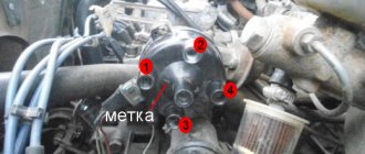
- Now we begin to rotate the crankshaft until the marks on it and on the engine casing completely coincide. Make sure that the marks also match on the bearing housing and camshaft sprockets.
Features of setting timing marks
Marks are marks and notches located on the gears of the gas distributor. For clarity, below is an example of installing a notch on a drive gear disk. It coincides with the center of the DPKV (crankshaft position sensor).
The marks on the camshaft pulley are fixed against the ebb on the bearing housing, which fixes the main shaft on the platform.