Print this article Font size 16
In our material today we will talk about how the ignition module on a VAZ 2114 is checked, how it works and why so much in the car depends on its functional state.
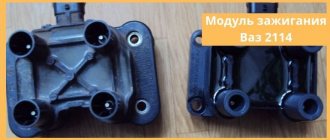
Ignition module
VAZ-2114 ignition module and its features
The passenger car ignition module is specially designed to improve the starting of a car engine.
Since two high-voltage coils operate as the main components of the module, it is often called the “ignition coil”. Let's look at the structure of this part:
- coils for generating high voltage;
- two-channel electronic switch;
- durable plastic case;
- low-voltage connector for supplying control pulses;
- terminals for connecting high-voltage wires to spark plugs.
The main operating elements of the ignition module are high-voltage coils that distribute the igniting spark to the spark plugs. This is possible thanks to the following design:
- Wires for high voltage transmission.
- Low voltage terminals.
- The windings on the core are secondary (for igniting the working mixture) and initial.
- Electrical steel core.
The mechanism of operation of the ignition coil is as follows:
- the electronic engine control unit collects all signals from the sensors located on it;
- The ECU generates a control signal;
- the signal goes directly to the ignition coil;
- that, in turn, forms a high-voltage voltage;
- voltage from the coil is supplied to the engine cylinder spark plug;
- the fuel-air mixture ignites;
- the engine starts.
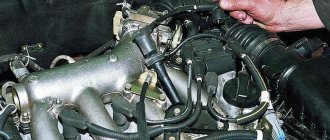
Even an inexperienced car enthusiast can find this part: just trace the path of one of the high-voltage wires - from the spark plug to the plastic case.
This housing houses the ignition module.
Design
The design of the ignition module is quite complex, since it combines technology and electrics. The device serves to create high voltage transmitted to the spark plugs. It is this supplied current that is the basis for ignition.
The operation of the module ensures fuel combustion and, accordingly, engine operation. In very simple terms, the car won’t go anywhere without the module.
For VAZ models, the use of two types of ignition modules is provided:
- Separate;
- Block.
Block ones differ in that the coils operate one per pair of spark plugs. These are the devices that are installed on the “fourteenth” model of the domestic automaker.
The coil distributes power to two candles at once, and its design includes the following elements:
- High voltage wires;
- Low voltage terminals;
- Secondary and primary winding;
- Core.
Separate modules, where the coils supply a separate circuit to each of the 4 sections, are distinguished by the output of high-voltage wires through a spring contact. Block ones are easier to check, they are easy to remove and return to their place.
It is noteworthy that with a size of 11x11x7 centimeters, this block weighs about 1.5 kilograms.
VAZ-2114 ignition module: various signs of malfunction
Experts note the main symptom of a faulty ignition coil is the absence of an igniting spark on the spark plugs. But, besides this, there are other signs by which one can judge that the module has failed:
- Lack of dynamics during engine acceleration.
- The appearance of failures in the operation of a car engine at the moment of sharply pressing the gas pedal with your foot so that the vehicle accelerates.
- A noticeable decrease in engine power (as they say, “the engine doesn’t pull”).
- “Swimming” of idle speed.
When the first signs of a malfunction of the described module appear, the owner of the VAZ-2114 should diagnose it. This can be done either independently at home or at the nearest service center for repairing cars of this model.
Oil pressure sensor (OPS)
The oil pressure sensor is located near the oil filler neck. The sensor serves as a signal to the driver about a decrease in oil pressure in the engine. When the pressure decreases, it sends a signal to the instrument panel and lights up the low oil pressure warning light.
Signs of DDM malfunction:
- Constant lighting of the oil pressure lamp;
- Oil leakage from the joint in the sensor;
How to diagnose the ignition coil on a VAZ-2114
As already mentioned, when the first signs of malfunctions appear in the VAZ-2114 ignition module, the vehicle owner should diagnose it. You can perform a similar procedure yourself at home using the following algorithm:
At home, all stages of the checks can be performed independently. The first stage is checking the spark plugs. It is carried out in the following sequence:
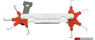
- We remove the spark plugs from their sockets - remove the tips of the high-voltage wires (a special spark plug wrench is suitable for this).
- We examine the candles.
- We clean them from possible soot.
- We set the correct distance between the electrodes.
- We check the spark plugs for operation using improvised means (for example, from a device made from a piezo lighter) or on a car engine with a working ignition system.
If the spark plugs are in good condition, you can proceed to the next stage of checking for faults in the ignition module.
The second step is to check the crankshaft sensor. This test is carried out using a multimeter, thanks to which two characteristics are checked - voltage and resistance. To do this proceed as follows:
- Remove the crankshaft sensor.
- Measure resistance:
- a special ohmmeter mode is installed on the device;
- the terminals of the device are connected to the ends of the winding, which is brought to the surface;
- with optimal sensor operation, digital readings will range from 500 Ohms to 700 Ohms.
- Measure voltage:
- switch the device to the mode for measuring alternating voltage;
- terminals are connected to the ends of the winding;
- any handy object made of metal should be passed along the body of the crankshaft sensor;
- When the sensor operates optimally, the device will show increased voltage readings because there will be a metal object nearby.
Otherwise, the faulty sensor will have to be replaced with a new one, because it also affects the operation of the VAZ-2114 ignition module. If after this there are still signs of coil malfunction, then you should proceed to the third stage of the test.
The third stage is checking the ignition coil itself. This part is checked as follows:
- The easiest way is to replace the coil with a new one;
- while the car engine is running, you can move the coil and knock on it (if there are visible changes in the functioning, it is time to judge a faulty contact in the coil itself);
- take measurements with a multimeter for resistance readings, such indicators are taken from paired coils - they should be identical, approximately equal to 5.4 kOhm.
What to do if you don’t have a multimeter, but you need to check the electrical circuit? Experts recommend using a twelve-volt light bulb. To do this, one of the wires coming from it should be connected to the terminal, and the second wire should be shorted to the motor housing. If the control light flickers when the starter starts, then everything is in working order.
If the car owner has problems performing such diagnostics himself, he can always turn to qualified specialists at a service station.
Other reasons
If, after checking the ignition module of an injection-type VAZ-2114 car, no malfunction was identified, then you should pay attention to breakdowns or improper operation of adjacent devices.
- Powertrain control unit. It happens that after an electrical short circuit, the ECU loses its internal settings. To restore functionality, you need to disconnect the “+” terminal from the battery and connect it again. The ECU will enter a temporary reboot, and the module's operation may be restored. It is also worth carrying out professional diagnostics of the on-board network.
- Crankshaft position sensor. An important source of pulse signals. Its data affects the distribution of voltage from the ECU to secondary devices. It is necessary to check the functionality of this element, its wiring, and the protective fuse. If necessary, replace faulty parts.
- Hall Sensor. This device is responsible for the distribution of pulses. Signals are generated due to contact connection during rotation of the device rod. Any deviations in the supply of signals affect the operation of the ignition module.
- Generator. The high charge current of this mechanism often leads to complete burnout of the secondary winding of the MC. The first problem may be a faulty fuse. If such a problem is detected, it is worth checking the amount of voltage coming from the generator.
The system, which includes a Hall sensor, DPKV and ignition module, works by calculating the position of the crankshaft. This is how the exact order of the spark cycle on the cylinders is achieved.
Important! Very often, the performance of the MH is affected by careless operation of this device. The cause of failure may be:
- Lack of contact with the “mass”. This occurs when the 3 bolts securing the device are insufficiently tensioned. Periodic loss of contact leads to a break in the circuit. The newly appeared contact causes the discharge of a current of greater strength. This leads to internal burnout of the secondary winding of the coils.
- Lack of contact on spark plug caps. A poor connection leads to contact vibration, often high-voltage wires fly out and short to ground. This leads to damage to the MZ discharge contactor.
- Poor contact or oxidation at the battery terminals. It also leads to a short-term but powerful discharge of the primary winding.
- Spark plug gap. The manufacturer sets a fixed spark plug gap. The maximum value for spark plugs installed on injection engines can be 1.3 mm. A large gap leads to a spark hitting the housing. The spark is simply deflected to the side. A small gap size can lead to breakdown of high-voltage wires or the ignition coil itself. The high voltage pulse current is simply discharged back into the circuit.
Many car enthusiasts try to disassemble and repair ignition modules themselves. With proper knowledge of electronics, only the discharge regulator can be repaired. The coils will have to be rewound. But the main difficulty lies in the subsequent sealing and insulation of the inductors. Any remaining cracks will cause breakdown and failure. It is better to purchase and replace the MZ with an exact analogue.
Methods for preventing the ignition module on a VAZ-2114
Malfunctions of automobile ignition coils on the VAZ-2114 can be avoided if preventive procedures are regularly carried out. These include:
- Periodic unraveling of high-voltage wires (associated with greatly increased internal resistance, as this can damage the module).
- Checking the spark gap between the electrodes of the spark plugs (if the distance between the electrodes changes, this will affect the efficient operation of the ignition coils).
If faulty spark plugs are identified, they are replaced, after which the car will function properly again.
Source
Camshaft sensor (DPRV) - phase sensor
Type of camshaft sensor
Type of camshaft sensor (DPRV) of VAZ 2114, 2113, 2115 cars mounted on the 2111 (l.5i) engine.
View of the camshaft position sensor (camshaft position sensor) of the VAZ 2114, 2113, 2115 passenger car mounted on the 11183-30 (l.6i) engine.
Why do you need a camshaft sensor (DPRV)?
DPRV (Camshaft Position Sensor) VAZ 2114, 2113, 2115 designed to generate a pulse by which the ECU calculates the top dead center (TDC) of the piston of the 1st cylinder during the compression stroke.
Sometimes this sensor is called a phase sensor. Connection diagram for the camshaft sensor (phase sensor) VAZ 2114, 2113, 2115 Pinout of the camshaft sensor (phase sensor) model 2111-3706040 Installation location of the camshaft sensor (phase sensor) VAZ 2114, 2113, 2115
More detailed information about the camshaft sensor can be found on this page site: Camshaft position sensor (phase sensor) VAZ 2114, 2115, 2113 8 valves
We check the ignition module on the 8-valve VAZ-2114 with our own hands: signs of malfunction
- VAZ 2114 ignition module and its purpose
- Possible reasons for failure of the ignition module
- Signs of coil malfunction
- How to check the malfunction of the VAZ 2114 ignition module on your own?
- Ignition module repair
- Useful video
A faulty ignition module (“coil”) is often to blame for engine malfunctions, instability of speed, and poor acceleration. How it works, how to check the ignition module of a VAZ 2114 and how to replace it in case of a malfunction will be discussed in this article.
Speed sensor type 2111-3843010-00
Design of the speed sensor VAZ 2114, 2113, 2115 models 2111-3843010-00
What is a speed sensor used for?
The speed sensor of a VAZ 2114, 2113, 2115 passenger car produces a pulse signal that informs the ECU about the vehicle's driving speed. DSA installed on the gearbox
When the drive wheels rotate, the speed sensor generates six pulses per meter of vehicle movement. The ECU determines the speed of the vehicle based on the pulse repetition rate.
If the DSA circuits malfunction, the controller stores its code in its memory and turns on the alarm.
Speed sensor installation location
Speed sensor connection diagram
Speed sensor terminal pinout
The pinout of the speed sensor connector terminals has the following designations:
- From the main relay - plus (“+”);
- Signal output to ECU;
- Mass - minus (“-“).
Examination
It is a mistake to assume that damage to high-voltage wires does not in any way affect the condition of the module itself. Many people think of simply replacing high-voltage elements, but in reality they will still have to change the module.
This is explained by the fact that damaged or defective wires direct the wrong current, the configuration of which does not correspond to the necessary parameters. As a result, the spark hits inaccurately or ineffectively, causing the module to burn out and become unusable.
In general, the best option for checking the ignition module on a VAZ 2114 is to use an oscilloscope . But, firstly, not every driver has it, and secondly, few people can use them. Therefore, we will carry out the check using improvised means:
- 12-volt light bulb;
- Tester (available for little money at any auto parts store).
Let's start with preliminary manipulations with the accompanying elements of the ignition module.
- Check the wiring harness. It is disconnected and the voltage indicator is checked.
- To do this, fix the tester on contact A, and connect the other terminal to engine ground.
- In normal condition, the voltage reading will be 12V.
- If there is no voltage, most likely the fuse has blown.
- If everything is fine, transfer the terminals of your tester to contacts A and B, start the car. In this case, the starter should turn and the 12-volt light should blink.
- In the absence of these phenomena, we can talk about the presence of a break in circuit A of the contacts.
Next we go to the ignition module itself.
There are several ways to check the condition of your unit. Therefore, let's look at each of them.
- Set the tester to ohmmeter mode. Use it to measure the resistance on the high-voltage lines going to cylinders 1 and 4, and then, by analogy, to the wiring of cylinders 2 and 3. In normal condition, the device will give you readings from 5.2 to 5.5 ohms.
- Give the device a gentle tug. Thus, you will shake the wiring block and the module. Moreover, this must be done in the operating mode of the power unit. If the device works without obstruction when loosened, everything is fine, you are lucky. If not, you will again have to study the condition of the wiring.
Third way
The third method is considered the simplest, since it involves replacing your device with a similar one that works exactly. But to do this, you have to find a full-fledged twin. We are talking about an ignition module from a car similar to yours in terms of year of manufacture and power unit used. It’s just that 1.5-liter engines have modules, and 1.6-liter engines have coils.
But to replace a module with a module, you will have to first dismantle yours. This is done as follows:
- Remove the negative terminal from the battery, which will allow you to turn off the power to the car;
- Disconnect four high voltages from the ignition module;
- Disconnect the wire block. To do this, you need to release the special clamp that holds the block on the module;
- Next, unscrew the three nuts. With their help, the module is held on the bracket;
- There are three long pins on the bracket, from which the module can simply be pulled off.
Having dismantled your module, you can put another unit in its place, thereby verifying the functionality of that one and the malfunction of yours.
Installation
The module is installed strictly in the reverse order of dismantling. It is important to take into account three rules.
- After installing the module, look at the surface of the device. It shows numbers from 1 to 4. These are the designations of cylinder numbers.
- At the ends of the high-voltage bars there are similar numbers - from 1 to 4. They serve as a guide to determine which high-voltage wire is connected to which socket on the module.
- No experiments. Everything is connected strictly in accordance with the marks - 1 to 1, 2 to 2, and so on.
In fact, replacing the ignition module on a VAZ 2114 is quite easy. You don't need to be a professional auto mechanic to do this. Just follow the basic rules for dismantling and installation, and check the device before spending money and replacing it with a new one. It is not a fact that the culprit of problems with your car will be the module you are sinning with.
This table will allow you to check whether the wires from the ignition module to the cylinders are connected correctly.
In a car, each part is assigned certain functions. The ignition module also performs a number of important tasks, for example, when it breaks down, the engine is not able to work properly and it becomes difficult to start the car.
Oxygen sensor (DC, lambda probe)
An oxygen sensor, also known as a lambda probe, is installed in the exhaust manifold and is designed to record exhaust carbon dioxide gases. In some car models that were produced after 2010. There are 2 oxygen sensors. Serves to adjust the air-fuel mixture based on carbon dioxide measurements.
Signs of DC malfunction:
- High fuel consumption;
- Loss of engine power;
- Difficult starting of the internal combustion engine;
VAZ models 8 and 16 valves
Despite the similarity in engine design, the ignition system of the 1.5-liter injection 16-valve engine differs from the 1.6 16-valve engine. The 1.6 liter engine uses an electronic contactless ignition system with individual coils on each spark plug. Therefore, there was no need for an ignition module. Such a system is more reliable and cheaper to operate, since if one coil fails, there is no need to replace the entire module.
The 16-valve 1.5-liter VAZ 2112 injection engine used the same non-contact ignition system as the 8-valve engine, but a different ignition module was installed. Its catalog number is 2112-3705010. The design of the module remains the same - two ignition coils (for cylinders 1-4 and 2-3) plus switch keys in a single block. The spark is supplied to the cylinders in pairs using the idle spark method. This means that sparking occurs in two cylinders simultaneously - in one on the compression stroke (working spark), in the second on the exhaust stroke (idle spark).
Purpose
The ignition module is used to generate a spark and serves as a kind of step-up transformer that raises the voltage from 12 to 40,000 volts. Such a high voltage is necessary to form a powerful spark in the combustion chamber and effectively ignite the fuel mixture.
There is a Lada Super Auto car built on the basis of 2114 with a Priora engine; this engine does not have an ignition module, and instead uses an individual ignition coil, which is installed on each cylinder.
The ignition module, unlike the IKZ, is responsible for 4 cylinders at once.
Useful video
You can find interesting information by watching the additional video below: https://www.youtube.com/watch?v=pNyBny-_HoQ
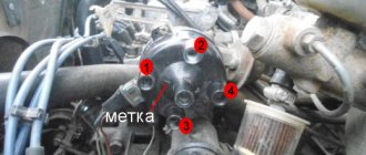
On a car with contactless ignition, everything is even easier; you don’t have to remove the wheels, but you will need an assistant. It is necessary to find the compression stroke of the fourth cylinder. To do this, insert a rubber cone into the spark plug hole and turn the ratchet. Pushing out the cone will mean that the compression stroke has been found.
Having illuminated the spark plug hole, we align the longest mark of the cover with the mark of the pulley. We set the breaker to the appropriate clock and check the operation of the system according to the fourth point described above.
Frequent malfunctions of the VAZ-2114 ignition module
The following malfunctions occur in the VAZ-2114 ignition module:
- intermittency is formed at idle;
- power indicators leave much to be desired;
- the engine is not working correctly;
- in the paired operating mechanism, the cylinders are acting up (that is, the functioning of only one pair of cylinders can be heard);
- if the Check Engine light comes on.
If you suspect a faulty factory module in your car, then it's time to check the ignition module. It doesn’t hurt to make sure with your own hands that the wires are connected correctly and firmly; check that the spark plugs remain intact and are not damaged. Before you begin diagnostics and repair work, you need to stock up on protective equipment that will protect you from dangerous situations - the tool must be treated with insulating material, and gloves are required.
Signs of breakdown
Disassembled
In fact, the symptoms of a malfunction in the VAZ 2114 ignition module are in many ways similar to the breakdown of other units. For example, you may observe the following phenomena:
- The engine is tripping;
- The car stalls at idle;
- There are problems when trying to start the car, etc.
That is, in fact, it may not be a module at all. Therefore, the only correct solution is to check the ignition module on your VAZ 2114.
How to check the malfunction of the VAZ 2114 ignition module on your own?
The easiest way to check the device without removing it is to diagnose it at the moment the power unit is tripped. When the motor begins to operate unstably, it is necessary to disconnect the connector elements from each component of the module one by one. If the connector is disconnected from a functioning device, the operation of the engine will change. Dips will appear, and the unstable operation of the unit will increase. When the non-working element of the MH is disconnected, the motor will operate in the same way.
There is another simple diagnostic method, its principle is as follows:
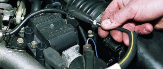
- You will need an assistant to check. The spark plug is removed from the seat. The high-voltage cable is disconnected from the device.
- Then the disconnected wire is connected to a spark plug, which is applied to the body of the power unit.
- The machine motor is starting, you need to make sure that a spark hits the spark plug. If it passes, a blue light will appear between the device and the surface of the power unit, its formation is accompanied by a crackling sound. If there is no spark, then the spark plugs, high-voltage cable and module must be diagnosed.
In the absence of special equipment, diagnostics of the MH can be performed using a control light indicator designed for 12 volts. One conductor from the lamp is connected to the pin of connector A, and the second is connected to ground for grounding. An assistant must start the power unit or rotate the starter mechanism. If the light flickers when performing these steps, then the device is working. Similar actions must be done with another contact.
The channel “Diary of an Auto Electrician” spoke about self-diagnosis of ignition modules, as well as other elements of the system.
Checking the ignition unit with a multimeter
Diagnostics is carried out in the following order:
- The car engine is started.
- The tester switch must be set to DC measurement mode, the limit should be up to tens of volts.
- One of the contacts of the multimeter is connected to connector D on the coil, and the other goes to ground. You can use a car body or a cylinder block as a mass. If there is power, the diagnostic tool display will show 12 volts.
- Then the tester switches to the ohmmeter operating mode, the range of values is up to tens of ohms.
- One contact of the diagnostic tool is connected to output C, and the second goes to ground. If the device is operational, the test will show a value of less than 1 Ohm.
- At the next stage, the tester must be switched to voltmeter mode. The range of values is up to tens of volts.
- One of the contacts goes to the output marked B, and the second is connected to ground.
- If the diagnostics show that the voltage is less than 0.3 volts, then the device is working. This indicates a clear signal passage from the Hall controller. Finally, you can perform a similar test, only with connector A. The results should be identical.
Direct check of secondary coils for breakdown
To diagnose secondary elements of the MH for breakdown, you will also need a tester:
- All connected conductors must be disconnected from the device connectors.
- Diagnostic equipment is set to ohmmeter mode, the range of values is up to tens of ohms.
- The contact probes of the tester must be connected in turn to the paired connectors of the module. For example, in the second and third, as well as in the first and fourth.
- If the diagnostics showed the same results, then all windings are operational. The resistance parameter should be about 5.4 kOhm. If the values obtained are higher, this indicates an internal break in the device. With lower parameters, we can conclude that there is a breakdown.
Igor Belov shared effective options for diagnosing MH in garage conditions.
System diagnostics
If signs of damage are detected, there is no need to immediately remove and repair the MH. First, the spark plugs must be checked; to do this, they are removed from their sockets, and the high-voltage wires are first disconnected from the spark plugs. The spark plugs should be carefully inspected, cleaned of carbon and deposits, and then checked again.
Brown color is acceptable on these devices, but soot and carbon deposits are undesirable. If necessary, you also need to adjust the gap between the element itself and the electrodes. More detailed instructions for diagnosing the module yourself are given in the video below (the author of the video is Alexey Romanov).
How to quickly check the performance of the coil at home:
- Of course, the fastest and easiest way would be to install a unit that is known to work, but it is unlikely that anyone will carry a working spare device with them.
- While the engine is running, try tapping the coil. If you notice changes in the operation of the motor, this indicates that there is poor contact inside the device.
- The most accurate results can be obtained from diagnostics with a multimeter. You need to measure the resistance of the paired terminals of the coils, in particular the first and fourth, as well as the second and third. The parameter should be 5.4 kOhm; if the values differ, the device needs to be repaired or replaced.
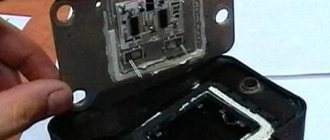
MODULE DEVICE
Design (circuit) of the VAZ 2114 ignition module The device includes two coils, the main task of which is to generate high voltage.
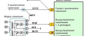
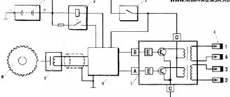
A two-channel electronic switch helps them in this. All these parts are contained in a housing made of durable plastic. The housing has a low-voltage connector for connecting the supply voltage and supplying control pulses. There are also leads for connecting high-voltage wires that are connected to the spark plugs. Electrical diagram of the VAZ 2114 starting system The figure shows an electrical diagram of the VAZ 2114 starting system. As can be seen from the figure, it consists of:
- Battery;
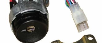
- Ignition switch;
- Relay that turns on the ignition;
- Hall Sensor;
- Semiconductor signal receiver from the sensor;
- Electronic switch;
- Ignition module.
- High voltage terminals.
The electrical diagram also shows the fuses of the power supply circuits of the electronic units. Let's try to look at the device and operating principle of the ignition coil. As already noted, there are two of them in the block; they are identical in design. The ignition coil circuits of one and the other are also absolutely identical. The principle of operation of the ignition coil remains the same. Both consist of cores made of electrical steel. Two windings are wound on them. One of them is low-voltage, and the second produces high-voltage voltage to ignite the working mixture.
The ignition coil connection circuit is made in such a way that one end of the low-voltage winding is connected to the supply voltage, and the other end of these windings is connected to a transistor generator. Each coil has its own transistor. The high-voltage leads are connected directly to the spark plugs; each winding supplies energy to two spark plugs. One of them outputs pulses to cylinders 1 and 4, and the second to cylinders 2 and 3.
The wires on the ignition module are arranged as follows. Contacts A and B receive control pulses from the electronic switch, pin D receives power from the machine’s on-board network. The terminal marked with the letter C is connected to the vehicle ground.
Connection diagram
Mechanism connection diagram
You can find the module itself using high-voltage cables - from the spark plugs they go straight to it. The diagram given in this article will allow you to easily replace the mechanism. The device connection procedure can be carried out using one of two methods. When the short circuit is dismantled and when it is located at the installation site in the engine compartment of the vehicle.
If the module is in front of you:
- Contacts numbered 1 and 4 go to one winding, as for contacts 2 and 3 - they are connected to another winding.
- After this, the leftmost high-voltage cable is connected to cylinder 1 (the bottom one in the diagram).
- Another high-voltage wire is connected to the second cylinder, only this time it’s the top one.
- The right high-voltage wire (top) goes to cylinder 3.
- Accordingly, the lower high-voltage cable must be connected to the last, fourth cylinder.
If the assembly is connected to a motor, then the pinout of high-voltage cables will be more complicated, since the mechanism itself is installed at an angle:
- The central lower wire is connected to the first cylinder.
- To the second - left.
- The third contact is connected to the top contact.
- And to the last, fourth cylinder - the right one.
Of course, the first installation method will be simpler, especially if you consider that high-voltage cables must be connected very carefully and carefully. If you accidentally confuse, this may lead to the inability to start the power unit, which is more sad - to the occurrence of malfunctions
As for directly purchasing a new short circuit, this pleasure in general is not cheap. Today, the cost of a node varies from 700 to 1000 or more rubles, much depends on the region of residence. So before changing the node, you can try to restore its functionality:
Selected aspects of technical operation
Often the reason for many calls to the service station is not so much malfunctions in the high-voltage wires, but rather the incorrect operation of the Kalina ignition module. To carry out diagnostics, you can go to a service center or pick up the tools yourself. One of these is a multimeter used to measure the actual resistance level on the 8-cell pins. engine. To obtain correct measurement results, it is necessary to carry out 2 times.
The ignition system can be damaged in any part of the circuit, so monitoring must be careful. It all starts with checking that the winding is properly connected to ground. It is necessary to carefully insert the contacts, focusing on the indicators of the device. Then one of the contact terminals of the device is connected to the central contact of the spark plug coil. In this case, the second contact is attached to ground.
Why does the MH fail?
The cause of failure of the ignition module is aging and insulation breakdown. Most often, the MZ fails along a vein of broken high-voltage wires, which causes a spark from the module to hit the housing, thereby exposing it to excessive currents.
Old spark plugs have high resistance due to carbon deposits, which can cause a breakdown in the housing, which leads to failure of the ignition module.
You should change spark plugs every 30-40 thousand kilometers, and also inspect high-voltage wires for breakdown.
Repair or replacement?
As the practice and experience of car repair technicians shows, most often it is not possible to repair this device. The module can only be replaced. If you follow the principle, it is possible to carry out repairs, but it will take a lot of time, effort and even money.
Installing the module
The best option is to purchase a new device. It costs around 2-4 thousand rubles. It all depends on the manufacturer and condition. You can buy a brand new one, although many people prefer used devices. Here the choice is yours.
conclusions
As a rule, the ignition module is not restored and is simply replaced with a new one. There is no guarantee that he won't start bucking again. This will save a lot of gray brain cells and save a lot of personal time, which can be spent on something more necessary. It's better to buy a new one and not worry.
However, as children, we all loved to take toys apart to find out what was inside and how everything worked. It’s not a pity to try to disassemble a broken unit, but still throw it away if nothing works. But if you repair it, you will get so much pleasure and pride in yourself!
How to check the ignition coil of a VAZ
If the ignition coil is faulty, the engine will not start. A characteristic sign of a faulty coil is its increased temperature when the ignition is turned off. This is easy to determine by touch.
Signs of a faulty ignition module may include the following:
- hesitant engine starting or failure to start;
- failures during sudden changes in speed;
- high fuel consumption;
- two cylinders do not work, the engine is feverish;
- lack of dynamics;
- a sharp drop in power;
- drop in power and thrust after warming up.
These symptoms may not only be caused by the ignition module. To determine the malfunction, it is enough to spend a few minutes diagnosing spark plugs, high-voltage wires and caps. This will eliminate the remaining elements of the ignition system and make sure that it is the ignition module that is faulty.
Checking the ignition coil is performed in one of 2 ways. The simplest one is to remove the central wire from the breaker-distributor, bring it to the motor housing and turn it with the starter, and a running spark should appear. After this, we check the energy supply to a separate spark plug, for which we unscrew the working spark plug, bring its contact to ground and attempt to start the engine. In this case, the spark should come from the wire to ground. If it is absent, the reason will be a malfunction of a system element such as the ignition coil.
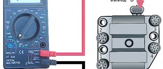
To check the module in the second way, we only need a multimeter, then follow the step-by-step instructions:
- We check the power supply and the presence of pulses supplied from the ECU. We check the power between the central terminal (15) of the wire block connected to the module and the engine ground. When the ignition is on, the voltage should not be less than 12 V. Otherwise, either the battery is dead or the ECU does not work.
- We check the pulses from the ECU on the wiring block. We install one tester probe on connector 15, the second on the far right, then on the far left. The assistant cranks the engine with the starter, and at this time we record short-term voltage surges with a tester. If there are no impulses from the ECU, it is he who is to blame.
- We check the resistance on the secondary windings of the coils. We put the tester in resistance measurement mode and measure it at the high-voltage terminals of the module cover. Between pins 1 and 4 and pins 2-3, the resistance should be 5.4 kOhm. Otherwise, the module must be replaced.
- We check the resistance of the primary windings between contacts 15 and the rightmost, then the leftmost terminals. Nominal - 0.5 Ohm. Deviation is not allowed.
- Check the module for a short circuit. In ohmmeter mode, install one multimeter probe on the central terminal, the second on the metal body. There shouldn't be any resistance. If the device detects at least some resistance (other than unity or infinity), the module must be replaced.
Useful: VAZ cooling fan connection diagram
Mass air flow sensor model 21083-1130010-01
Design of mass air flow sensor (MAF) type 21083-1130010-01
The engine control system uses a hot-wire mass air flow sensor (MAF). It is located between the air filter and the intake pipe hose.
The mass air flow sensor pulse is a direct current voltage, the size of which depends on the volume and direction of air movement passing through the mass air flow sensor. With a forward air flow, the voltage of the sensor output signal changes in the range of 1...5 V. With a reverse air flow, the voltage of the sensor output pulse changes in the range of 0...1 V. The diagnostic device reads the sensor readings as air flow in kilograms per hour.
When a breakdown of the mass air flow sensor circuit occurs, the ECU stores its code in its memory and turns on the warning light. In this case, the ECU calculates the mass air flow value based on the crankshaft speed and throttle position.
Connection diagram for mass air flow sensor (MAF) VAZ 2114, 2113, 2115 type 21083-1130010
Installation location of the mass air flow sensor (MAF)
Detailed information about the mass air flow sensor is located on the page of this site called DMRV 2114, 2113, 2115 8 valves
Built-in air temperature sensor in the mass air flow sensor
The air temperature sensor is built into the air flow sensor. The sensitive element is a thermistor (a resistor that changes resistance depending on temperature) mounted in the air flow. The output pulse of the DTV ECU connected to the con is a direct current voltage in the range 0...5 V, the size of which depends on the temperature of the air passing through the sensor.
When a malfunction occurs in the DTV circuit, the controller stores its code in its memory and turns on the alarm. In this case, the ECU replaces the sensor readings with a fixed air temperature value of 33 oC.
| Table of dependence of DTV resistance on intake air temperature (±10%) | |
| Air temperature, oС | Resistance, kOhm |
| — 40 | 39,2 |
| — 30 | 23 |
| — 20 | 13,9 |
| — 10 | 8,6 |
| 0 | 5,5 |
| + 10 | 3,6 |
| + 20 | 2,4 |
| + 30 | 1,7 |
| + 40 | 1,2 |
| + 50 | 0,84 |
| + 60 | 0,6 |
| + 70 | 0,45 |
| + 80 | 0,34 |
| + 90 | 0,26 |
| + 100 | 0,2 |
| + 110 | 0,16 |
| + 120 | 0,13 |
Operation in various conditions
Many inexperienced drivers, not understanding the essence of the breakdown, decide that an expensive replacement of the ignition switch or the wiring as a whole is necessary. Experienced drivers advise not to rush to conclusions. If, due to various circumstances, the ignition coil fails, the corresponding indicator lights up on the dashboard. The first thing the driver should do in such a situation is to drive the car into the garage and open the hood.
Often spark plugs fail due to a power surge or short circuit. As a result, the spark does not travel properly throughout the system. A number of other circumstances can cause a similar problem:
- the car was damaged in an accident;
- replacement of spark plugs may be required after lightning strikes the car;
- poor-quality previous repairs;
- use of non-original spare parts;
- failure to comply with technical inspection deadlines at the service center.
Regardless of the reason, the ignition circuit needs a full analysis. Often the problem is complex. That is why, if the driver does not have enough technical experience, the first decision that comes to mind should not be accepted as the only correct one.