The power supply system is part of the electronic engine management system, which is described in detail in a separate “Repair and Maintenance Manual for the Engine Management System with Multiport Fuel Injection.”
FUEL SUPPLY SYSTEM
The function of the fuel supply system is to ensure that the required amount of fuel is supplied to the engine at all operating conditions. Fuel is supplied to the engine by injectors installed in the intake pipe.
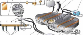
Rice. 2-62. Fuel supply system with distributed injection: 1 —
fitting for monitoring fuel pressure; 2 — injector ramp; 3 — fuel pressure regulator; 4 — electric fuel pump; 5 - fuel filter; 6 — fuel drain line; 7 — fuel supply line; 8 — nozzles
The fuel supply system (Fig. 2-62) includes: electric fuel pump 4, fuel filter 5, fuel lines (supply 7 and drain 6), injector ramp 2 with fuel injectors 8, fuel pressure regulator 3 and fuel pressure control fitting 1.
An electric fuel pump installed in the fuel tank supplies fuel through the main fuel filter and the fuel supply line to the injector rail.
The fuel pressure regulator maintains a constant pressure difference between the inlet pipe and the injection rail. The fuel pressure supplied to the injectors is within 300+6 kPa when the engine is not running. Excess fuel beyond that required by the injectors is returned to the fuel tank through a separate drain line.
Before servicing fuel equipment, it is necessary to relieve the pressure in the fuel supply system.
When disconnecting fuel lines, do not allow fuel to spill. To do this, wrap the ends of the tubes with a rag.
The procedure for relieving pressure in the fuel supply system:
1. Engage neutral gear and brake the vehicle with the parking brake.
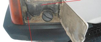
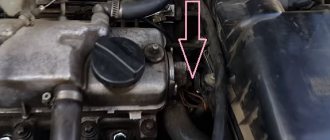
2. Disconnect the wires from the electric fuel pump (see Fig. 2-63), to do this, tilt the rear seat cushion forward and remove the electric fuel pump flap.
3. Start the engine and let it idle until it stops due to fuel exhaustion.
4. Turn on the starter for 3 seconds to relieve pressure in the pipelines. After this, you can safely work on the fuel supply system.
5. After releasing the pressure and completing the work, connect the wires to the electric fuel pump.
Rice. 2-63. Location of the electric fuel pump
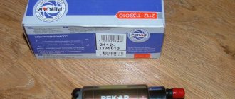
Electric fuel pump. The system uses a turbine-type electric fuel pump. The pump supplies fuel from the fuel tank through the main fuel filter to the injector rail. Excess fuel is returned to the gas tank through a separate drain line.
The electric fuel pump is switched on by the controller via a relay. When the ignition key is set to the IGNITION or STARTER position after being in the OFF position for more than 15 seconds, the controller energizes the relay for 3 seconds to create the required fuel pressure in the injector rail.
If the engine does not start cranking during this time, the controller turns off the relay and waits for cranking to begin. After it starts, the controller turns on the relay again.
Fuel filter 1 (Fig. 2-64) is installed under the underbody near the fuel tank 2. The filter is built into the supply line between the electric fuel pump and the fuel rail.
The filter has a steel body with threaded fittings at both ends. The filter element is made of paper and is designed to trap particles that could cause problems with the injection system.
Rice. 2-64. Fuel filter location: 1 - fuel filter; 2 - fuel tank
Removing the fuel filter:
1. Relieve pressure in the fuel supply system (see above).
2. Unscrew the nuts securing the fuel pipes to the filter. Avoid losing the O-rings installed between the filter and the tube tips.
ATTENTION. Be sure to use a second wrench on the fuel filter side when loosening the fastening nuts.
3. Remove the filter mounting clamp.
Installing the fuel filter
Check the O-rings for cuts, nicks or abrasions. Replace rings if necessary.
1. Install the filter so that the arrow on its body corresponds to the direction of fuel supply, and secure the filter with a clamp.
2. Attach the fuel pipes to the filter, tightening the fastening nuts to a torque of 20-34 Nm.
ATTENTION. Be sure to use a second wrench on the fuel filter side when tightening the fastening nuts.
3. By applying +12 V voltage to the pGc contact of the diagnostic block, turn on the electric fuel pump and make sure there are no fuel leaks.
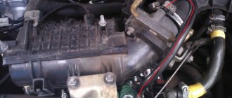
Removing the injector ramp
When removing the ramp, be careful not to damage the connector contacts and injector nozzles.
Keep dirt and foreign materials away from open pipes and ducts. During maintenance, close the fittings and openings with plugs.
Before removal, the injector rail can be cleaned with a spray of engine cleaner. Do not dip the ramp into cleaning solvent.
1. Relieve pressure in the fuel supply system.
2. Turn off the ignition.
3. Disconnect the wire from the negative terminal of the battery.
4. Disconnect the throttle valve drive from the throttle pipe and the receiver.
5. Disconnect the inlet pipe hose from the throttle pipe.
6. Unscrew the nuts securing the throttle pipe to the receiver and, without disconnecting the hoses with coolant, remove the throttle pipe from the receiver.
7. Remove the fuel supply and drain pipes, disconnecting them from the injector ramp, pressure regulator and from the bracket on the cylinder head.
ATTENTION. Be sure to use a second wrench on the side of the fuel supply fitting of the fuel rail when unscrewing the union nut of the fuel pipe.
8. Disconnect the vacuum hose from the pressure regulator.
9. Unscrew the nuts securing the receiver and remove it from the inlet pipe.
10. Remove the injector wiring harness by disconnecting it from the injection system and injector harness.
11. Unscrew the bolts securing the injector ramp and remove it.
ATTENTION. If the injector has separated from the rail and remains in the intake pipe, both O-rings and the injector retainer must be replaced.
Installing the injector ramp:
1. Replace and lubricate the new injector sealing rings with engine oil, install the fuel rail assembly on the cylinder head and secure with bolts, tightening them to a torque of 9-13 Nm.
Supply system
The power supply system is part of the electronic engine management system, which is described in detail in a separate “Repair and Maintenance Manual for the Engine Management System with Multiport Fuel Injection.”
FUEL SUPPLY SYSTEM
The function of the fuel supply system is to ensure that the required amount of fuel is supplied to the engine at all operating conditions. Fuel is supplied to the engine by injectors installed in the intake pipe.
Rice. 2-62. Fuel supply system with distributed injection: 1 —
fitting for monitoring fuel pressure; 2 — injector ramp; 3 — fuel pressure regulator; 4 — electric fuel pump; 5 - fuel filter; 6 — fuel drain line; 7 — fuel supply line; 8 — nozzles
The fuel supply system (Fig. 2-62) includes: electric fuel pump 4, fuel filter 5, fuel lines (supply 7 and drain 6), injector ramp 2 with fuel injectors 8, fuel pressure regulator 3 and fuel pressure control fitting 1.
An electric fuel pump installed in the fuel tank supplies fuel through the main fuel filter and the fuel supply line to the injector rail.
The fuel pressure regulator maintains a constant pressure difference between the inlet pipe and the injection rail. The fuel pressure supplied to the injectors is within 300+6 kPa when the engine is not running. Excess fuel beyond that required by the injectors is returned to the fuel tank through a separate drain line.
Before servicing fuel equipment, it is necessary to relieve the pressure in the fuel supply system.
When disconnecting fuel lines, do not allow fuel to spill. To do this, wrap the ends of the tubes with a rag.
The procedure for relieving pressure in the fuel supply system:
1. Engage neutral gear and brake the vehicle with the parking brake.
2. Disconnect the wires from the electric fuel pump (see Fig. 2-63), to do this, tilt the rear seat cushion forward and remove the electric fuel pump flap.
3. Start the engine and let it idle until it stops due to fuel exhaustion.
4. Turn on the starter for 3 seconds to relieve pressure in the pipelines. After this, you can safely work on the fuel supply system.
5. After releasing the pressure and completing the work, connect the wires to the electric fuel pump.
Rice. 2-63. Location of the electric fuel pump
Electric fuel pump. The system uses a turbine-type electric fuel pump. The pump supplies fuel from the fuel tank through the main fuel filter to the injector rail. Excess fuel is returned to the gas tank through a separate drain line.
The electric fuel pump is switched on by the controller via a relay. When the ignition key is set to the IGNITION or STARTER position after being in the OFF position for more than 15 seconds, the controller energizes the relay for 3 seconds to create the required fuel pressure in the injector rail.
If the engine does not start cranking during this time, the controller turns off the relay and waits for cranking to begin. After it starts, the controller turns on the relay again.
Fuel filter 1 (Fig. 2-64) is installed under the underbody near the fuel tank 2. The filter is built into the supply line between the electric fuel pump and the fuel rail.
The filter has a steel body with threaded fittings at both ends. The filter element is made of paper and is designed to trap particles that could cause problems with the injection system.
Rice. 2-64. Fuel filter location: 1 - fuel filter; 2 - fuel tank
Removing the fuel filter:
1. Relieve pressure in the fuel supply system (see above).
2. Unscrew the nuts securing the fuel pipes to the filter. Avoid losing the O-rings installed between the filter and the tube tips.
ATTENTION. Be sure to use a second wrench on the fuel filter side when loosening the fastening nuts.
3. Remove the filter mounting clamp.
Installing the fuel filter
Check the O-rings for cuts, nicks or abrasions. Replace rings if necessary.
1. Install the filter so that the arrow on its body corresponds to the direction of fuel supply, and secure the filter with a clamp.
2. Attach the fuel pipes to the filter, tightening the fastening nuts to a torque of 20-34 Nm.
ATTENTION. Be sure to use a second wrench on the fuel filter side when tightening the fastening nuts.
3. By applying +12 V voltage to the pGc contact of the diagnostic block, turn on the electric fuel pump and make sure there are no fuel leaks.
Removing the injector ramp
When removing the ramp, be careful not to damage the connector contacts and injector nozzles.
Keep dirt and foreign materials away from open pipes and ducts. During maintenance, close the fittings and openings with plugs.
Before removal, the injector rail can be cleaned with a spray of engine cleaner. Do not dip the ramp into cleaning solvent.
1. Relieve pressure in the fuel supply system.
2. Turn off the ignition.
3. Disconnect the wire from the negative terminal of the battery.
4. Disconnect the throttle valve drive from the throttle pipe and the receiver.
5. Disconnect the inlet pipe hose from the throttle pipe.
6. Unscrew the nuts securing the throttle pipe to the receiver and, without disconnecting the hoses with coolant, remove the throttle pipe from the receiver.
7. Remove the fuel supply and drain pipes, disconnecting them from the injector ramp, pressure regulator and from the bracket on the cylinder head.
ATTENTION. Be sure to use a second wrench on the side of the fuel supply fitting of the fuel rail when unscrewing the union nut of the fuel pipe.
8. Disconnect the vacuum hose from the pressure regulator.
9. Unscrew the nuts securing the receiver and remove it from the inlet pipe.
10. Remove the injector wiring harness by disconnecting it from the injection system and injector harness.
11. Unscrew the bolts securing the injector ramp and remove it.
ATTENTION. If the injector has separated from the rail and remains in the intake pipe, both O-rings and the injector retainer must be replaced.
Installing the injector ramp:
1. Replace and lubricate the new injector sealing rings with engine oil, install the fuel rail assembly on the cylinder head and secure with bolts, tightening them to a torque of 9-13 Nm.
2. Connect the injector wiring harness.
3. Install the receiver.
4. Install the fuel pipes by tightening the union nuts attaching to the ramp and pressure regulator to a torque of 20-34 Nm.
ATTENTION. Check fuel pipe O-rings for cuts, nicks or abrasions. Replace if necessary.
Be sure to use a second wrench on the side of the ramp fitting when tightening the fuel pipe tension nut.
5. Install the pressure regulator vacuum hose.
6. Install the throttle pipe on the receiver and secure it with nuts.
7. Connect the intake pipe hose to the throttle pipe.
8. Install the throttle valve actuator and check its operation.
9. Connect the wire to the negative terminal of the battery.
10. By applying +12 V voltage to the pGc contact of the diagnostic block, turn on the electric fuel pump and make sure there are no fuel leaks.
The injector (Fig. 2-65) of the distributed injection system is an electromagnetic device that meteres the supply of fuel under pressure into the engine intake pipe.
Lada 2115 Samara 2 Sport › Logbook › Fuel system and extending the life of the gas tank
After installing the power unit on the car, it came to a complete revision and replacement of some elements of the fuel system.
The first thing I decided to do was repair the fuel tank. It was removed from the body back in the summer of 2013, and had the following appearance: After washing the tank and visually inspecting its condition, a slight deformation of the bottom in the area of the fuel pump module was revealed. By its appearance, we can confidently say that it was formed when a car collided with a road obstacle. Straightening out the dent was not difficult; for this I used a metal rod, a hammer and a copper block used in plumbing.
In addition, I paid attention to the condition of the metal in the area of the weld along the entire perimeter of the tank. Crevice corrosion was present almost everywhere. This upset me a little, since this problem had to be fixed, and in the first minutes I didn’t even know how to do it. But, after further thinking about this issue, I came up with an idea.
The manufacturing technology of the fuel tank involves joining the parts of the body with an overlap, and applying one weld with through penetration, as shown in the following figure.
The described development of events is confirmed in practice and has the following picture:
To avoid adverse consequences and extend the life of the gas tank, I decided to get rid of the potential source of corrosion by cutting off all the metal from the outside after the weld.
The procedure was performed with extreme caution in order to avoid breaking the seal of the tank. I cut off the main part of the unnecessary metal using an angle grinder, trying to cut at the edge of the weld or with a slight indentation from it. Then, where the use of an angle grinder posed a danger of violating the integrity of the seam, I, armed with a file with a large notch, finally removed the remaining metal until the metal overlap was completely removed. The result is a solid face without any cracks or cavities.
To check the tightness of the tank after the modification was completed, I poured a small amount of kerosene into it and installed it in a vertical position for some time, carrying out this control on each of the four faces.
The next problem I discovered, and not only with my gas tank, is the fastening of the fuel pump module. We are talking about earlier versions of tanks that use M4 threaded studs. In most cases, such a small thread, if used carelessly, quickly becomes unusable. The main reason here, in my opinion, is nuts with insufficient height, which involves too few threads. Negligent use of threads also means excessive tightening torque of a threaded connection, which is the case in our country. As a result, the threads are cut off at the place where the nut has its final position when tightened, which is what I found on several studs on my tank.
I saw the local solution to this problem as making nuts with an increased height in order to involve more threads of the fastening joint threads.
The last thing left to do was paint the tank, and this should have completed its restoration. Places where the old paint had peeled off and bare metal was visible were cleaned and primed. I did not completely remove the old coating, I just gave it a matte finish for better adhesion of the new paint.
The welded bracket for fastening the filling pipe had to be cut off, as crevice corrosion had formed between it and the pipe. After removing it, the bracket was welded back. To prevent a relapse in the future, after painting the pipe, I filled the crack with molten gun fat from Oilwright.
To power the engine with fuel, I planned to install something more efficient. I looked towards the well-known Masuma MPU-103. I already wanted to order it from the EXIST online store through my friend CHUJOYYA, but he convincingly dissuaded me from doing so.
The essence of the belief is that there is nothing more reliable than “made in Japan”, even from a landfill. Considering the quality of the new current spare parts, I easily decided on a pump from disassembly, and CHUJOYYA placed an order in my name and address. Thanks again to him!
Having installed the tank and connected the supply and discharge lines, all that remained was to install the filler neck, deal with the gasoline vapor separation system and the separator itself, since a crack was discovered on the old one, so it definitely required replacement. To study its design, it was divided into two parts:
I would also like to draw your attention to rubber goods installed on a metal shield located under the separator: - bushing of the outboard bearing strip (2101-2202106
) 4 things.;
— sealing ring for the gas tank filler neck ( 2108-1101085
) 1 pc.
The parts are irresponsible, they are quite rare in stores, few people bother looking for them. But still, out of necessity, some car owners acquire the desire to find them and buy them. I even came across a blog post asking for help in purchasing the O-ring mentioned above.
Source: www.drive2.ru
Why is this device needed?
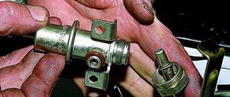
The regulator, responsible for maintaining normal fuel pressure in the system, is in direct interaction with the power unit. According to its location, it can be located in the fuel tank or in the rail (this is where you will be able to find the regulator if you have an injection VAZ-2115). The reason for the failure of this element is often the low quality of gasoline. If you fill up at gas stations with greatly reduced prices, then it is not surprising that very soon the regulator will fail.
The fuel flows through the injectors to the intake manifold, and it is important that its pressure does not change at this moment. The regulator measures the volume of fuel required for engine operation, and also monitors the pressure in the fuel rail and intake manifold.
The main task of the RTD is to maintain the pressure difference at the same level, as well as monitor the indicators.
Diagnostics of removed injectors
- Activate the battery by connecting the negative terminal.
- Connect the fuel supply pipe and power supply block to the removed ramp.
- Install the ramp in such a way that equal containers can be placed under each nozzle.
- An assistant is needed to turn the starter. The containers will be filled with fuel and poorly functioning injectors or those that are completely out of order will be revealed as the containers are filled.
- It is better to immediately replace a nozzle that is not working with a new one; washing the old one will not eliminate the problem for a long time. The same goes for sealing gaskets and power supply terminals.
- If the block is faulty, the injector will not function.
When diagnosing yourself, do not forget about fire safety!
Main symptoms of a malfunction
Problems with the regulator can manifest themselves in various ways:
- reduction in engine power (you can notice this when driving downhill or during acceleration);
- problems with starting the power plant (the starter rotates, but the engine does not start);
- Unstable engine operation at idle (you may often stall at intersections).
Even an inexperienced car user can notice these failures. It is important to diagnose your car in a timely manner so as not to spend money on fixing more serious breakdowns later. If you detect these signs in time, you will be able to carry out the repair yourself. Otherwise, you will have to evacuate the car to a service station.
WE RECOMMEND:
With the start of production of VAZ 2113, 2114 and 2115 cars, they used a carburetor-type engine with a volume of 1600 cubic centimeters. After long-term operation of this sample, several problems characteristic of the carburetor power system were identified. Namely: contamination of the jets, incorrect adjustment of the quality and quantity of fuel, unstable idle speed, etc. Therefore, it was decided to replace the type of power system with a more reliable one.
After the engineers chose which options to weed out and which to leave, the VAZ 2114 and 2115 with an injector engine were released. With the modification carried out, the engine design changed radically: power and speed increased, acceleration time to 100 km/h decreased. The engine size and number of valves remain the same. Let's look at what exactly the updated device contained, point by point.
When can fuel consumption increase?
It is worth paying special attention to such a sign of a regulator malfunction as increased fuel consumption.
The car will require more gasoline to operate if the valve in the regulator is faulty or, conversely, it does not hold fuel. In the first case, excess fuel is not returned to the tank; the car owner may notice a pressure above 2.5 kg/cm2. As a result, more gasoline enters the combustion chamber of the engine, which is not completely consumed. If the valve does not perform its functions, fuel “staggers” through the system. The pressure in the fuel system decreases, and as the speed increases, the engine feels a clear shortage of gasoline. The power unit becomes less responsive and powerful. A valve malfunction can be noticed when starting the car for a long time - during the process, the starter has to be turned for a long time until it creates the necessary pressure.
WHAT GASOLINE TO POUR IN THE VAZ-2114?
This topic has become overgrown with various conjectures and speculations, but we will try to put everything in its place.
The technical data sheet of the fourteenth indicates that the car engine requires AI-95 gasoline, and there is no reason not to trust the manufacturer’s recommendations.
Another thing is that many car owners, over their long driving experience, have accumulated rational doubts about the existence of any serious differences between 95 and 92 gasoline. Adding fuel to the fire was the recent statement by the chief engineer of the Moscow oil refinery, A. A. Abrosimov, that we do not make 95-grade gasoline in our country, and everything that is sold under its guise is either 92-grade or unknown fuel brought from somewhere.
As evidenced by reviews from VAZ 2114 owners who use exclusively 92-octane gasoline, there were no problems with the car during its service life due to fuel, and they see no point in using a more expensive analogue. However, the final decision about what to pour into the fourteenth is yours.
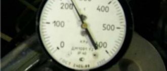
How to properly check RTD
In order to independently check the pressure in the system, and therefore the correct operation of the regulator, you need to take a pressure gauge, the maximum pressure in which is up to 10 atmospheres. You should not use a device with a larger scale, as its readings will have a serious error. It connects between the fitting and the fuel pipe:
- first turn off and cool the engine;
- locate the fuel rail under the hood;
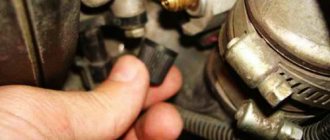
- remove the plug from the fuel pressure fitting;
- unscrew the fitting nipple using a spool valve;
- wipe the surfaces if fuel splashes appear under the influence of residual pressure;
- pull a hose with a diameter of up to 9 millimeters onto the fitting and secure it with a clamp;
- Connect the second hole of the hose to the pressure gauge.
Next, you will need an assistant, because the readings from the pressure gauge need to be read at one of four moments:
- when the ignition is turned on, the pressure should be 3 atmospheres;
- at idle speed - 2.5;
- when squeezing the fuel outflow hose - 7;
- with the hose removed on the RTD – 3.3.
If on your VAZ-2115 the measurements show different indicators, then you need to replace the regulator with a new one. To do this, it is enough to detect it in the system, dismantle it, and then return the fuel line to its original state. In the VAZ-2115, the engine of which has 8 valves or another system, the RTD is mounted at the very end of the fuel rail.
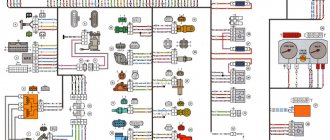
Electrical equipment
On a VAZ 2114 car, such a concept as: a unified circuit of electrical appliances is simply absent. This is explained by the fact that from 1999 to 2011, the injector was modernized, incorporating more and more new components into its device that affect the final power and speed of the machine. In order to study how the electrical wiring diagram and its components work, you need to understand this individually, together with a specialist. The basis of any such system is a computer. The rest of the device may differ radically from each other, depending on the year of manufacture of the VAZ car.
Description of the power system design
The vehicle's power system is designed to store fuel reserves, purify fuel and air from foreign impurities, and supply air and fuel to the engine cylinders.
The air entering the engine cylinders is cleaned of dust by an air filter. Air filter
installed in the engine compartment on three rubber supports. The filter element is replaceable and made of special paper. To prevent contaminated air from leaking into the intake tract, there is a sealing edging at the top of the element. To replace the filter element, the filter cover is removable. The purified air passes through the mass air flow sensor through the air duct to the throttle valve.
Throttle valve
regulates the amount of air entering the engine cylinders. The damper drive from the gas pedal is cable. The damper rotates on an axis in the housing (pipe). The throttle body is secured to the receiver flange with studs. The housing has a channel for coolant. The channel is connected to the cooling system by rubber hoses. Circulating coolant through the throttle body prevents the body's internal air cavities from freezing in the winter. The housing contains fittings for connection to the absorber and the engine crankcase ventilation system.
The throttle body, with the throttle position sensor and idle speed control installed on it, form the throttle assembly.
Throttle assembly:
1 - throttle valve drive sector; 2, 4 — fittings for connection to the engine cooling system; 3 — crankcase gas outlet fitting; 5 — throttle position sensor; 6 — idle speed regulator; 7 — fitting for connecting to the adsorber; 8 — throttle valve; 9 — throttle body pipe
Air is supplied to the intake valves of the engine cylinders through the receiver and the intake manifold.
Fuel tank
steel, welded from two stamped parts. The tank is suspended from the bottom of the car on two steel clamps. The filler neck of the fuel tank is located on the right side of the vehicle and is closed with a plug. Fuel from the tank is supplied by an electric submersible fuel pump.
The pump is installed in the fuel tank. To access the pump, there is a hatch with a cover in the bottom of the car under the rear seat cushion. A strainer is installed on the inlet pipe of the fuel pump, which traps small solid particles of debris that enter the fuel tank along with gasoline. The pump is turned on by command from the ECU.
Fuel pump:
1 — protrusion for fastening the mesh filter; 2 — fuel intake pipe for connecting a strainer; 3 - body; 4 — electrical connector block; 5 - outlet (discharge) pipe for connection to the fuel module cover with a corrugated tube
From the pump, through the corrugated tube of the fuel module (see below), gasoline enters the fuel line and then into the fuel filter, where the fuel undergoes more thorough cleaning.
The fuel filter is made of paper, installed in a non-separable metal housing. The purified fuel flows through the fuel line into the fuel rail.
Engine fuel filter 11183 (1.6i):
1 — inlet pipe; 2 - body; 3 — fuel flow direction arrow (painted on the filter housing); 4 - outlet pipe
Note. The fuel filter of the 2111 (1.5i) engine has threaded connecting pipes.
The fuel rail holds four injectors and supplies fuel to them. The connection between the ramp and the injectors is sealed with rubber rings.
The fuel pressure regulator is a bypass valve that maintains in the system (fuel line) the operating pressure necessary for proper operation of the injection system.
All cars of recent years of production are equipped with a fuel vapor recovery system (in accordance with EURO II environmental requirements), where the above-fuel space of the tank is connected to the atmosphere not directly, but through the elements of this system. The system consists of a separator, safety valve, adsorber, gravity valve, adsorber purge valve, check valve, connecting pipes and hoses. The separator and gravity valve are mounted under the right rear fender of the vehicle. In the separator, gasoline vapors are partially condensed and returned back to the fuel tank. The gravity valve prevents fuel from leaking out of the tank when the vehicle turns over. The safety (two-way) valve prevents the formation of excess pressure of fuel vapor in the tank, as well as the occurrence of vacuum there caused by fuel consumption.
Location of elements of the fuel vapor recovery system in the rear of the vehicle:
1 - safety valve; 2 - separator; 3 — plug of the filler neck of the fuel tank; 4 - gravity valve
Note. The photo shows the rear bumper.
From the separator, non-condensed gasoline vapors flow through tubes and connecting hoses into the adsorber, which prevents the vapors from entering the atmosphere. An adsorber is a container where gasoline vapors are absorbed by activated carbon. When the engine is running at high crankshaft speed, the ECU sends a signal to open the canister purge valve, and gasoline vapors are sucked into the intake module receiver.
Adsorber:
1 — adsorber body; 2 - pipe for connecting the internal cavity of the adsorber with the atmosphere; 3 — adsorber purge valve; 4 — valve connecting pipe; 5 — adsorber connecting pipe
Features of the 2111 (1.5i) engine power system
Location of elements of the 2111 (1.5i) engine power supply system in the engine compartment:
1 - receiver; 2 — vacuum supply hose to the fuel pressure regulator; 3 — throttle assembly; 4 - fuel rail; 5 — fuel pressure regulator; 6 — air supply hose to the throttle valve; 7 - adsorber; 8 — air filter; 9, 10 and 11 — hoses of the crankcase ventilation system; 12 — throttle valve drive cable; 13 — diagnostic fitting
Fuel pump
combined with the fuel level indicator sensor into a single unit -
a fuel module
(often called an electric fuel pump). The pressure pump delivers fuel from the tank through the fuel filter to the fuel rail.
Engine Fuel Module 2111 (1.5i):
1 — fuel level indicator sensor; 2 — connecting block; 3 — inlet pipe; 4 - outlet (discharge) pipe; 5 — module cover; 6 — module cover guide; 7 - electric fuel pump in a plastic casing; 8 - intake chamber
Fuel rail for engine 2111 (1.5i) complete with injectors:
1 — diagnostic fitting; 2 - fuel rail; 3 — fuel supply tube to the fuel rail; 4 — fuel pressure regulator; 5 — tube for draining (draining) fuel into the tank; 6, 7, 8 and 9 - injectors
Fuel pressure control
installed on the fuel rail. Excess fuel is returned to the tank through the fuel return line.
Engine power supply system diagram 2111 (1.5i):
1 - nozzle; 2 - fuel rail; 3 — diagnostic fitting; 4 - adsorber; 5 - check valve; 6 — throttle assembly; 7 - gravity valve; 8 — safety (two-way) valve; 9 - separator; 10 - filler pipe; 11 — fuel filter; 12 — fuel drain line; 13 — fuel line hose connecting the outlet pipe of the fuel module to the fuel filter; 14 — fuel module; 15 — fuel tank; 16 — fuel line connecting the fuel filter to the fuel rail; 17 - fuel pressure regulator
Features of the engine power system 11183 (1.6i)
Receiver
engine 11183 (1.6i) is made of plastic.
Engine Intake Module 11183 (1.6i):
1 — flange with an o-ring for fastening the throttle pipe; 2 - receiver with o-rings for connection to the inlet pipeline
Engine Fuel Module 11183 (1.6i):
1 — inlet pipe (for supplying fuel to the pressure regulator); 2 - outlet (discharge) pipe; 3 — module cover; 4 — fuel level indicator sensor; 5 - intake chamber; 6 — module cover guide
Fuel pump
combined with a fuel level indicator sensor and a fuel pressure regulator into a single unit -
a fuel module
(often called an electric fuel pump). Fuel from the pump (through the outlet pipe of the fuel module) enters the fuel filter. Purified gasoline is again supplied through the fuel line and through a tee to the inlet pipe of the fuel module, and then supplied to the fuel rail.
Engine fuel pressure regulator 11183 (1.6i):
1 — hole for dumping excess fuel; 2, 4 — sealing rings; 3 — holes for supplying fuel to the regulator; 5 — body; 6 - terminal for connecting the regulator to ground
Fuel rail for engine 11183 (1.6i) complete with injectors:
1 — diagnostic fitting; 2 - fuel rail; 3 — fitting for connecting to the fuel line; 4, 5, 6 and 7 - injectors
Excess fuel is released through the pressure regulator into the tank. The fuel pressure regulator is installed in the fuel module cover.
Engine power supply diagram 11183 (1.6i):
1 - nozzle; 2 - fuel rail; 3 — diagnostic fitting; 4 - adsorber; 5 - check valve; 6 — throttle assembly; 7 - gravity valve; 8 — safety (two-way) valve; 9 - separator; 10 — fuel line tubes connecting the fuel module to the fuel filter; 11 — fuel module; 12 — fuel filter; 13 - filler pipe; 14 — fuel tank; 15 — fuel line connecting the fuel module to the fuel rail; 16 — metal fuel pipe; 17 — connecting hose; 16 - fitting for connecting the fuel rail to the fuel line