Due to a malfunction of the ignition module, the following malfunctions may occur in the operation of the injection engine of VAZ 2108, 2109, 21099 cars: the engine “triples”, “doubles” (works or tries to start on two cylinders), unstable idling, “dips”, “jerks” , “twitching”, etc.
— Multimeter, autotester or other device with ohmmeter and voltmeter modes
— Socket wrenches or heads for “13” and “17”
Preparatory work
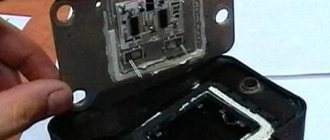
— Remove the ignition module from the engine
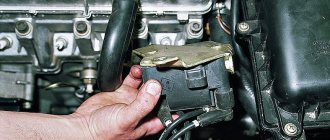
Disconnect the ends of the high-voltage wires. Use a key set to “13” to unscrew the two upper fastening bolts, and use a key set to “17” to loosen the tightening of the bottom bolt. Remove the module along with its bracket.
— Cleaning from pollution
Wipe with a dry cloth.
The procedure for checking the ignition module (coil) of the ignition system of VAZ 2108, 2109, 21099 cars with an injection engine
In garage conditions, you can check the secondary windings of the ignition module for an open circuit and the primary windings for a short circuit, as well as the voltage supply to the module from the ECU. This is quite enough to diagnose the problem.
— Check for short circuit
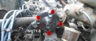
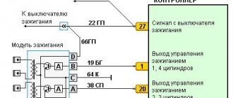
The positive probe of the multimeter in ohmmeter mode to terminal “D” of the ignition module connecting block, the negative probe to the bracket (“ground”). If there is no short circuit, the device readings tend to infinity.
— Check for “break”
Using a multimeter in ohmmeter mode, we alternately measure the resistance between terminals “1” and “4”, “2” and “3” of the ignition module.
The resistance for each measurement should be within 4 kOhm. If it is different or does not correspond to the required indicator, the module should be replaced.
— Checking the voltage supply to the ignition module
If previous checks did not reveal a malfunction, you need to check the voltage supply to the ignition module. Turn on the ignition. Using a multimeter in voltmeter mode, measure the voltage between terminals “C” and “D” of the block of the wiring harness going to the module (the terminals are marked on the block itself). The voltage must be within the vehicle's on-board voltage (12V). If it is smaller or absent, then the battery may be discharged, the wires from the computer to the ignition module are faulty, or the control unit (ECU) is faulty.
Notes and additions
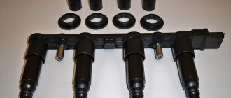
— Often, one of the visual signs of failure of the ignition module can be two wet and two working spark plugs, since the module consists of two pairwise connected ignition coils that alternately produce a spark in two cylinders -1-4, 2-3. The failure of one of the coils leads to the engine running (or trying to start) on two spark plugs.
— The problems listed above in the operation of a car engine may be based not only on a malfunction of the ignition module, but also on a malfunction of the spark plugs, high-voltage wires, as well as the power and control system (ECM).
More articles on the ignition system of the injection engine of VAZ 2108, 2109, 21099 cars
Comparative test repair
Dear drivers, one of the reasons for poor engine starting is a burnout in the ECU of the power key gb10nb37lz.
But for some reason, many car owners immediately think that their Crankshaft Position Sensor has failed, I once had this problem. But this was also due to the fact that the wire from the sensor lay on ground and when the engine heated up, the braid melted and a short circuit occurred. In my blog: www.drive2.ru/l/6251079/
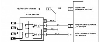
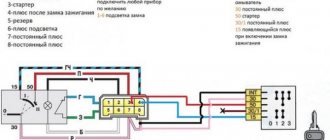
And so, our ignition diagram:
1 – battery 2 – ignition switch 3 – ignition relay 4 – spark plugs 5 – ignition module 6 – controller 7 – crankshaft position sensor 8 – master disk A – matching device
When the car does not start, most people immediately blame the crankshaft position sensor. Changing it they realize that it didn’t help. When checking the block, the wire does not give any result. The next steps are to install a new module, or this also does not give the computer anything. The car still won't start.
Everything is simple: the crankshaft sensor just has its own resistance, like the ignition module, by ringing it you can understand whether they are in good condition. Also don’t forget to check the fuse and main relay. Next, we check the spark plugs and armor wires to see if the retractor on the starter works (just put your hand on it, and if it doesn’t hit when starting, it means it’s working). During this check, you can understand what is wrong.
Checking the Crankshaft Position Sensor:
2. We quickly move the screwdriver blade close to the end of the sensor, while we observe voltage surges on the voltmeter.
Conclusion: The sensor is working.
Checking the DPKV circuit: With the ignition off, disconnect the engine management system wiring harness block from the crankshaft position sensor. We connect the tester probes to terminal “B” of the wiring harness block and engine ground.
Possible reasons for failure of the ignition module
Before repairing the main part in the car’s ignition system, you need to understand the nature of the problem. To do this, the consumer must be aware of the signs of a malfunction, as well as the causes of the breakdown.
The main reasons for device failure
Causes of problems:
- The ignition system uses spark plugs that do not match the vehicle parameters. They may not have the gap specified by the manufacturer. Also, the spark plugs themselves may not be working or dirty; this can be determined by visual diagnostics. If there are traces of carbon deposits on the devices, they must be removed.
- Malfunctions in the operation of the MH can arise as a result of frequent spark checks. At the time of diagnosis, a high load is placed on the device. If it appears frequently, it will lead to equipment failure or incorrect operation.
- The ignition module in the VAZ 2114 operates with the high-voltage cables disconnected. This also leads to device failure. The products themselves may be damaged, which affects the functioning of the engine as a whole.
- The device operates under severe vibration conditions. Their impact may be due to poor quality fixation of the module in the seat. As a result of vibrations, the factory soldering inside the equipment structure is damaged. This leads to its incorrect operation.
- The contact inside the plug with the low-voltage cables is broken.
- Initial use of a defective device or module with poor build quality. This factory defect can only be eliminated by replacing the mechanism; repairing the equipment is pointless.
- Moisture getting inside the case. This problem is unlikely, but exposure of the device to liquid may cause it to short out and break.
Signs of coil malfunction
The main symptoms of a malfunction in the VAZ 2114 ignition module:
- Difficulties arise when trying to start the engine. Starting the car engine may be difficult due to the fact that there is no spark on a spark plug or several.
- When idling or parking with the internal combustion engine running, the speed of the power unit floats. Their change is not associated with pressing the gas pedal and other third-party factors. This happens randomly.
- There are dips in the power of the car's engine. This is especially felt when driving uphill or sharp acceleration. Problems can also occur when driving on a flat road.
- Several cylinders stopped working. Usually these devices operate in pairs, so elements 1-4 or 2-3 could fail. Non-working cylinders may be indicated by “triple movement” of the engine.
- A “Check Engine” warning light appeared on the dashboard.
If the ignition module malfunctions, problems will appear not only in engine operation, but also when starting it.
The “Simple Opinion” channel, using the Lada Priora car as an example, spoke in detail about the symptoms that appear in the operation of the ignition modules.
How to check the malfunction of the VAZ 2114 ignition module on your own?
The easiest way to check the device without removing it is to diagnose it at the moment the power unit is tripped. When the motor begins to operate unstably, it is necessary to disconnect the connector elements from each component of the module one by one. If the connector is disconnected from a functioning device, the operation of the engine will change. Dips will appear, and the unstable operation of the unit will increase. When the non-working element of the MH is disconnected, the motor will operate in the same way.
There is another simple diagnostic method, its principle is as follows:
- You will need an assistant to check. The spark plug is removed from the seat. The high-voltage cable is disconnected from the device.
- Then the disconnected wire is connected to a spark plug, which is applied to the body of the power unit.
- The machine motor is starting, you need to make sure that a spark hits the spark plug. If it passes, a blue light will appear between the device and the surface of the power unit, its formation is accompanied by a crackling sound. If there is no spark, then the spark plugs, high-voltage cable and module must be diagnosed.
In the absence of special equipment, diagnostics of the MH can be performed using a control light indicator designed for 12 volts. One conductor from the lamp is connected to the pin of connector A, and the second is connected to ground for grounding. An assistant must start the power unit or rotate the starter mechanism. If the light flickers when performing these steps, then the device is working. Similar actions must be done with another contact.
The channel “Diary of an Auto Electrician” spoke about self-diagnosis of ignition modules, as well as other elements of the system.
Checking the ignition unit with a multimeter
Diagnostics is carried out in the following order:
- The car engine is started.
- The tester switch must be set to DC measurement mode, the limit should be up to tens of volts.
- One of the contacts of the multimeter is connected to connector D on the coil, and the other goes to ground. You can use a car body or a cylinder block as a mass. If there is power, the diagnostic tool display will show 12 volts.
- Then the tester switches to the ohmmeter operating mode, the range of values is up to tens of ohms.
- One contact of the diagnostic tool is connected to output C, and the second goes to ground. If the device is operational, the test will show a value of less than 1 Ohm.
- At the next stage, the tester must be switched to voltmeter mode. The range of values is up to tens of volts.
- One of the contacts goes to the output marked B, and the second is connected to ground.
- If the diagnostics show that the voltage is less than 0.3 volts, then the device is working. This indicates a clear signal passage from the Hall controller. Finally, you can perform a similar test, only with connector A. The results should be identical.
Setting up SZ
If you have a VAZ 2109 carburetor, you will have to adjust the ignition system from time to time. This procedure is not the simplest; it requires following clear instructions. The operating procedure is as follows:
- We take the manual for our “nine” in our hands, set the contact gaps in accordance with the recommended values. Typically this is 0.45 mm.
- The ignition timing is set using special equipment, we miss this point.
- We connect the high-voltage wires and begin adjusting the torque in the middle of the stroke.
- Install the spark plug in the first cylinder and turn on the ignition.
- Turn the pulley counterclockwise 45°.
- We connect the ground to the spark plug, turn the pulley gradually in a clockwise direction until a spark appears between the electrodes.
- We look at the marks of the cover and pulley. They must be on the same level.
- To ensure that the marks coincide, we turn the distributor in the desired direction.
- If the marks do not match, the ignition will either be late or turn on prematurely, which is unacceptable.
- We rotate the pulley and distributor until we get the desired result, after which the distributor will need to be tightened, and then turn the crankshaft two turns.
- Check the result: if everything works fine, we finish the adjustment.
- You need to warm up the engine, then drive at a speed of 40-50 km/h, switch to fourth gear and accelerate sharply. If there is a knock, the ignition worked prematurely, we adjust it again.
At the service station, technicians can also carry out the adjustment, so if you can’t do it yourself, go there.
For what malfunctions is it possible to repair the device?
Due to the fact that the ignition module by design includes a connection of two coils, it is difficult to repair. If there is a break or breakdown, as well as melting of the turns, the problem can be solved by replacing the device. This applies to any damage that appears inside the coils. The only option to correct the situation without replacing the device is to repair the damage to the solder joint.
Ignition module repair process
The repair procedure is carried out after preparing all tools and materials:
- a set of socket wrenches, you will need a tool for 10, 13 and 17;
- hexagon 5;
- flat head screwdriver;
- soldering iron with aluminum and flux;
- nail polish;
- multi-core conductors.
Restoring the ignition module operation is done as follows:
- The key is installed in the switch. The engine starts. Then you need to move the contact elements on the module to make sure they are not working.
- The power unit stops. The module is being removed.
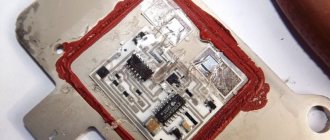
- The device body is cleaned from dust. To disassemble, you need to open the case; this is done by prying it off with a screwdriver. Inside the device there is a board on which there is a silicone film; you need to get rid of it.
- Aluminum is removed from high-voltage contact elements. Old wires are removed.
- The next step will be soldering new conductors to the circuit. To do this, the surface of the collector device is cleaned from traces of plaque. Then the board must be installed on an electric stove and heated to approximately 200 degrees. As the temperature increases, a slight burning smell may be heard. This is not a problem for the circuit; heating it will simplify the soldering procedure.
- Then soldering is done. Using a soldering iron, flux and aluminum, the ends of the conductors must be connected to the ignition module. All contact elements of the conductors that are connected to the circuit must be treated with nail polish.
- Then the device is assembled in the reverse order and installed in the seat. After installation, the power unit starts up. If the repair solves the problem, then using a sealant, the device is fixed in place.
- If a transistor or switching device fails, then these components cannot be repaired, but they can be replaced. To do this, the parts are removed from the board and replaced with new ones.
Ilya Balashov presented a video with the result of soldering the ignition module using the example of a VAZ 2110 car.
Replacing the ignition module of a VAZ 2114
If repairing the MZ VAZ 2114 is impractical or impossible, then the problem with the operation of the device can be solved by replacing it.
The equipment needs to be changed only when the battery is disconnected. Otherwise, there is a risk of short circuits and failure of other electrical appliances.
How to remove the ignition module of a VAZ 2114?
The dismantling procedure is performed as follows:
- First, the on-board network is de-energized; to do this, loosen the negative clamp on the battery with a wrench.
- Then a search for MH is performed in the engine compartment. You can find the device by four high-voltage wires that go from the spark plugs directly to the equipment. These cables are disconnected from the MH.
- Then the connector with conductors is disconnected from the device. It is necessary to disconnect the fixing fastener located on the ignition module housing.
- The MZ itself is secured to the bracket thanks to three nuts. You need to unscrew them using a key.
- After dismantling the fasteners, the device located on three studs is removed.
Connecting a new device
The equipment installation procedure is performed in reverse order; during installation, the following nuances must be taken into account:
- After installing the ignition module, you need to look at its surface. It is marked with numbers - 1, 2, 3 and 4. These symbols indicate the numbers of the cylinders to which the MZ should be connected.
- To properly connect the device, you need to look at the ends of the high-voltage cables. They are also marked with the same numbers. This is done in order to simplify the procedure for connecting the MH to the cables.
Connection diagram
The device must be connected in accordance with the diagram given in this section.
High voltage wires
Often, the main difficulty when repairing a carburetor VAZ 2109 is the reconnection of high-voltage wires that were previously disconnected from the distributor cover. It's also an ignition distributor.
The difficulty is that many people forget the connection procedure or simply do not know. But in practice, returning high-voltage wires is much easier than understanding the ignition module used on the injection VAZ 2109.
By following a few simple rules, you can easily return the wires to their rightful places.
- The ignition distributor cover is installed in its place, that is, on the distributor, only in a single position. Therefore, even if you wanted to, you won’t be able to confuse anything here. Otherwise the lid simply won't fit.
- There is an installation mark on the cover, which indicates the location of the wire socket from the first cylinder.
- The wires must be connected in the following sequence - 1, 3, 4, 2. Move counterclockwise when looking at the distributor cover from the side of the expansion tank.
What should I do if the problem remains after replacing the module?
If, after performing the repair, problems in the operation of the MH remain, then there is a possibility that the cause of the problem was not in the module. It is necessary to diagnose the remaining elements of the ignition system.
Spark plugs and ignition system
Features of checking spark plugs and other components:
- Before dismantling the devices, it is necessary to disconnect the ends of the high-voltage cables. Their condition is checked for damage. Defects in the tips often lead to malfunctions in the spark plugs. If there is damage, the wires are replaced. It is also necessary to assess the condition of the “high-voltage workers” themselves. They are not allowed to have any defects or damage to the insulation.
- After disconnecting the tips, the spark plugs are dismantled and a special spark plug wrench is used to unscrew them.
- After dismantling, the condition of the devices is assessed. The color of the parts must be brown; carbon deposits and soot on the electrodes are not allowed. If there are uncharacteristic marks, the devices are cleaned using a metal brush or fine-grained sandpaper. For a better effect, the electrodes of the candles can be heated on the stove.
- The condition of the gap between the part and the electrode element is checked. If it is too large, this indicates that the device is not working correctly. The spark plugs will need to be replaced.
Video “Visual guide to replacing MH”
The STO TONN channel presented a visual aid for replacing the ignition module on a domestic VAZ 2114 car.
Due to a malfunction of the ignition module, the following malfunctions may occur in the operation of the injection engine of VAZ 2108, 2109, 21099 cars: the engine “triples”, “doubles” (works or tries to start on two cylinders), unstable idling, “dips”, “jerks” , “twitching”, etc.
— Multimeter, autotester or other device with ohmmeter and voltmeter modes
— Socket wrenches or heads for “13” and “17”
Preparatory work
— Remove the ignition module from the engine
Disconnect the ends of the high-voltage wires. Use a key set to “13” to unscrew the two upper fastening bolts, and use a key set to “17” to loosen the tightening of the bottom bolt. Remove the module along with its bracket.
— Cleaning from pollution
Wipe with a dry cloth.
The procedure for checking the ignition module (coil) of the ignition system of VAZ 2108, 2109, 21099 cars with an injection engine
In garage conditions, you can check the secondary windings of the ignition module for an open circuit and the primary windings for a short circuit, as well as the voltage supply to the module from the ECU. This is quite enough to diagnose the problem.
— Check for short circuit
The positive probe of the multimeter in ohmmeter mode to terminal “D” of the ignition module connecting block, the negative probe to the bracket (“ground”). If there is no short circuit, the device readings tend to infinity.
— Check for “break”
Using a multimeter in ohmmeter mode, we alternately measure the resistance between terminals “1” and “4”, “2” and “3” of the ignition module.
The resistance for each measurement should be within 4 kOhm. If it is different or does not correspond to the required indicator, the module should be replaced.
— Checking the voltage supply to the ignition module
If previous checks did not reveal a malfunction, you need to check the voltage supply to the ignition module. Turn on the ignition. Using a multimeter in voltmeter mode, measure the voltage between terminals “C” and “D” of the block of the wiring harness going to the module (the terminals are marked on the block itself). The voltage must be within the vehicle's on-board voltage (12V). If it is smaller or absent, then the battery may be discharged, the wires from the computer to the ignition module are faulty, or the control unit (ECU) is faulty.
Notes and additions
— Often, one of the visual signs of failure of the ignition module can be two wet and two working spark plugs, since the module consists of two pairwise connected ignition coils that alternately produce a spark in two cylinders -1-4, 2-3. The failure of one of the coils leads to the engine running (or trying to start) on two spark plugs.
— The problems listed above in the operation of a car engine may be based not only on a malfunction of the ignition module, but also on a malfunction of the spark plugs, high-voltage wires, as well as the power and control system (ECM).
More articles on the ignition system of the injection engine of VAZ 2108, 2109, 21099 cars
Comparative test repair
The VAZ-2114 ignition module is also called a high-voltage coil, which serves to transmit current to the spark plugs. This module has its own signs of malfunction, by which it is necessary to determine when to replace the failed part. What are these signs? This will be discussed in this article.
How does the scheme work?
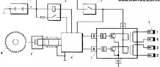
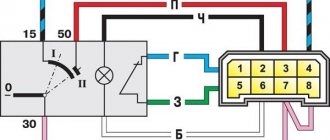
The contactless ignition system of the VAZ 2109 has a fairly simple operating principle, based on the sequential inclusion of various elements in the design. The electronic components of the circuit regulate the formation and supply of sparks to the working bodies. All this works according to the following principle:
- The rotation of the starter drives the camshaft, which in turn starts the distributor.
- The distributor contains a Hall sensor, near which there is a device with a hole. It serves to create a signal under the influence of a magnetic field.
- The electrical signal from the distributor goes to the switch.
- From the commutator, energy is supplied to a coil of two windings. There is a multiple increase in the charge, after which it goes to the ignition distributor.
- The current is distributed through the spark plugs, and the air-fuel mixture ignites.
To ensure proper spark distribution, the following occurs:
- A sensor located near the crankshaft transmits a signal to system monitoring devices.
- The controllers, in turn, process the received information and create the order in which current is supplied from the coils to the spark plugs.
- The coils create sparks - one to ignite the air-fuel mixture, the second to idle.
Return to contents
VAZ-2114 ignition module: various signs of malfunction
Experts note the main symptom of a faulty ignition coil is the absence of an igniting spark on the spark plugs. But, besides this, there are other signs by which one can judge that the module has failed:
- Lack of dynamics during engine acceleration.
- The appearance of failures in the operation of a car engine at the moment of sharply pressing the gas pedal with your foot so that the vehicle accelerates.
- A noticeable decrease in engine power (as they say, “the engine doesn’t pull”).
- “Swimming” of idle speed.
When the first signs of a malfunction of the described module appear, the owner of the VAZ-2114 should diagnose it. This can be done either independently at home or at the nearest service center for repairing cars of this model.
How to diagnose the ignition coil on a VAZ-2114
As already mentioned, when the first signs of malfunctions appear in the VAZ-2114 ignition module, the vehicle owner should diagnose it. You can perform a similar procedure yourself at home using the following algorithm:
- Check the spark plugs.
- Check the crankshaft position sensor.
- Check the ignition coil.
At home, all stages of the checks can be performed independently. The first stage is checking the spark plugs. It is carried out in the following sequence:
- We remove the spark plugs from their sockets - remove the tips of the high-voltage wires (a special spark plug wrench is suitable for this).
- We examine the candles.
- We clean them from possible soot.
- We set the correct distance between the electrodes.
- We check the spark plugs for operation using improvised means (for example, from a device made from a piezo lighter) or on a car engine with a working ignition system.
If the spark plugs are in good condition, you can proceed to the next stage of checking for faults in the ignition module.
The second step is to check the crankshaft sensor. This test is carried out using a multimeter, thanks to which two characteristics are checked - voltage and resistance. To do this proceed as follows:
- Remove the crankshaft sensor.
- Measure resistance:
- a special ohmmeter mode is installed on the device;
- the terminals of the device are connected to the ends of the winding, which is brought to the surface;
- with optimal sensor operation, digital readings will range from 500 Ohms to 700 Ohms.
- Measure voltage:
- switch the device to the mode for measuring alternating voltage;
- terminals are connected to the ends of the winding;
- any handy object made of metal should be passed along the body of the crankshaft sensor;
- When the sensor operates optimally, the device will show increased voltage readings because there will be a metal object nearby.
Otherwise, the faulty sensor will have to be replaced with a new one, because it also affects the operation of the VAZ-2114 ignition module. If after this there are still signs of coil malfunction, then you should proceed to the third stage of the test.
The third stage is checking the ignition coil itself. This part is checked as follows:
- The easiest way is to replace the coil with a new one;
- while the car engine is running, you can move the coil and knock on it (if there are visible changes in the functioning, it is time to judge a faulty contact in the coil itself);
- take measurements with a multimeter for resistance readings, such indicators are taken from paired coils - they should be identical, approximately equal to 5.4 kOhm.
What to do if you don’t have a multimeter, but you need to check the electrical circuit? Experts recommend using a twelve-volt light bulb. To do this, one of the wires coming from it should be connected to the terminal, and the second wire should be shorted to the motor housing. If the control light flickers when the starter starts, then everything is in working order.
If the car owner has problems performing such diagnostics himself, he can always turn to qualified specialists at a service station.
Design features
It is possible to understand how the ignition module works only using the example of the entire system. So, it includes the following components:
- Ignition coil in a VAZ 2109 car injector. There are always two coils and this is the very mechanism that generates the current.
- High-voltage key switches, there are also two of them, through them the current goes to the spark plugs, in addition, the controller regulates how long the current will be turned on, it calculates the required time based on the data received from the crankshaft sensor.
- Electronic control unit.
- The body of the device itself is made of durable plastic.
In addition, the following elements can be distinguished in the electronic ignition system:
- Crankshaft position sensor.
- High voltage wires.
- Pulley with ring gear.
- Controller.
- Spark plugs that produce sparks.
We will not dwell on these components in more detail and will discuss the principle of operation of the ignition module itself.
Module location
Those who are not very familiar with the structure of the car should know that the device is located in the engine compartment of the car. It's very easy to find. First of all, find the high-voltage wires. One end of them approaches the spark plugs, and the other comes directly from the desired device. The device itself is not very large and is enclosed in a plastic case.
Methods for preventing the ignition module on a VAZ-2114
Malfunctions of automobile ignition coils on the VAZ-2114 can be avoided if preventive procedures are regularly carried out. These include:
- Periodic unraveling of high-voltage wires (associated with greatly increased internal resistance, as this can damage the module).
- Checking the spark gap between the electrodes of the spark plugs (if the distance between the electrodes changes, this will affect the efficient operation of the ignition coils).
If faulty spark plugs are identified, they are replaced, after which the car will function properly again.
Features of the operation of different ignition systems
Ignition on the VAZ 2109 is necessary to ignite the air-fuel mixture when starting the engine. If the ignition does not work correctly, the engine will start and run intermittently, and its power during start-up and acceleration will noticeably decrease. In addition, fuel consumption will be noticeably increased. The conclusion from this is that the correct operation of the ignition system should be constantly monitored.
It’s worth mentioning right away the differences in the ignition design of “nines” with different types of fuel supply. Their SZ is similar, but they differ in the elements of electric charge distribution.
- In “nines” equipped with a carburetor, there is a coil and a distributor.
- For systems with an injector, an ignition distribution module consisting of several coils and an electronic controller is installed.
The second difference is how the system works. In cars with an injector it is not required, but in VAZs with a carburetor you have to do it manually.
In nines, two types of ignition systems are used:
- contact;
- contactless with transistors.
The first is installed in carburetor “nines”, and the second in injection ones. Thanks to the use of contactless ignition, the system has the following advantages:
- Working with a Hall sensor, which makes the system more stable and increases its overall efficiency.
- The absence of contact with the working parts and elements of the system increases the service life of the elements and makes maintenance of the circuit components easier.
- Excellent spark distribution between spark plugs.
- Generating a powerful spark, which prevents system failures.
- Fuel economy.
- Works even with low battery charge.
Over time, the contact type SZ has practically ceased to be used, so from now on we will focus on the contactless analogue.