Pinout, connection diagram and check of the VAZ ignition coil
Today we will look at the design and diagrams of ignition systems for VAZ cars of all major models. Since carburetor versions of VAZ are practically history, we will dwell in detail on the ignition systems of injection cars. Their ignition system is based on an electronic ignition module. We also recommend that you carefully consider the choice of spark plugs and the quality of high-voltage wires, because the quality of the spark and, accordingly, the operation of the ignition system as a whole will depend on them. The information is intended as a reference guide for self-repairing a car.
What does the VAZ 2109 ignition system consist of?
A centrifugal and vacuum actan corrector is used to adjust the ignition timing in the distributor. The switch is connected to the ignition system of the VAZ 2109, and the switch controls the generation of a spark by the ignition coil based on the received signals. The oil-filled ignition coil type 8352.12 with an open magnetic circuit has three terminals: central high-voltage, “K” and “B”. Terminal “B” is connected to the positive AB via the ignition switch.
Through the switch, the terminals of the primary and secondary windings of the ignition coil and the minus of the battery are connected to terminal “K”. The second end of the secondary coil and the high voltage wire is attached to the high voltage terminal.
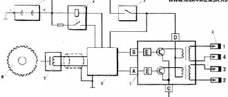
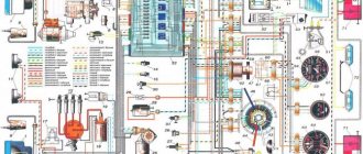
The photo shows the ignition circuit of the VAZ-2109
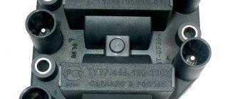
Pinout and diagram of the VAZ ignition coil
Pinout of ignition coil modules for various car models of the VAZ family:
Ignition VAZ 2101
1 – generator; 2 – ignition switch; 3 – ignition distributor; 4 – breaker cam; 5 – spark plugs; 6 – ignition coil; 7 – battery.
Ignition VAZ 2106
1 – ignition switch; 2 – fuse and relay block; 3 – EPHH control unit; 4 – generator; 5 – solenoid valve; 6 – microswitch; 7 – spark plugs; 8 – ignition distributor; 9 – ignition coil; 10 – battery.
Ignition VAZ 2108, 2109
Ignition VAZ 2110
Ignition VAZ 2111
Ignition VAZ 2112
Ignition VAZ 2114
Diagram of a non-contact ignition system: 1 – non-contact sensor; 2 – ignition distributor sensor; 3 – spark plugs; 4 – switch; 5 – ignition coil; 6 – mounting block; 7 – ignition relay; 8 – ignition switch.
How to check the ignition coil of a VAZ
If the ignition coil is faulty, the engine will not start. A characteristic sign of a faulty coil is its increased temperature when the ignition is turned off. This is easy to determine by touch.
Signs of a faulty ignition module may include the following:
- hesitant engine starting or failure to start;
- failures during sudden changes in speed;
- high fuel consumption;
- two cylinders do not work, the engine is feverish;
- lack of dynamics;
- a sharp drop in power;
- drop in power and thrust after warming up.
These symptoms may not only be caused by the ignition module. To determine the malfunction, it is enough to spend a few minutes diagnosing spark plugs, high-voltage wires and caps. This will eliminate the remaining elements of the ignition system and make sure that it is the ignition module that is faulty.
Checking the ignition coil is performed in one of 2 ways. The simplest one is to remove the central wire from the breaker-distributor, bring it to the motor housing and turn it with the starter, and a running spark should appear. After this, we check the energy supply to a separate spark plug, for which we unscrew the working spark plug, bring its contact to ground and attempt to start the engine. In this case, the spark should come from the wire to ground. If it is absent, the reason will be a malfunction of a system element such as the ignition coil.
To check the module in the second way, we only need a multimeter, then follow the step-by-step instructions:
- We check the power supply and the presence of pulses supplied from the ECU. We check the power between the central terminal (15) of the wire block connected to the module and the engine ground. When the ignition is on, the voltage should not be less than 12 V. Otherwise, either the battery is dead or the ECU does not work.
- We check the pulses from the ECU on the wiring block. We install one tester probe on connector 15, the second on the far right, then on the far left. The assistant cranks the engine with the starter, and at this time we record short-term voltage surges with a tester. If there are no impulses from the ECU, it is he who is to blame.
- We check the resistance on the secondary windings of the coils. We put the tester in resistance measurement mode and measure it at the high-voltage terminals of the module cover. Between pins 1 and 4 and pins 2-3, the resistance should be 5.4 kOhm. Otherwise, the module must be replaced.
- We check the resistance of the primary windings between contacts 15 and the rightmost, then the leftmost terminals. Nominal - 0.5 Ohm. Deviation is not allowed.
- Check the module for a short circuit. In ohmmeter mode, install one multimeter probe on the central terminal, the second on the metal body. There shouldn't be any resistance. If the device detects at least some resistance (other than unity or infinity), the module must be replaced.
Ignition coil device for VAZ 2108
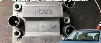
Ignition coils for each individual car model have their own nuances. On VAZs it is placed in the engine compartment, right under the hood. Externally, it is a metal cylinder (also called a bobbin), inside of which a simple system is hidden: a transformer with a steel core inside, located between two windings. The bobbin itself is secured to the left side of the mudguard using long pins.
Separately, it is worth mentioning the winding. On VAZs, the initial voltage supplied to the ignition coil is only 12 volts. Initially, the primary winding is turned on (looks like a copper wire with 130-140 turns). The secondary winding is superimposed on top of the first and is more solidly constructed - it is thinner copper wiring, in which up to 25 thousand turns can be counted.
Note that the connection diagram on VAZs is one of the most complex when compared with other cars. But this, in many ways, guarantees the reliability and good performance of VAZs.
Connecting and replacing VAZ short circuit
The procedure for removing and installing the ignition coil on old VAZ models:
- First, disconnect the central high-voltage wire leading to the distributor (ignition distributor).
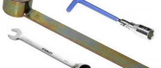
- Disconnect all power wires from the coil contacts. Since they are fastened with nuts, you will need an 8 wrench for this.
- If you don’t know which wires to connect to which connector later, it’s better to immediately remember or mark them somehow, so that later during installation you can connect them correctly.
- Unscrew the coil housing. It is attached to a clamp (clamp), which is pressed to the car body with two nuts.
- After the work has been done, you can remove the ignition coil and replace it if necessary.
For new type VAZ cars:
- We remove the “minus terminal” from the battery.
- Remove the top protective cover of the engine. If the engine volume is 1.5 liters, then this part is missing and this step is skipped.
- We remove the high-voltage wires from the coil.
- Now, using a 13mm wrench, unscrew the two fasteners.
- Using a 17mm wrench, loosen one bolt securing the coil.
- We take out the module.
- Use a hexagon to unscrew the coil from the holder.
- Assembly is carried out in reverse order.
Particular attention should be paid to the connection, since high-voltage wires must be located in the strict order provided for by the design. If this is not done, the car will stall or the engine may not start at all.
Replacing the ignition coil on a VAZ is quite simple. Even a novice motorist can do this in his garage, and if everything seems too complicated, contact a car service center. Particular attention should be paid to the choice of product, since this will determine how well the engine and ignition system will work.
Video on repairing KZ VAZ
About the most important thing! The ignition system in cars of the Samara family is non-contact, and it consists of:
Ignition distributor, also known as distributor:
1. First, let's look at what is included in the main composition of the distributor. Firstly, it includes a hall sensor, and secondly, a centrifugal and vacuum ignition timing regulator, and much more.
2. Previously, on all cars equipped with a 21081 engine, the ignition distributor was installed of the “40.3706-10” type, which had completely different characteristics of the vacuum and centrifugal ignition timing regulator. And also the cover of such a distributor was marked with a red mark.
3. The ignition distributor is needed to perform two main functions:
- The first function it performs is to set the moment of spark formation, which is carried out depending on the car’s engine speed.
- Its next function is that at the right moment it gives a high voltage pulse, in other words, a spark into the cylinders, depending on the order of their operation.
Note! The ignition distributor supplies a spark to the cylinder using a slider that is installed in the distributor itself, and it is put on the distributor shaft there!
Spark plug:
1. Many people already know why there are spark plugs in a car, but let’s take a closer look.
2. Every gasoline car needs spark plugs, and their job is that with their help, fuel particles in the cylinders burn out in a timely manner, due to the fact that the spark plug gives a spark at the right moment, but where does the spark come from for this spark plug? Yes, everything comes from the same ignition coil, with whose help the car’s engine runs.
3. Spark plugs in cars of the Samara family are used according to the type “A17DVR” as well as “A17DVRM” and “A17DVRM1”. There are other foreign analogues, but these are essentially the most common spark plugs used in these cars.
4. Sometimes there comes a time when the spark plugs, so to speak, become obsolete, and therefore they need to be periodically every 30,000 km. replace with new ones. If you still have to replace them, then we have prepared an article for you in which you will find detailed instructions on how to replace them. (see Replacing spark plugs)
Ignition coil:
1. The coil, as it is popularly called, performs the function of converting a low voltage current into a high voltage current, below we will analyze all this in detail.
2. First, understand once and for all that the ignition coil is essentially an element that works due to the battery, and several other factors. The principle of operation of the coil is as follows:
Switch:
1. It is a kind of small module, due to which the following is carried out:
- Current stabilization, that is, in other words, the switch prevents the current from falling below “6 Volts”, and it also prevents the conversion of current above “18 Volts”. Thanks to these actions, the wires of the contactless ignition system burn out much less often.
- It also creates current pulses in the ignition coil.
- It also protects parts from overheating and overload, so they will last a longer life.
- And in addition to all this, the switch de-energizes the ignition in the car at the moment when you turn off the car engine.
2. On cars of the Samara family, switches of the type “3620.3734”, as well as “76.3734” are installed; switches of the type “RT1903” and “PZE4022” are also subject to installation.
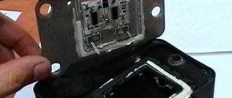
3. If the switch fails, it cannot be repaired. If you begin to notice that the switch is becoming unusable, it is recommended to replace it with a new one.
4. It is forbidden to disconnect the block of wires that is connected to the switch when the car’s ignition is on, because this can damage it, and damage to other parts of the ignition system may also occur.
Ignition switch:
1. The switch is a lock, which you have all already seen in every car. Thanks to this switch, you can turn on and off the ignition system devices.
2. The switch includes an individually selected key with which we can turn this switch. And in the switch body there is a fixed disk with terminals and contacts, and the wires that come from the ignition coil are connected to this disk.
3. When the key is removed from the lock, all contacts subsequently open. And when the key is inserted into the cylinder and then turned, in this case all contacts are closed, and therefore the ignition in the car is turned on.
4. In cars of the Samara family, an ignition switch of the type: “2108-3704005” and “KZ813” is used, which includes an anti-theft locking device. When you turn the key in such a switch, voltage is first supplied to an additional relay of the “113.3747-10” type, which then supplies voltage to the ignition coil and switch.
VAZ models 8 and 16 valves
Despite the similarity in engine design, the ignition system of the 1.5-liter injection 16-valve engine differs from the 1.6 16-valve engine. The 1.6 liter engine uses an electronic contactless ignition system with individual coils on each spark plug. Therefore, there was no need for an ignition module. Such a system is more reliable and cheaper to operate, since if one coil fails, there is no need to replace the entire module.
The 16-valve 1.5-liter VAZ 2112 injection engine used the same non-contact ignition system as the 8-valve engine, but a different ignition module was installed. Its catalog number is 2112-3705010. The design of the module remains the same - two ignition coils (for cylinders 1-4 and 2-3) plus switch keys in a single block. The spark is supplied to the cylinders in pairs using the idle spark method. This means that sparking occurs in two cylinders simultaneously - in one on the compression stroke (working spark), in the second on the exhaust stroke (idle spark).
Examination
If you notice signs of a problem with the ignition coil, or have to deal with a situation where the engine “died,” be sure to check the condition of this element.
As you test, you will be able to determine what caused the coil to fail and how the problems can be corrected.
How to check the device? The instructions are not complicated, even a beginner can handle it.
First, let's check the condition of the unit, and then check for correctness of the resistance of the coil itself.
- If the engine cannot be started, make sure that the coil itself is producing a spark at all. To do this, the central wire is removed from the distributor and a spare spark plug is connected to it.
- Now take the spark plug with pliers and place the metal casing on the breaker or motor.
- If a spark does not appear when the engine starter is turned, there is a malfunction in the ignition system.
- So check the power to the coil, or rather its presence. For this you will need a multimeter. One terminal is connected to contact B on the coil, and the second goes to ground. Turn on the ignition. If there is no voltage, the culprit is the ignition switch.
- You can start the engine in emergency mode. To do this, the plus from the battery is thrown onto contact B of the coil.
If there is voltage but there is no spark, check whether the primary winding is intact. To do this, the side low-voltage wires are disconnected from the coil and resistance measurements are taken with a multimeter. Then the secondary winding is checked.
We will tell you about this procedure in more detail.
Multimeter for testing
Checking coil resistance
- Unplug your car. To do this, simply disconnect the negative terminal from the battery.
- Disconnect all wires and leads going to and from the coil.
- Be sure to arm yourself with the necessary tools and a tester. A universal multimeter or ohmmeter will work fine.
- Take measurements on the primary winding. To do this, the tester probes must be connected to the low-voltage terminals located at the edges of the coil. Before doing this, do not forget to clean the terminals from accumulated dirt and traces of oxidation. Surely they formed during the operation of the car.
- Record the data.
- Now the resistance of the secondary winding is checked. To do this, you need to transfer one ohmmeter probe to terminal B of the coil, and the second to the high voltage.
- Note your results.
- The last stage of the test involves measuring the insulation resistance to ground. To do this, you need to connect one terminal of your tester to ground (this is the ignition coil housing), and connect the second one in turn to all three terminals - a pair of low-voltage terminals and one high-voltage one located in the middle of the device. If the coil is working properly, then in all three measurement cases you will get a resistance of at least 50 ohms.
- Check the table against the previously recorded data.
[media= https://www.youtube.com/watch?v=2F4BDExybgs]
| Coil type | Winding | Resistance indicators |
| 3122.3705 | Primary winding | 0.43 ohms +/- 0.04 ohms |
| 8352.12 | 0.42 ohm +/- 0.05 ohm | |
| 3122.3705 | Secondary winding | 4.08 ohms +/- 0.40 ohms |
| 8352.12 | 5.00 ohms +/- 1.00 ohms |
The procedure for connecting high-voltage wires on a VAZ 2109 (carburetor, injector)
The ignition module on injection VAZ 2109 is deservedly considered one of the most complex electrical components. If the injectors have a module, then the carburetors have the simplest coil.
The actual, but incredibly important task of the module is the generation of high voltage current, which can reach 30 thousand watts. The current follows high-voltage wires to the spark plugs, which create a spark to ignite the air-fuel mixture.
The classic ignition coil is one of the components of the module, so the system works on a much more complex principle than on carburetors.
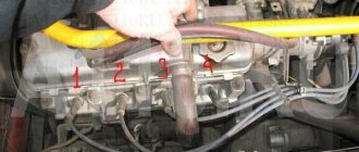
High voltage wires
Often, the main difficulty when repairing a carburetor VAZ 2109 is the reconnection of high-voltage wires that were previously disconnected from the distributor cover. It's also an ignition distributor.
The difficulty is that many people forget the connection procedure or simply do not know. But in practice, returning high-voltage wires is much easier than understanding the ignition module used on the injection VAZ 2109.
By following a few simple rules, you can easily return the wires to their rightful places.
- The ignition distributor cover is installed in its place, that is, on the distributor, only in a single position. Therefore, even if you wanted to, you won’t be able to confuse anything here. Otherwise the lid simply won't fit.
- There is an installation mark on the cover, which indicates the location of the wire socket from the first cylinder.
- The wires must be connected in the following sequence - 1, 3, 4, 2. Move counterclockwise when looking at the distributor cover from the side of the expansion tank.
If for some reason there are no installation marks on the VAZ 2109 carburetor distributor cover, just follow the connection principle shown in the image.
Features of the ignition module
Now let's talk about a more complex issue - the ignition module and its design features.
The design includes several components, each of which has its own nuances.
Peculiarities
There are always two coils on a VAZ 2109. This mechanism is responsible for generating current
Switch keys also work together. Through them, the current goes to the spark plugs, plus the controller regulates the time the current is turned on, which is calculated by receiving information from the crankshaft sensor
Electronic control unit
Responsible for distributing information in the form of electronic impulses
High-strength plastic is used for its manufacture, which largely ensures the durability and reliability of the device.
Ignition coil
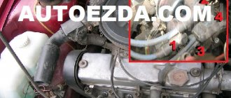
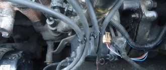
Location
Any work related to repair, testing, and maintenance of the ignition module will be impossible to perform if you do not know basic things - the location of the device.