One of the important elements of the ignition system necessary for igniting the working combustible mixture in the internal combustion engine of a car is the ignition module (ignition coil). The VAZ 2110 ignition coil converts low-voltage voltage into high-voltage, which creates a spark on the spark plugs.
It is quite obvious that if a malfunction occurs in the ignition, first of all the spark plugs, wires, caps, and then the ignition coil itself are checked for functionality.
In other words, you need to know how to test module 2110 (ignition coil). Next, we will look in more detail at what it is and how to check the ignition module, what malfunctions occur and how to fix them.
We check the ignition module on the injection VAZ-2110 8 valves with our own hands
At different times, different engines were installed on the VAZ-2110 car, both carburetor and injection. However, regardless of the type of power system and the number of valves (8 or 16), all engines are assembled on the unit base of the old engine 21083 and 21093. The most progressive of these engines is the 16-valve 1.6-liter VAZ 21124 engine with a power of 89 horsepower. Today we will touch on the ignition module for 8-valve engines 2111 and 21114 (1.6 l), check its performance and find a suitable replacement for the failed module.
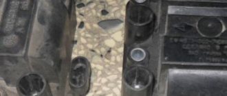
Design
Disassembled module
Structurally, the ignition module includes two main elements:
- 2 ignition coils that generate high-voltage pulses directed to the spark plugs;
- Dual channel switch.
The reasons for failure can be different, ranging from interruptions in the operation of the engine, ending with an unexpected stop of the power unit. Please note that the "Check Engine" light does not turn on.
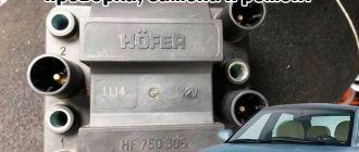
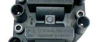
Version of the module on the 8-valve VAZ-2110
Ignition module 2111-3705010 (Stary Oskol).
Ignition module 2112-3705010 for a one and a half liter engine.
The top ten was equipped with two 8-valve engines of different sizes - 1.5 (2111) and 1.6 liters (21114). The ignition modules for these engines are different.
- The one and a half liter engine has a module with article number 2112-3705010,
- and the 1600 cc engine is equipped with module 2111-3705010.
A module for a 1.5 liter engine costs about 1500-2100, and the second one is 500 rubles cheaper.
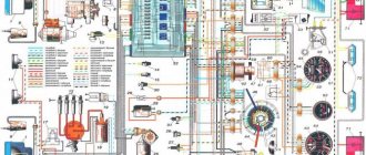
Contactless engine ignition system 2110
Diagram of a contactless ignition system.
The contactless ignition system consists of an ignition distribution sensor 2, a switch 4, an ignition coil 1, spark plugs 3, an ignition switch 5 and high voltage wires. The power supply circuit for the primary winding of the ignition coil is interrupted by an electronic switch. Control pulses are supplied to the switch from a contactless sensor (Hall sensor) located in the ignition distributor sensor.
Ignition distributor sensor - type 40.3706 or 40.3706–01, four-spark, unshielded, with vacuum and centrifugal ignition timing regulators, with a built-in microelectronic control pulse sensor (Hall sensor).
Switch – type 3620.3734, or 76.3734, or RT1903, or PZE4022. It converts the sensor control pulses into current pulses in the primary winding of the ignition coil.
Ignition coil - type 3122.3705 with a closed magnetic circuit, dry or type 8352.12 - oil-filled, sealed with an open magnetic circuit. Spark plugs - type A17DVR, or A17DVRM, or A17DVRM1, or FE65PR, or FE65CPR with noise suppression resistors.
Ignition switch - type 2110–3704005 or KZ–881 with an anti-theft locking device, with a lock against re-starting the starter without first turning off the ignition and with an illuminated socket.
The ignition system of the 2110 engine is an injector.
The VAZ 2110 injection engine control system is a group of complex electronic and mechanical devices that require certain knowledge and approaches to repair. It consists of a set of sensors, actuators and a central control unit - the controller.
Location of elements of the injection engine control system 2111
- mass air flow sensor;
- coolant temperature sensor;
- knock sensor;
- adsorber for gasoline vapor recovery system;
- crankshaft position sensor;
- throttle pipe (it contains a throttle position sensor and an idle speed regulator);
- speed sensor (located on the gearbox);
Which is better?
SOATE devices manufactured in Stary Oskol have proven themselves to be the most reliable ignition modules.
Module structure
The module consists of two ignition coils and two high-voltage switch switches.
Inside the module there is a board with radio components and ignition coils filled with compound.
The coil generates a high voltage pulse, and it is a simple transformer with two windings, primary (induction voltage about 500 V) and secondary (induction voltage at least 20 kV). All this is assembled in a single housing, on which there is a connector for signal wires (from the engine control unit) and four terminals for high-voltage wires.
Schematic diagram of the module.
The module operates on the principle of an idle spark - it distributes sparks in pairs to cylinders 1-4 and 2-3 according to impulses transmitted from the ECU.
Pinout and diagram of the VAZ ignition coil
Pinout of ignition coil modules for various car models of the VAZ family:
Ignition VAZ 2101
1 – generator; 2 – ignition switch; 3 – ignition distributor; 4 – breaker cam; 5 – spark plugs; 6 – ignition coil; 7 – battery.
Ignition VAZ 2106
1 – ignition switch; 2 – fuse and relay block; 3 – EPHH control unit; 4 – generator; 5 – solenoid valve; 6 – microswitch; 7 – spark plugs; 8 – ignition distributor; 9 – ignition coil; 10 – battery.
Ignition VAZ 2108, 2109
Ignition VAZ 2110
Ignition VAZ 2111
Ignition VAZ 2112
Ignition VAZ 2114
Diagram of a non-contact ignition system: 1 – non-contact sensor; 2 – ignition distributor sensor; 3 – spark plugs; 4 – switch; 5 – ignition coil; 6 – mounting block; 7 – ignition relay; 8 – ignition switch.
Signs
- If one of the module coils completely fails, then two cylinders do not work. This is clearly visible even to the naked eye - the engine is feverish at idle, starting is difficult, fuel consumption is sky-high, loss of dynamics.
- To eliminate all other components of the ignition system, make sure that the spark plugs are in working order. To do this, unscrew them and check the spark on each of the spark plugs by cranking the engine with the starter and placing the spark plug with the high-voltage wire on the head so that the body (threaded part) of the spark plug touches the engine mass. If there is no spark or it is weak, replace the spark plug with one that is known to work.
- If this does not lead to anything, check the high-voltage wires. Thus, we will exclude spark plugs, caps and high-voltage wires from the list of non-working elements. Next we will check the ignition module.
Breakdown of the spark plug insulator.
Dirty spark plug electrodes.
Filled candles.
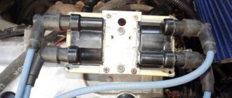
Removing the EPHH carburetor control unit and ignition system switch
Disconnect the negative cable from the battery.
Using a Phillips screwdriver, unscrew the two self-tapping screws securing the right flap of the floor tunnel lining and remove the flap.
Disconnect the connector of the EPHH control unit
Using a size 8 wrench, unscrew the two nuts securing the block to the bracket and remove the block
In the same way, by removing the left flap of the floor tunnel lining, we disconnect the ignition system switch from the bracket.
Testing the switch
Disconnect the brown wire with a red stripe from terminal “K” of the ignition coil (the wire goes to contact “1” of the switch).
Connect this wire to a 12V, 3W test light.
Connect the other contact of the lamp to terminal “K” of the ignition coil
Crank the engine with the starter, and the lamp should flash.
If the lamp does not light up, replace the switch.
This test method allows you to check whether the switch supplies control pulses to the ignition coil.
A more accurate check (the duration and shape of the pulses) of the switch must be carried out on a special stand.
Source
How to check the ignition module?
- First of all, we carefully inspect the module body. There should be no chips, burns or cracks on its surface. A module with a damaged casing is replaced without any hassle.
- If the spark is unstable only on cylinders 1-4 or 2-3, one of the module coils is probably damaged. In any case, we will conduct a comprehensive check of the device. For this we will need a regular multimeter.
Multimeter for checking the ignition module.
Lada Samara, 2113-2115
On carburetor models of VAZ cars of the Samara family (2113-2115), ignition coils 2111.3705 (analogous to Bosch F000 ZS0 211) are installed. These coils have a 3-pin connector and are used for VAZ cars with a microprocessor internal combustion engine control system based on the M7.9.7 controller or its analogues with 8-cl. engines.
Diagnostic procedure
The diagnostic procedure can be as follows:
- Disconnect the connector with signal wires from the module.
Remove the connector from the module by moving the lock slightly and pulling the wire.
- Turn on the ignition and check the voltage at terminal 15 (central) of the control wire block. The rated voltage is 12 V. A drop or absence of voltage when the battery is charged indicates that the engine control unit does not supply power to the module. This means the reason lies in the ECU.
We check the voltage between pin 15 and the block ground.
- We remove the high-voltage wires, unscrew the module mounting bots and remove it.
Using a 13mm wrench, unscrew the bolts attaching to the cylinder block.
Unscrew the bolts securing the clutch housing.
Remove the module along with the bracket.
- We check the resistance of the primary windings of the coils - put the multimeter in resistance measurement mode and take readings from the rightmost and central terminals, then from the leftmost and central terminals. The nominal resistance of the primary windings is approximately 0.5 Ohm.
Scheme for checking the primary windings.
We measure the resistance of the secondary windings between terminals 1-4 and 2-3 high-voltage wires. Nominal value: 5.4 kOhm. If the readings do not correspond to the nominal value, the coil is not working correctly.
Scheme for checking secondary windings.
Check the module for a short circuit. To do this, install one tester probe on the central pin 15, the second on the metal body. The device should show the absence of a short circuit (one or infinity). Otherwise, one of the coils has shorted to the housing.
Scheme for checking the module for short circuit.
Replacement
Replacement is quite simple and effortless. To replace, you will need a ratchet with an extension and a 10mm socket.
Replacement process
- We remove the negative mark from the battery, since the work is carried out on the electrical equipment of the car. This will avoid an unintentional short circuit in the vehicle's network.
- We remove the high-voltage wires from the MZ and the power connector.
- We unscrew the nuts securing the MZ and dismantle it.
Pay attention to the order in which the wires are connected. Do not confuse them, otherwise the car engine will not start. Cylinder numbering starts from the timing mechanism from left to right. Connect the wires as it is written on the Ministry of Health.
Source
Errors
A module malfunction can also be determined using an error scanner. Error codes associated with the module are:
- R-3000, R-3001, R-3002, R-3003 and R-3004 - gaps in sparking, the module itself, spark plugs, high-voltage wires or the ECU may be to blame;
- R-0351 - the coil of cylinders 1-4 does not work;
- R-0352 - the coil of 2-3 cylinders does not work.
The scanner readings do not yet indicate problems with the module itself.
It is possible that the spark plugs are not working or the high-voltage wires are broken, but if we initially diagnosed them, then the fault lies entirely with the ignition module. In this case, we can repair it ourselves, or buy a new one, which is faster, easier and guarantees uninterrupted operation of the ignition system. Good luck to everyone, strong spark and good roads!
Repair
So, for the VAZ 2110 the most common problem is the disappearance of voltage on cylinders 2 and 3. After some time, the engine starts working normally again if you press the rear plate of the module.
You should not put up with such a situation; it is better to immediately check the functionality of the unit, restore or replace it completely.
Removing the module
The procedure is quite simple.
- Disconnect the negative cable from the battery.
- Remove the plastic cover that covers the motor.
- Remove the wires from the spark plugs.
- Disconnect the wires from the ignition module. Their numbering is indicated on special white rings. And the cylinder number is indicated on the ignition module housing.
- Disconnect the connector from the ignition module.
- Using a 10mm socket, unscrew the three nuts that hold the block we are looking for.
- Carefully remove it, after which you can begin further work.
Now let's move directly to working with the module:
- Open the aluminum plate on the ignition module. A flathead screwdriver is useful for this.
- Inside you will find a small printed circuit board with electronic components. It is covered with a transparent layer of silicone, which will have to be removed.
- There are also wires that connect the board to the connector contacts. They are made of aluminum, so they can tear quickly.
- Tear off all the wires from the contacts, don’t be afraid. Others will be installed in their place. By the way, experts recommend using stranded wires used in computer mice.
- The ignition module circuit includes two switches and two powerful transresistors. If you decide to change these elements, you need to know that the switches are manufactured by SGS-THOMSON (model L497D1), and the transistors are of the BU931 type.
- The contacts are made of aluminum, so you will need a special flux to work with this metal.
- We solder the wiring to the board. It is more difficult to solder to the transistor collectors, since they are covered with a special material, the soldering of which is problematic. Therefore, try to hide the top coating from the element as carefully as possible. To prevent the soldering iron from transferring all the heat to the plate, place it on the stove and heat it to 180 degrees Celsius.
- Solder the wires to the contacts on the module so that they are as short as possible.
- Cover the areas where you soldered with varnish. Regular nail polish borrowed from your wife will do.
- Check if the ignition module is working.
- If everything is fine, coat the inner surface with a special autosealant, then reassemble in the reverse order.
- Upon completion of assembly, the wiring should be positioned fairly freely. Make sure that they are not compressed inside the box and that the integrity of the connections is not broken.
Carrying out such a repair of the ignition module on a VAZ 2110 with your own hands will not be difficult. But be careful, act carefully and consistently. Pay special attention to the soldering process.
If the cause of the malfunction lies elsewhere, then there is a high probability that it is better to simply replace the VAZ 2110 8-valve ignition module with a new one. The search may drag on without yielding results. Replacing the element will completely solve the current problem.