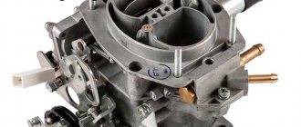
The majority of VAZ cars of the Samara family, and in particular the VAZ-2109, came off the assembly line with a carburetor power system, and only later a small series received injectors. The carburetor system has a simple design and is quite reliable, but its main component, the carburetor, requires periodic adjustment. The VAZ-2109 and other models of the family were equipped with Solex carburetors, characterized by a relatively simple adjustment technology that every car enthusiast can perform.
There are two main carburetor settings - the fuel level in the float chambers and the engine speed at idle (idle). These adjustments are carried out when the engine is unstable at idle and when certain symptoms of improper operation of the power system appear:
These problems indicate that the fuel level in the chamber is not normal.
Disassembling carburetor 2108, 21081, 21083 Solex:
Thank you very much for such a detailed and thorough answer! There seem to be no problems with acceleration and failure. There is a moment when you stand at idle for a long time, the engine warms up well, the fan turns on several times, or, say, in the summer, when the engine temperature rises above normal (turned off the engine, went to run errands, returned, started it), then there are several dull moments at start and during driving time, but after a minute everything is smooth. There were different thoughts, but I decided to try moving the distributor to +. So far no dull spots have appeared.
The second chamber transition system is necessary to force the supply of fuel when the second chamber throttle begins to open, in order to enrich the mixture and prevent “failure”. Approximately, this is a transition from medium loads to power loads, for example, acceleration when moving at average speed. If the fuel intake tube is cracked above the fuel level in the float chamber, then the vacuum (by which the fuel is “sucked out”) in the transition system will decrease, little gasoline will flow under the throttle valve and a “failure” will occur. If the tube is cracked on the part that is immersed in gasoline, then in principle there is nothing terrible. In most cases, the operation of the second chamber transition system is invisible and insignificant. Therefore, if there is no pronounced “failure” in the operation of the engine when accelerating the car in motion, then you can not pay much attention to this problem.
Thanks for the answer! It seems to be doing its job - it is blowing, but I can’t figure out where the impact is, is the tube intact or not... and if not... then what effect can this have? It is flattened near the entrance of the tube into the body.
These tubes did not have to be changed. I changed the tube in the CXX channel. There you need to insert a 2 mm drill inside, wrap the tube with a piece of sandpaper, grab it with pliers and pull the tube out of the socket. The effort when pulling out the tube is not very large. The new tube was simply inserted into the hole and lightly tapped on top with a hammer. Of course, a drill cannot be inserted into the tubes of the econostat and the transition system, so there is a risk of damaging them. But if the tube is already damaged, then it is quite possible to pull it out and replace it with another one. If possible, it is of course better to look for a different carburetor cap.
Colleagues, please tell me how the tubes of the econostat and the transition system of the second chamber are mounted? Someone flattened the tube of the transition system of the second chamber for me. I haven’t yet understood why exactly this was done. Apparently... to save fuel. But for some reason I don’t really like her look. The blow was apparently a screwdriver. So I’m thinking... is it possible to replace it?
How did you check this? If the return to the tank
I took it apart, washed it, cleaned it, and took a used 83 Solex. Economizer of power modes, I did this: I turned off the jet, removed the spring from the diaphragm. I installed a few jets in 1kam.tzh-85 and distributed a few; vzh-168; in the second tzh-95; vzh-125; Returning directly to the tank is a must. Result: I drove 1 liter for 15.5 km. But I haven’t corrected everything yet. But the car is a classic, not inferior to almost anyone.
VAZ carburetor models are a classic of the domestic automobile industry that cannot be avoided. Despite all the shortcomings of such cars, they have one advantage that makes them popular among drivers - low price. Many people buy a VAZ 21083 with a carburetor as their first car.
History and design - what is remarkable about the VAZ 21083?
At the end of the 80s, when the first VAZ 21083 rolled off the assembly line, the carburetor type of engine had a monopoly - they had not even dreamed of VAZ injectors then. From the first days, this model received high ratings from drivers as one of the best in the VAZ series. However, then little thought was given to the price of gasoline, which cannot be said now.
The VAZ 21083 car has 2 doors, a very good streamlined shape, which is important when driving, and also handles well on the road. The main characteristics of this model are a 1.3 liter four-cylinder engine. Some models were produced with a capacity of 1.1 liters, but they did not perform very well. The production of such cars was more of a test nature, and only a few cars were produced.
VAZ 21083 has about 70 l/s in its engine and is capable of reaching speeds of up to 160 km/h. Due to its Solex carburetor, this car model is quite economical. Average consumption reaches 5.5–6 liters per 100 km. The carburetor is very technically well thought out and is not picky about fuel quality.
Solex carburetors were first used in France, where they got their name. At factories on the domestic market, this type of device was redesigned and some changes and improvements were made. Solex-type carburetors began to be installed on cars almost immediately with the first releases of this VAZ model.
The most noticeable change in the engine design was the installation of the carburetor not along, as in previous VAZ models, but across. It was necessary to change the design of the engine under the hood because it was necessary to improve and make the operation of the engine in the car more stable during large ascents and sharp descents. Later, this type of carburetor began to be used and installed on all VAZ cars.
Carburetor design - what is responsible for what?
The Solex carburetor in a car serves to supply the fuel mixture to the engine, where it is further ignited. It mixes the required amount of fuel with air, the ratio of which varies depending on the speed of movement. The VAZ 21083 carburetor consists of two chambers. It is in them that fuel is supplied and mixed for further work. The entire main process takes place in the second chamber.
The main mechanism in the operation of the device is the econostat; it is located in the second chamber of the carburetor. Due to its operation, when driving at high speed, the fuel mixture is enriched with oxygen. The fuel in the carburetor rises through the pipes. The carburetor jets are responsible for the correct and uniform supply of fuel. Therefore, it is very important that they are configured correctly.
The air supply to the carburetor occurs through special channels in the chamber and is controlled by the throttle valve. In the first chamber, the throttle valve is adjusted using the accelerator. In the second chamber, it opens and closes automatically.
In the cold season, it is much more difficult to start the VAZ 21083 engine than in the warm season, and therefore a more saturated fuel mixture is required. The starting device in the car is responsible for preparing such a mixture. The starting device performs the process of retracting the throttle spring, then the air damper opens under the air flow, resulting in uniform mixing of the fuel mixture.
The economizer is responsible for idling the car in the Solex carburetor. It consists of elements such as a switch, a control unit and a solenoid valve. When the engine is idling for a long time and forcibly, the speed can reach up to 2000 rpm. During normal operation, this value should not exceed 900-1000 rpm. During this, the economizer is activated, which, using the control unit and its valve, shuts off the fuel supply to the idle system. It also cuts off the fuel supply during sudden engine braking and during engine operation when driving downhill. This type of device also serves to prevent large emissions of carbon dioxide into the atmosphere.
Setting the fuel level
Adjusting the amount of fuel in the chambers of Solex carburetors is a common procedure and does not require special equipment. Although in industrial conditions this adjustment is made using a special template, which simplifies and speeds up the work. But at home it is possible to do without this template. To carry out adjustment work yourself, you need:
- screwdrivers (phillips, flat);
- ruler (preferably a caliper);
- a round rod with a diameter of 2 mm (wire or drill will do).
With such equipment, you can quickly complete all the work.
Breakdowns and their elimination - we repair the carburetor
Quite often, car owners encounter problems with the Solex carburetor. This happens while the car is moving, as well as when the engine is idling. It is quite easy to identify problems with the carburetor.
- When you try to start the car, it may stall, the tachometer speed on the instrument panel floats.
- When idling, exhaust may appear from the car pipe.
- While driving and changing gears, there may be dips in the gas pedal.
What jets should be on an ozone carburetor?
— Fuel, air and emulsion jets of the Ozone carburetor econostat
Dynamic Solex carburetor from a conventional carburetor in one movement
Carburetors Ozone 1st chamber 2nd chamber
| 2140-1107010-50 | — | 1.20 – fuel 1.40 – air 1.20 – emulsion |
| 2140-1107010-70 | — | 1.20 – fuel 1.40 – air 1.20 – emulsion |
| 2141-1107010 | — | 1.20 – fuel – – air – – emulsion |
Repair stages - what to turn and where to adjust?
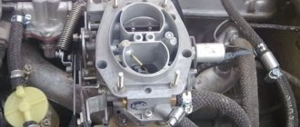
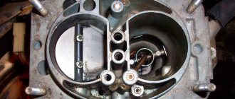
The carburetor in the VAZ 21083 is located under the air filter cover. To remove it, you need several keys. Before this, you need to open 4 latches. After this, loosen all the clamps that go to the carburetor. Next, disconnect the contact wire from the solenoid valve and unscrew the carburetor cap. You need to remove it in such a way as not to catch the walls of the floats in the chamber, because you can break them.
The floats in the carburetor chamber must be parallel to each other. If there are any deviations or inaccuracies in the operation of the floats, the fuel will be distributed unevenly throughout the chambers. The chambers have red marks on the body that indicate the permissible fuel level.
The jets inject fuel into the engine. Normal working jets have three holes. With very long operation and low-quality fuel, they wear out, as a result of which fuel is supplied in the wrong quantity. Adjustment of the jets must be done gradually. When replacing, they must be tightened firmly without using significant force.
When using a car regularly, timely cleaning of the Solex carburetor is very important. It is strongly recommended to carry it out at least once every six months. This will significantly extend the life of your carburetor and provide a more comfortable ride for your car.
Setting the fuel level
Adjusting the amount of fuel in the chambers of Solex carburetors is a common procedure and does not require special equipment. Although in industrial conditions this adjustment is made using a special template, which simplifies and speeds up the work. But at home it is possible to do without this template. To carry out adjustment work yourself, you need:
- screwdrivers (phillips, flat);
- ruler (preferably a caliper);
- a round rod with a diameter of 2 mm (wire or drill will do).
With such equipment, you can quickly complete all the work.
Setting up the float chamber
This type of work allows you to adjust the optimal amount of gasoline in the float chamber. An incorrect level causes a decrease in power, uneven engine operation, and excessive fuel consumption.
- set of wrenches;
- thin probe (diameter 1 mm);
- pliers.
1. Remove the air filter and unscrew the carburetor cover.
2. Carefully remove the float chamber cover.
3. Check the condition and position of the floats. They should be parallel to the imprints of the side walls of the float bath on the gasket.
4. If they are displaced, we align them by bringing them together or spreading them apart.
5. Next, lay the lid horizontally with the floats up and use a feeler gauge to measure the distance from the bottom of the float to the gasket. It should be equal to 1 mm. If it is higher or lower, we continue further adjustment after installing the carburetor on the engine.
6. When fuel is pumped into the float chamber, its level should coincide with the red lines, as shown in the photo.
7. If the floats are set incorrectly, this level will be lower or higher. Simple adjustment is carried out by bending or bending the tongue of the floats, then closing the carburetor cover and pumping fuel.
For details on setting up the float chamber, see here
Setting up the launcher
- open-end wrench 7;
- open-end wrench 8;
- flat screwdriver;
- electronic tachometer or multimeter with its function.
1. Remove the air filter from the carburetor. Pull the “suction” towards you as far as it will go. Next, you will need an assistant to start the engine. At this time, you are watching the starter flap, which should open slightly after starting.
2. If this does not happen, it means that the starter is not adjusted.
3. We begin the adjustment. Warm up the engine, turn it off and connect the tachometer as follows.
4. Pull out the choke and start the engine. The suction valve must be completely closed.
5. Next, use a screwdriver to press on the edge of the damper, opening it 30 0 .
8. In this position, holding the bolt with a screwdriver, tighten the locknut.
The adjustment process can be seen in this video
Idle setting
- flat screwdriver;
- electronic tachometer.
1. Start the engine, warm it up to operating temperature, and then turn it off. We press the “choke” all the way, opening the flap of the starter device as much as possible. We connect the tachometer using the same principle.
2. Start the engine, turn on all the lights and the heater fan at full power.
4. If in this way it was not possible to achieve the required speed, unscrew the quality screw to the maximum number of revolutions. Next, turn the quantity screw, setting the motor to 900 rpm. After this, use the quality screw to reduce the speed to 800 rpm.
Details in the video
Adjusting the ignition angle
Sluggish acceleration of the car and instability of the idle speed are also often associated with incorrectly set ignition; mainly, this function is performed in car repair shops using special equipment. But if desired, the adjustment is easy to make without the help of others, and also without a strobe, and quite accurately:
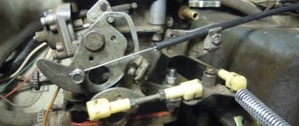
- with the engine stopped, loosen the three nuts securing the distributor (the third fastening is located at the bottom, it is not visible from above);
- we start the car, turn the distributor-distributor clockwise (to “”), and if the ignition was set later, the idle speed will increase noticeably;
- we select the best position of the distributor (the operation of the internal combustion engine should be smooth, without failures), reduce the speed with the quantity screw, turn off the engine, secure the distributor-distributor with one nut for now, and check the results of the ignition adjustment on the go.
READ Replacing the carburetor with an injector VAZ 2109
If, under heavy load and sharp acceleration, the fingers begin to noticeably “knock” (engine detonation occurs), the distributor should be slightly moved to “minus”, then check the car again while driving. This way you can set the ignition quite accurately, and sometimes even better than with a strobe light.
Design and operating principle
The carburetor supplies the engine with a fuel-air mixture in various modes. When starting from a “cold” state, the throttle valve is manually fully opened (the so-called “choke”), and the mixture entering the cylinders is completely enriched. After the engine warms up, the speed drops and the choke can be removed. Drivers remove it in different ways, but it is recommended to do it gradually.
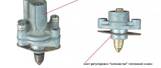
The fuel in the carburetor is transferred to the float chambers from the diaphragm pump, and the needle valve controls the gasoline level. Through the chamber, the fuel passes into the channels of the body, where it enters the nozzles, and through them it goes into the first chamber. A fuel-air mixture is formed, which is supplied directly to the cylinders by the gas pedal. The second camera turns on only during sharp acceleration and operation at high speeds.
At idle, the IACV (idle speed solenoid valve) is turned on, while the engine runs stably and the car consumes much less fuel. However, on some devices it can be disabled; if it breaks down, the speed and consumption will only increase slightly, but the car will drive.
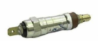
Applicability
| Brand | Model | Name according to auto catalog | Drawing |
| VAZ | VAZ-2107 | Fuel valve | Engine/Power System |
| VAZ | VAZ-2107 | Fuel valve | Engine/Power System |
| VAZ | VAZ-2108 | Fuel valve | Engine/Power System |
| VAZ | VAZ-2108 | Fuel valve | Engine/Power System |
| VAZ | VAZ-2109 | Fuel valve | Engine/Power System |
| VAZ | VAZ-2109 | Fuel valve | Engine/Power System |
| VAZ | VAZ-21099 | Fuel valve | Engine/Power System |
| VAZ | VAZ-21099 | Fuel valve | Engine/Power System |
| VAZ | VAZ-2110 | Fuel valve | Engine/Power System |
| VAZ | VAZ-2111 | Fuel valve | Engine/Power System |
Where else is the spare part used?
The parts data presented on this page is for informational purposes only.
Signs of a carburetor malfunction
It is a well-known fact: the quality of fuel in our country leaves much to be desired. As a result, the carburetor may become clogged with oils, solid particles, etc.
In this case, one or more signs may be observed:
- significantly increased fuel consumption;
- the engine does not start “cold”;
- loss of dynamics;
- "triple" of the engine.
You can restore functionality yourself. If unsuccessful, you can remove it and take it to a mechanic, who, with an experienced eye, will immediately identify the errors and adjust it “by eye,” after which the car will at least start.
First, you can try adjusting the carburetor without removing it from the car.
Setup and adjustment
First of all, the engine warms up until the fan turns on. Next, adjust the speed by ear using the quantity screws. The operation should be smooth, with a sharp press on the gas pedal there should be no dips, and the speed should increase quickly and smoothly. The quality screw regulates the amount of exhaust gases. Ideally, no escaping gases should be visible from the exhaust pipe in the dry season (they will be, but not visible to the eye, if everything works correctly). Everything can also be done by looking at the tachometer readings. Unfortunately, many models of Soviet cars do not have it at all, so most often the adjustment will have to be done by ear.
For complete adjustment, cleaning and tuning, the carburetor is removed from the car. Procedure for removing the device from the car:
- the air filter and its housing are removed;
- all tubes and cables are disconnected;
If you are not sure that you will be able to put everything back, you can photograph all fastenings before disconnecting, for example, with a mobile phone camera.
Take care of the place where the work will be performed. It should be ventilated, free from various suspensions, the table should be wiped and covered with a cloth or old newspapers. It is better to have a carburetor diagram before your eyes. It is advisable to place small parts in various jars and boxes strictly in order. Prepare a container for solvent brand “646”. Buy a repair kit for your carburetor, it costs mere pennies.
- look at the floats. They must be parallel to each other. If there is any mechanical damage, replace it with new ones without hesitation. The needle valve should move freely in the seat, and the ball should not linger anywhere;
Adjusting the ignition angle
Sluggish acceleration of the car and instability of the idle speed are also often associated with incorrectly set ignition; mainly, this function is performed in car repair shops using special equipment. But if desired, the adjustment is easy to make without the help of others, and also without a strobe, and quite accurately:
- with the engine stopped, loosen the three nuts securing the distributor (the third fastening is located at the bottom, it is not visible from above);
- we start the car, turn the distributor-distributor clockwise (to “”), and if the ignition was set later, the idle speed will increase noticeably;
- we select the best position of the distributor (the operation of the internal combustion engine should be smooth, without failures), reduce the speed with the quantity screw, turn off the engine, secure the distributor-distributor with one nut for now, and check the results of the ignition adjustment on the go.
If, under heavy load and sharp acceleration, the fingers begin to noticeably “knock” (engine detonation occurs), you should move the distributor a little to “minus”, then check the car again while driving. This way you can set the ignition quite accurately, and sometimes even better than with a strobe light.
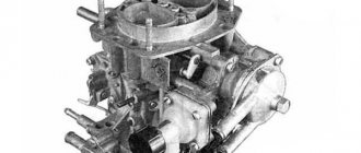
Lada 2106. › Logbook › Solex carburetor 083 (Pekar) a lot of literature. And Photos of works.
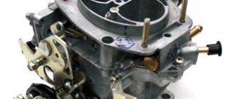
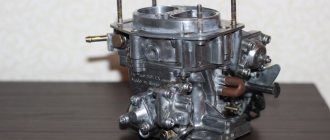
The figure shows a VAZ Solex 21083 carburetor.
The design of the carburetor VAZ Solex 21083.
1. Carburetor heating unit 2. Throttle valve of the first chamber 3. Pipe for suction of crankcase gases 4. Accelerator pump drive lever 5. Accelerator pump drive cam 6. Accelerator pump diaphragm 7. Power mode economizer fuel nozzle 8. Pump housing 9. Economizer diaphragm power modes 10. Shut-off solenoid valve 11. Idle fuel jet 12. Carburetor cover 13. Main air jet of the first chamber 14. Air damper 15. Accelerator pump nozzles with fuel supply valve 16. Starter diaphragm 17. Starter adjustment screw 18. Adjusting screw for the amount of idle mixture 19. Locking lever of the second chamber 20. Pipe for supplying vacuum to the vacuum regulator of the ignition distributor 21. Adjusting screw for the quality of the idle mixture 22. Throttle valve control sector 23. Throttle valve drive lever 24. Adjusting screw for opening the throttle damper of the first chamber 25. Air damper control lever 26. Starter rod 27. Electrical wire of the limit switch of the forced idle economizer 28. Air damper lever 29. Main air jet of the second chamber 30. Emulsion tube 31. Sprayer of the main dosing system of the second chamber 32. Fuel supply pipe 33. Fuel drain pipe into the tank 34. Fuel filter 35. Needle valve 36. Second chamber throttle valve 37. Second chamber throttle lever 38. Second chamber main fuel jet 39. Second chamber throttle drive lever 40. Float
Adjusting the carburetor VAZ 2109
Adjusting the float position
1
.
Start the engine and let it idle for about 3 minutes. 2
.
Open the hood and remove the air purification filter 3
.
Disconnect the hose that supplies fuel to the carburetor 4
.
Unscrew all the bolts that secure the top of the carburetor and carefully remove it. 5
.
Now take a caliper and measure the height of the fuel level in the float chamber. It should be approximately 25.5 mm. If the level is not at the normal level, then you need to adjust the metal float by applying pressure to the tongue of a special bracket. 6
. Reassemble all components in the reverse order and repeat the process until the level returns to normal.
Setting the carburetor trigger
All actions are performed with the carburetor removed. 1
.
Close the air supply damper by turning the special lever 2
.
Using a screwdriver, you need to recess the starter rod 3
.
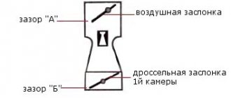
Now measure the gap that appears between the chamber wall and the opened damper, compare it with the tabular data for your carburetor model and, if necessary, adjust it. To do this, loosen the special nut located on the accelerator pump and use a screwdriver to unscrew or tighten the adjusting screw. When unscrewing it, the gap increases, and when tightening it, it should decrease. 4
. Now measure the gap formed by the damper of the first chamber (necessarily with the air chamber closed). The measurements must correspond to the tabulated data. If the measurement results do not correspond to the standards, then adjustment is made by rotating the throttle position adjustment screw.
Adjustable idle speed
1
.
It is necessary to tighten the screw responsible for the quality of the mixture until it fully stops. Then unscrew it 3.5 turns, start the engine and turn on the fan and high beams. Attention! The choke must be removed and the engine warmed up to nominal values! 2
.
Using the screw, which is designed to adjust the amount of mixture, set the speed to 750-800 rpm. 3
.
Using the mixture quality adjustment screw, set the maximum possible speed. 4
.
Now you need to use the quantity screw to create 900 rpm. 5
.
At the same time, tighten the quality screw until the speed drops to 800 rpm. Then tighten until the motor shows signs of unstable operation, and unscrew the screw half a turn. 6
. Then set the speed with the quantity screw: • In summer, the speed should always be maintained in the range of 800-900 • In winter, the speed should be 900-1000 This completes the carburetor adjustment. A properly configured carburetor should achieve the most stable engine operation with the lowest fuel consumption.
Carburetor calibration data 21083—1107010—31
| Options | First camera | Second camera |
| mixing chamber diameter, mm | 32 | 32 23 |
| diffuser diameter, mm | 21 | |
| Main metering system: fuel jet marking* air jet marking | 95 155 | 100 125 |
| Emulsion tube type | 23 | WITH |
| Idle system and transition systems: fuel jet markings air jet markings | 41+3 170 | 50 120 |
| Econostat: conditional flow rate** of the fuel jet | — | 70 |
| Power mode economizer: fuel nozzle marking spring compression force at a length of 9.5 mm, N | 40 1 ,5 | 10% |
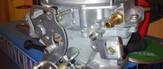
Solex 21083 carburetor design
1 – driving lever, second drive chamber; 2 – screw adjusting the amount of mixture supplied for idle speed; 3 – sector for heating the carburetor; 4 – engine crankcase ventilation pipe; 5 – drive lever for the accelerator pump; 6 – solenoid shut-off valve; 7 – air damper lever; 8 – carburetor cover; 9 – special screw for fastening the liquid chamber; 10 – liquid chamber body; 11 – carburetor body; 12 – throttle valve lever of the second chamber; 13 – control lever block directly for the throttle valves; A - special marks for precise installation of the bimetallic spring of the starting device.
1 – axis for the float; 2 – needle valve; 3 – float; 4 – special gasket for the carburetor cover; 5 – starter cover; 6 – screw; 7 – trigger device diaphragm; 8 – special gasket; 9 – air damper lever; 10 – idle fuel jet; 11 – solenoid shut-off valve; 12 – pipe for supplying a combustible mixture; 13 – carburetor cover; 14 – fuel filter; 15 – housing assembly with drive levers of a semi-automatic starting device; 16 – screws for adjusting the air damper of the starting gap and slightly opening the first throttle chamber; 17 – special clamp for securing the bimetallic spring housing; 18 – liquid chamber; 19 – assembled housing with a bimetallic spring; 20 – bimetallic spring screen.
Solex 21083 carburetor diagram
1 – screw adjusting the amount of feed mixture for idle speed; 2 – electric wire of the limit switch economizer for forced idling; 3 – carburetor heating unit; 4 – diaphragm for the accelerator pump; 5 – accelerator pump cover; 6 – drive lever of the accelerator pump; 7 – accelerator pump drive cam; 8 – economizer cover for power modes; 9 – diaphragm for economizer of power modes; 10 – fuel jet for power mode economizer; 11 – power mode economizer valve; 12 – nozzles with a fuel mixture supply valve for the accelerator pump; 13 – sprayers of the main dosing systems; 14 – air main jets with emulsion tubes; 15 – fuel main jets; 16 – carburetor body; 17 – adjusting screw for the throttle valve; 18 – stopper for the adjusting screw; 19 – stopper cap; 20 – throttle valve of the second chamber; 21 – throttle valve axis of the second chamber; 22 – throttle valve rod for opening the first chamber; 23 – block with throttle valve control lever; 24 – return spring of the throttle valve of the first chamber; 25 – driven lever, drive of the throttle valve of the second chamber; 26 – driving lever, driving the throttle valve of the second chamber; 27 – spring of the throttle valve drive levers of the second chamber; 28 – throttle valve of the first chamber; 29 – return spring of the throttle valve of the second chamber; 30 – plug for the screw adjusting (composition) the quality of the idle mixture; 31 – axis of the throttle valve of the first chamber; 32 – screw adjusting the quality of the supplied idle mixture
The carburetor is equipped with two main metering systems, the second and first chambers, an idle system with a transition system of the first chamber. A transition system of the second chamber, an econostat, an economizer of power modes, a semi-automatic starting device and an accelerating diaphragm pump.
The Solex 21083 carburetor, the price of which is about 4,500 rubles ($150) and remains acceptable for motorists, has earned its recognition due to its excellent technical characteristics and efficiency. In addition, malfunctions of the Solex 21083 carburetor, which occur quite rarely, are easily fixable if you follow the instructions for eliminating them.
Some car enthusiasts prefer to modify the factory Solex 21083 carburetor to suit their preferences, increasing its power, and thereby the throttle response of their car. There are several options for properly tuning the Solex 21083 carburetor, so, if you wish, you can seriously improve the overall performance of your car.
Cleaning and checking the technical condition of carburetor parts
Fuel filter
Wash the filter in gasoline and blow with compressed air.
Check the condition of the filter. If the filter or fuel supply pipe is damaged, replace it with a new one.
Float mechanism
Wash the parts in gasoline and check their condition.
The floats must not be damaged.
The sealing surface of the needle valve and its seat must not be damaged to impair the seal of the valve.
The valve should move freely in its seat and the ball should not hang up.
The weight of the floats should not be more than 6.23 g. Replace faulty parts with new ones.
Carburetor cover
Clean the cover and all holes and channels from dirt and oil.
Wash the lid in acetone or gasoline and blow with compressed air.
Inspect the sealing surfaces of the cover. If there is damage, replace the cover with a new one.
Semi-automatic starting device
In order not to disrupt the lubrication properties of bushings, axles and levers, it is forbidden to wash the device body and its parts.
Jets and emulsion tubes
Clean the jets and emulsion tubes from dirt and resinous compounds, rinse them with acetone or gasoline and blow with compressed air.
Do not clean the jets with a metal tool or wire, or wipe the jets and other carburetor parts with cotton wool, cloth or rags, as lint can clog the fuel emulsion path.
If the blockage is severe, you can clean the jets with a soft wood needle moistened with acetone.
Carburetor body
Clean the housing from dirt and oil.
Rinse its channels with acetone or gasoline and blow with compressed air.
If necessary, clean the channels and emulsion tubes with special reamers.
Inspect the sealing surfaces of the housing; if they are damaged or deformed, replace the housing with a new one.
Acceleration pump
Clean the pump parts, rinse them in gasoline and blow with compressed air.
Check the ease of movement of the ball in the sprayer and the movement of the moving elements of the pump (lever, diaphragm parts).
Jams are not allowed. the diaphragm must be intact and without damage.
Check the condition of sealing surfaces and gaskets. Replace damaged parts with new ones.
Power mode economizer
the diaphragm must be intact and without damage.
If the total length of the diaphragm pusher (including the head) is less than 6.0 mm, replace the diaphragm and pusher assembly.
Carburetor assembly
Assemble the carburetor in the reverse order of disassembly. In doing so, pay attention to the following points.
The float must rotate freely on its axis without touching the walls of the chamber.
The needle valve should slide freely in its seat, without distortion or jamming, the tightening torque of the needle valve seat should be 14.7 Nm (1.5 kgcm).
The tightening torque of the solenoid shut-off valve should be 3.68 Nm (0.4 kgcm).
To avoid mixing up the jets during assembly, pay attention to the markings of the jets.
When assembling the accelerator pump, tighten the screws securing the cover, press the drive lever all the way, tighten the screws and release the lever.
When tightening the throttle valve mounting screws, tap the screws along the contour using a special device to prevent deformation of the valve axes.