Domestic ones have long moved away from the concept of producing completely mechanical components with a minimum amount of electronics.
The modern Chevrolet Niva model is a car with an injection engine, the operation of which is completely under the control of electronics. The article examines the problem of why the speedometer on a Niva Chevrolet does not work. The causes of the malfunction, the symptoms preceding them, and methods for checking all components of the speed counting system will be discussed.
Description of DS
As we have already said, the main purpose of the speedometer drive sensor is to accurately determine the speed of the vehicle. Thanks to this device, the model can always know at what speed his car is moving. As for the varieties, DS can be of the contact or non-contact type. Today, most of our compatriots prefer contactless options. Contact DS, despite all the advantages, have one significant drawback - they are prone to contamination, which in turn will lead to inaccuracy of the displayed readings.
Design and principle of operation
Structurally, according to the diagram, this part consists of:
- speedometer drive;
- housings;
- as well as the controller itself with a connector for connecting to the on-board network.
As for the principle of operation, it is based on measuring the frequency level of signals from the controller, which is located on the gearbox housing or transfer case. At the output of the device, while driving, rectangular pulses are formed, the minimum value of which should be at least 1 volt, and the maximum value should be at least 5 volts.
According to international standards, the controller must generate about 6 thousand such pulses over one kilometer. The pulses themselves are subsequently converted into current, which is measured by a magnetoelectric device. It should be noted that the current value directly depends on the number of signals supplied per certain unit of time. That is, this value will be directly proportional to the speed of the vehicle.
In addition, thanks to the electronic circuit installed in the dashboard, the operation of the stepper motor is ensured by counting incoming signals. The latter is designed to rotate the counter reels, after which it displays the relevant information on a small screen, where the total and daily mileage of the car is shown. If we are talking about daily mileage, then this value can be reset to zero if necessary.
Symptoms of a problem
If the DS for some reason fails, this will lead to the control unit being unable to determine the speed of movement. However, this is not the only problem, since malfunctions in the performance of the power unit may also occur.
We suggest that you familiarize yourself in more detail with the signs of a malfunction, by which you can determine the failure of the DS:
- the speedometer on the dashboard has either stopped working altogether or displays incorrect readings;
- malfunctions appear in engine operation, in particular at idle speed;
- fuel consumption increased;
- engine performance has deteriorated, the power unit cannot reach the required speed;
- the engine may stop spontaneously while idling, in particular when the driver tries to press the clutch to change gear;
- if the car is equipped with an on-board computer, a Check indicator may appear on the dashboard;
- if the car is equipped with an electric power steering, this unit may also fail;
- in some cars, for example, Lada Kalina, failure of the diesel engine can also lead to increased sensitivity of the fuel level controller in the gas tank (the author of the video is the Autoelectrics HF channel).
As for the reasons, as a rule, they are caused by damage to the car's electrical wiring, so checking the functionality should begin with diagnosing the condition of the contacts and electrical circuits. Perhaps the problem lies in oxidized or dirty contacts, so they will need to be cleaned and treated with a lubricant, for example, Lithol. A broken wiring should be looked for first of all near the connection connector, since in this place the wires are bent and usually frayed.
Also, the cause of the malfunction may be a violation of the integrity of the wiring insulation in the area where the exhaust manifold is installed. At elevated temperatures, the insulation may melt, causing the device to short out. Also, the DS may transmit incorrect readings due to a worn speedometer cable. Over time, cracks and tears form on it, which contributes to the failure of the controller.
Basic elements of the electrical system
The vehicle's on-board network is designed so that all components and assemblies function smoothly, and control is as comfortable as possible. According to international standards, the voltage is 12V to be compatible with most consumers.
The circuit itself is single-wire. In practice, this means that the “negative” terminal is connected to the car body, and each individual device is powered by a “positive” wire. This greatly simplifies the routing of wires along the body and reduces the number of wires required. It also reduces the likelihood of cable damage and, as a result, a short circuit.
Source
Functionality check
There are several options for diagnosing DS.
The first way to check is with a multimeter:
- First you need to dismantle the DS.
- Then, using a tester, you should determine what each contact on the connector is responsible for; you need to find exactly the pulse one.
- After this, the positive probe of the tester must be connected to this contact, and the negative probe to the power unit or car body.
- Next, you should install a piece of tube on the controller axis and start rotating it at low speed. At the same time, monitor the controller readings - the higher the rotation speed of the DS tube, the higher the values on the tester display and the voltage parameter will be (the author of the video is the REMONTYCA channel).
Second method, without removing the controller:
- Using a jack, you will need to lift the front wheel of the car. Which one - right or left - does not matter.
- Then the tester should be connected to the DC wiring.
- After this, you begin to rotate the car wheel with your hands and monitor the readings on the tester display. If there are impulses, then this indicates that the DS is operating in normal mode.
If you don’t have a multimeter, you can diagnose the DC using a test light or any other 12-volt lamp.
DIY replacement instructions
The self-replacement procedure is as follows:
- First you need to turn off the ignition, open the hood and disconnect the terminals from the battery.
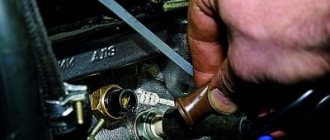
- Next, you will need to find the DS itself. As stated above, the location of the controller may vary, so check the installation location in the service book. When the DC is found, you will need to clean the area around the controller from dirt. This is done in order to prevent contaminants from entering the transmission.
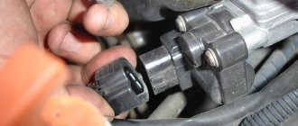
- Disconnect the power connector from the speed sensor.
- Next, you will need a wrench to unscrew the device. If you cannot unscrew the device the first time, you do not need to apply force, as this may damage the case (usually it is made of plastic). It is better to treat the DS with WD-40 liquid and wait a few minutes.
- When the device is removed, it is necessary to install a new controller, then connect a new sensor.
- If your car is equipped with a control unit, then after replacing it you need to reset its errors. It happens that due to the fact that the error is not reset, the indicator on the dashboard continues to light, and the control unit sends signals about its malfunction.
Photo gallery “Changing the speed sensor”
Fuse
They are located directly in the mounting block.
According to the pinout of the fuse links, there is no separate element for the sensor. The on-board circuit only has a fuse responsible for part of the wiring. This is argued by the fact that the element does not have a separate power supply system - the positive conductor is connected directly to the DVTZh. The fault should be looked for directly from fuse F19.
Video “Visual instructions for replacing DS”
We offer a more visual understanding of the process of replacing a speed sensor using the example of a VAZ 2110 car (the author of the video is the channel In Sandro’s Garage).
When the car stalls at idle, it is necessary to check the condition of several sensors - DS, MAF, TPS. You can always check the speed sensor yourself; there are three simple ways to do this. At the same time, the sensor and its erroneous data threaten not only the condition of the engine, but also other components of the car. Therefore, it is so important to understand the principle of operation of the DS and its main malfunctions.
Installation of the VAZ 2110 dashboard on Lada 4×4 (VAZ 2121, 2131)
Lada 4×4 has been produced for more than 39 years and during this time the interior of the domestic SUV has remained virtually unchanged. However, you can make the car interior more comfortable with the help of various modifications. For example, install a more modern instrument panel from a VAZ 2110 on a Niva.
You will need: a VDO instrument panel with catalog number 21150-3801010, an instrument cluster trim (article: 21214-5325124-00), a speed sensor, for a carburetor Lada 4×4 you also need a gasoline level sensor from the injection system, at least 8 female terminals , wire 0.75 about 10 m.
We remove the old dashboard. The white and red blocks of the new instrument panel have a different pinout (see diagram of the Lada 4×4 panel), so the main task is to reconnect the wires in the right order.
| White block number | Old panel | New panel | Color |
| 1 | Empty | Housing (weight) | Black (optional) |
| 2 | High beam warning lamp | Low voltage tachometer input | Brown-red |
| 3 | Dimensions indicator lamp | High voltage tachometer input | Brown |
| 4 | To terminal “15” of the ignition switch | To terminal “30” of the ignition switch | additional from class "30" |
| 5 | To the hazard switch | To the indicator sensor | green |
| 6 | To terminal "D" of the generator | Side light warning lamp | yellow |
| 7 | Empty | Choke (carb models) | Grey |
| 8 | PTF warning lamp | "Check Engine" lamp | black and white |
| 9 | Warning lamp for heated glass | To terminal 15 of the ignition switch | blue |
| 10 | "Check Engine" lamp | To terminal 15 of the ignition switch | Orange |
| 11 | To fuel level sensor | To "VK" parking brake | pink-black |
| 12 | "Check Engine" lamp | To terminal "D" of the generator | brown-white |
| 13 | To the indicator sensor | To oil pressure sensor | gray-blue |
| Red block number | Old panel | New panel | Color |
| 1 | Empty | To air temperature sensor | Additional |
| 2 | To terminal “15” of the ignition switch | To terminal “15” of the ignition switch | Leave |
| 3 | Low voltage tachometer input | Housing (Weight) | Black |
| 4 | To the instrument lighting control | To the instrument lighting control | Leave |
| 5 | High voltage tachometer input | To the right direction indicators | Blue (Optional) |
| 6 | Housing (weight) | To the left direction indicators | Blue-Black (Optional) |
| 7 | To terminal “50” of the lock. (starter) | To brake fluid level sensor | Pink |
| 8 | To the parking brake switch | To the trip computer | |
| 9 | Empty | To speed sensor output | Additional |
| 10 | To the fuel reserve lamp | To fuel level sensor | Rose red |
| 11 | To differential lock sensor | Towards the distant light | Green-black |
| 12 | To oil pressure sensor | To off alarm | |
| 13 | To brake fluid level sensor | To terminal “50” of the ignition switch (starter) | Red-blue |
The differential lock was connected to the choke lamp. For turn signal lamps, additional wires should be laid from the hazard warning button. The wires for heating the rear window (green-red), rear foglights (orange-black) and turn signals (blue-white) remain unused.
We install and connect the speed sensor (the pinout of the sensor is on its plug). We connect the positive wire from the speed sensor to the upper left fuse box, and take the negative wire from the pin that holds the panel. And we bring the signal wire to the instrument panel.
It is worth noting that after installing the instrument cluster from the VAZ 2110 VDO with two windows, we not only get a more modern SUV interior, but also the ability to display the outside temperature, clock and voltmeter on the panel.
By the way, do you know how to tune a VAZ 2110 panel? For example, install an overlay, wells or tint!
Read news about the new Niva
- The modernized Lada Niva Legend (4x4) 2021 was shown on the Internet
- Lada 4×4 Bronto - sales stopped, new details » Lada.Online - all the most interesting and useful about LADA cars
- Description of the instrument panel Lada 4×4 (VAZ 2121, 2131) » Lada.Online - all the most interesting and useful about LADA cars
- Chevrolet Niva gasoline consumption per 100 km
- Buy LADA (VAZ) 2131 (4×4) 2022 in Rostov-on-Don, low price for Lada 2131 (4×4) 2022 on the Avto.ru website
- Fuses Niva 21214 injector «
- The new large Lada 4×4 Niva “Bigster” 2021-2022 based on the Dacia Bigster was shown for the first time. The SUV has changed beyond recognition
- New Niva Chevrolet Lux 2022 - review of GLC equipment
What is the working principle of the speed sensor
Modern cars are equipped with a DS that operates based on the Hall effect. Photo: mtsznrb.ru
During operation, the DS transmits frequency-pulse signals, which determine the speed. On average, one kilometer of road contains 6,000 signals.
When a conductor is placed in a magnetic field, an electric voltage is generated - this phenomenon is called the Hall effect. The sensor is located in the speedometer drive mechanism, although the location largely depends on the make of the car.
DS directly affects traffic safety and machine stability. Knowing all these nuances, it is impossible to neglect the situation; it is necessary to restore the operation of the DS or replace it with a new one.
Connection diagram
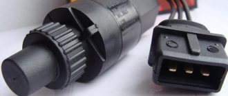
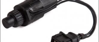
The Shnivy sensor connector itself is a three-pin connector, where:
- red – plus;
- black – minus;
- blue – signal.
The electrical diagram of the element will tell you how the wiring is connected to the speedometer.
Skipping the details and complexity of the speedometer drive pinout, you should focus on connecting the sensor itself. There are three wires here.
- Cable number 1 is a plus, goes to the brake fluid sensor. To maintain constant nutrition.
- The second wire is connected to the speedometer and is responsible for transmitting the signal.
- The third one is black. The cable is responsible for the minus and is connected to another similar wire, or screwed onto the car body, directly at the installation site.
What are the types of DS malfunctions?
If this element malfunctions, it is difficult to determine the speed of the vehicle. Photo: avtomarket.ru
In order to promptly fix a breakdown before it develops into a more expensive repair, every owner must listen to the behavior of the car. At the slightest deviation, it is recommended to replace the DS. The main symptoms of malfunctions include:
- Incorrect speedometer readings;
- Fuel consumption increases;
- The engine does not develop full power;
- At idle, unstable operation can be observed.
In this case, each driver will see a Check engine indicator; if there is an on-board computer, error “24” is displayed.
The first thing you need to do is check the condition of the wires and contacts that could simply break. Most often this happens near the connector, where the wires bend and can fray. If the contacts have oxidized or become dirty, they need to be properly cared for. In the area of the exhaust manifold, the integrity of the wire insulation is monitored. In addition, a malfunction of the DS may be associated with a failure of the speedometer cable, which has simply worn out over the years.
It is better to eliminate car air conditioner malfunctions before they lead to negative consequences. Details are in our material.
Find out how to quickly repair a puncture on a tubeless tire here.
How can you test the DS?
Each car owner should know three possible ways to determine the serviceability of the DC; it is necessary to determine whether it produces 12 V. Since the operating principle is based on the Hall effect, the state of the contacts can only be carried out during rotation, and the voltage readings should be within 0.5 V – 10 V.
- Check with a voltmeter. The speed sensor is removed, it is necessary to determine which terminal is responsible for what. One contact of the voltmeter is connected to the terminal that outputs pulse signals, the second is connected to the ground wire. Rotating the sensor, we look at the voltage readings. The faster it rotates, the higher the indicators should be.
- It is not necessary to remove the DS from the car to determine its operation. To do this, you need to lift it with a jack so that the wheel does not touch the ground. Then connect the sensor contacts to a voltmeter, which will give voltage readings when the wheel rotates. If there is a frequency in Hz and voltage, we diagnose that the DS is working.
- It is necessary to disconnect the impulse wire, which is determined by a special controller. As in the previous version, we lift the wheel to rotate it. The “Signal” wire is connected to the control; if the indicator is “-“, then the DS is working. A wire with a light bulb can replace the control in this procedure.
Troubleshooting
Faults are not always related to the part, i.e. The DS may turn out to be quite functional; only some procedures need to be carried out to restore the previous functionality. Photo: drive2.ru
Dirt, dust deposits and oil smudges may form on the DS during the operation of the car. By cleaning this device, you will ensure preventive maintenance of the product and possibly prevent future breakdowns.
The problem may be in the contacts, their fracture, abrasion, and it is necessary to replace the damaged area.
The problem may turn out to be elementary and be hidden in mechanical damage or defects in the cable, which is easier to replace. Having diagnosed the sensor, everyone is convinced that it is not working properly, then it is worth testing and eliminating the above-mentioned malfunctions.
Meter design and location
The operating principle of the DPRV is based on the Hall effect - the sensor reacts to the approach of a metal mass by changing the voltage on the signal wire. The design of the device is similar to another element - the crankshaft position detector. Inside the plastic case there is a coil where the 12 V on-board voltage is constantly supplied.
The meter is installed on the engine cylinder head in close proximity to the camshaft. The latter is equipped with a special plate or gear, whose rotation affects the DPRV. The work algorithm looks like this:
- After turning on the ignition and starting the engine, a supply voltage of 12 V is supplied to the sensor. Through the third signal wire, the element supplies the controller with a voltage of 90–95% of the original one.
- When the protrusion on the rotating part of the camshaft passes next to the DPRV housing, the voltage at the signal contact drops to 0.2–0.4 volts, depending on the design of the device and the vehicle model.
- When the voltage drops, the electronic unit clearly “sees” the valve timing, promptly supplies the fuel mixture to the engine cylinders and directs the spark discharge to the desired spark plug.
In what cases is replacement required?
DS is a part that does not change very often, this is due to the reliability of the device, which lies in its simple design. Before changing it, you need to make sure that there is a malfunction, because the signs may indicate completely different problems.
The procedure for replacing the speed sensor does not take much time and does not require so much effort, so many people try to carry out this procedure on their own. Follow the order of procedure:
- The battery must be disconnected from the on-board grid, only then disconnect the speed sensor. In this case, two keys are used - “10” and “21”. Although a lot depends on the make of the car.
- The sensor itself is unscrewed, but this must be done carefully, because the rod may be damaged, and then the procedure will become more complicated. It is necessary to purchase the same part with an equal number of teeth on the gear.
- The process of installing a new element is carried out in reverse order. A rod is installed in the sensor sleeve, then an o-ring, which is pre-treated with oil, and finally the device is fixed in its place.
After installing a new DS, it is necessary to reset the ECU errors, otherwise the car will not consider the replacement effective. How to do this - see the example of VW Passat:
What to pay attention to
When carrying out the procedure for replacing the speed sensor, you must turn off the ignition. After all, if there is voltage in the circuit, and you connect a voltmeter, a short circuit may occur, then the remaining elements will definitely fail.
When removing the DS, you may encounter rod defects, so you should dismantle the speedometer drive. The drive is removed using a wrench; it is important to carry out the procedure carefully, removing it from the manual transmission body. Don't miss the rod near the gearbox.
Now everyone can appreciate the importance of DC, which not only indicates speed, but also affects the engine. Therefore, it is important to correct the malfunction in a timely manner, and sometimes resort to replacing the sensors.
6 best thickness gauges for 2022
8 Best G12 class antifreezes
TOP 9 best antifreezes for 2022
How to drain gasoline from the tank of any car
Big test dextron or which one is better to pour
Why does the speedometer on a Chevrolet Niva not work?
In addition to the reasons already mentioned, problems may arise with the vehicle's electrical network. It is best not to try to diagnose and fix the problem yourself - this can lead to unpleasant consequences.
But if you have the necessary knowledge, then pay attention to the sensor itself; moisture may get into the connector, which affects the correct operation of this device.
Signs, symptoms and causes of faulty sensors in a car.
Good day, dear readers, in this article we will analyze many reasons, but mainly the symptoms of malfunctioning car sensors. Remember that before you go to a service station and panic, you should spend a little time and try to find the cause of the problem yourself and save money.
Signs of a malfunction of the TPS sensor:
— high speeds are possible at idle, this is the most characteristic sign; — a noticeable decrease in engine power and deterioration in throttle response; — when pressing the accelerator there are jerks, dips and twitches; — floating speed at idle; — when changing gears, the engine turns off spontaneously; — overheating is possible; - detonation. (personally, my symptoms were high speeds, inability to brake the engine, jerking, decreased power and, accordingly, increased gas consumption).
The photo shows very worn tracks
The reasons for the malfunction of the TPS sensor can be: - oxidation of the contacts - you can help in this case, you need to take a special WD liquid and clean all the contacts in the block and under the cover with a cotton swab; — worn sensor substrates if their design included sputtering of a resistive layer; - the moving contact fails - some tip of this contact may break, then scoring will form and other tips will also fail; - the throttle valve does not close completely at idle - in this case, you can slightly file the sensor seats and the throttle valve should close.
The emergency sensor rarely fails, but the average car owner will not be able to diagnose its failure, and some do not know where the sensor is located. The sensor is located opposite the throttle valve.
The check error does not always appear.
Signs of a malfunctioning idle air valve:
— unstable engine speed at idle; — spontaneous increase or decrease in engine speed; — stopping the engine when the gear is switched off; — no increased speed when starting a cold engine; — reduction in engine idle speed when the load is turned on (headlights, stove, etc.).
The idle control valve will not be able to function normally in this state.
The check error does not always appear.
The best prevention for the idle air valve is to periodically remove and clean the idle air valve, usually done in the fall and spring. The valve is located near the throttle valve.
Signs of a malfunction of the mass air flow sensor:
Signs of a malfunction of the air flow sensor or absolute pressure in the intake are characterized by: - Up to 70 degrees the car works more or less well, after 70 an unstable idle begins; — Failures during acceleration and adjustments; — The car sometimes stalls at idle when the gas pedal is sharply pressed; — Increased consumption; — Unpleasant exhaust smell; — Popping noises in the muffler during operation and sometimes popping noises in the intake manifold. (incorrect ignition timing due to faulty sensor)
The air flow sensor is very sensitive and it is not recommended to clean it yourself; the more often you change the filter, the longer it will last you.
The check error only appears when the air flow sensor has stopped working completely, and it can give incorrect readings for a long time.
You can check the air flow sensor or mass air flow sensor by having a multimeter or diagnostic scanner on hand.
Signs of a malfunctioning speed sensor:
— the speedometer does not work or gives incorrect readings; — unstable idling; — increased fuel consumption; - the engine stops developing full power. — the fuel gauge needle reacts almost instantly to fluctuations in the fuel level in the tank, because the computer thinks that the car is not moving and “smoothes” the sensor readings less; — the odometer does not show mileage; sensor in the automatic transmission - when changing speed, the automatic transmission resets itself to neutral, or switches spontaneously in an illogical manner; — the car stops responding to the gas pedal and coasts; — in city driving, when picking up speed, the box sharply increases speed and does not accelerate, does not react to other modes 2 and 1. It seems to only drive at speed 1 but does not slow down with the engine.
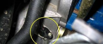
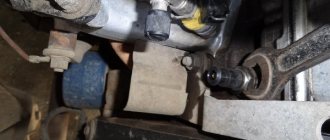
Device location.
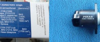
Each vehicle is equipped with only the appropriate equipment, designed for a certain number of shaft rotations and installed in the appropriate seat. The Chevrolet Niva speed sensor is installed on the gearbox.
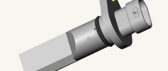
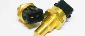
The sensor itself is a small steel or, more often than not, plastic device that is mounted in the shaft area. Inside the case there is a core that transmits impulses to a special controller responsible for displaying information on the instrument panel.
When carrying out work, it should be taken into account that the device can be quite fragile, so installation should be carried out with care.