A faulty idle speed controller leads to various engine malfunctions. One of them is when the engine stalls when the speed is reduced, which is fraught with an emergency situation. How to determine the malfunction of the IAC and replace it in the article.
Drivers often call the IAC sensor an idle speed sensor, which is completely wrong. The sensor “takes” readings and displays them on the screen (or device), and the regulator directly controls the operation of the engine. However, he is a sinner and I often call him that out of habit.
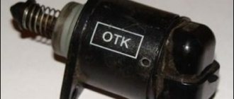
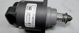
Typically, injection sevens have an IAC with article number 2112-1148300-04 (the last digit is the IAC version).
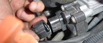
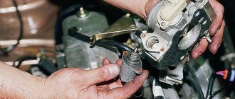
The idle speed sensor is installed on the injection VAZ 2107 in the lower part of the throttle valve on the right. You won't be able to replace it with a new one without removing it, but you will have to disassemble it a little. But more on that below, but first let’s look at the signs of a malfunction. Although I note that it is still possible not to remove the damper if you have a special screwdriver.
Replacing the idle speed sensor VAZ 2107 injector
When the cold came, somewhere in October.
When you are standing at a traffic light, sometimes the revs start jumping from 1500 to 500, and when you start moving everything is fine and may not happen again in a day, but it is extremely unpleasant. On the Internet, based on such symptoms, they say that the idle speed sensor is starting to fail. Which is located in the throttle valve.
The idle speed sensor is located at the bottom
When replacing there are no particular difficulties, we remove the throttle, connect the chip from the sensor, unscrew the two screws and take it out.
The most interesting thing is that it says two types of sensors can be installed from the Niva and from the Ten, after removing the inscription on it it was not visible, and after comparisons in the store I did not find any particular differences, so I bought it from the Ten.
New sensor on the bottom
I put everything in place, started it, the revs are high, turned it off, started it again, and everything works as it should, the revs are normal.
After two days there are no more problems with idle speed.
Disassembling and cleaning the unit
The tools for disassembling the carburetor will be the same as for dismantling. We perform the procedure in the following order:
- Place the product on a clean surface, unscrew the fasteners of the top cover and remove it.
| Carburetor designation | Fuel main system | Air main system | Fuel idle | Air idle | Accelerator pump nozzle | |||||
| I Kam. | II Kam. | I Kam. | II Kam. | I Kam. | II Kam. | I Kam. | II Kam. | fuel | bypass | |
| 2107–1107010; 2107–1107010–20 | 112 | 150 | 150 | 150 | 50 | 60 | 170 | 70 | 40 | 40 |
| 2107–1107010–10 | 125 | 150 | 190 | 150 | 50 | 60 | 170 | 70 | 40 | 40 |
The most common way to remove contaminants from inside a product involves disassembling it piece by piece, which not every car enthusiast can do. There is also a simpler option for cleaning the unit without disassembling it using special aerosols. The most popular are ABRO and Mannol.
Washing is carried out as follows:
- With the engine turned off and cooled down, dismantle the air filter housing and unscrew the solenoid valve.
Before you start repairing or adjusting the carburetor, you need to be sure that it is the problem. In addition, the unit must be periodically inspected and cleaned of contaminants that form both outside and inside the mechanism, which step-by-step instructions will help you with.
IDLE SPEED REGULATOR (SENSOR) VAZ 2107
In everyday life, the IAC is called a sensor, although it is not one. The fact is that sensors belong to measuring equipment, and regulators belong to executive equipment. In other words, it does not collect information, but executes commands.
PURPOSE
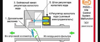
The IAC is a component of the fuel supply system of an engine with distributed injection, regulating the volume of air entering the intake manifold (receiver) when the throttle valve is closed. In fact, this is an ordinary valve that slightly opens the spare (bypass) air channel by a given amount.
IAC DEVICE
The idle speed control is an electric motor of a stepper design, consisting of a stator with two windings, a magnetic rotor and a rod with a spring-loaded valve (shut-off tip). When voltage is applied to the first winding, the rotor rotates to a certain angle. When it is fed to another winding, it repeats its movement. Due to the fact that the rod has a thread on its surface, when the rotor rotates, it moves back and forth. During one full revolution of the rotor, the rod takes several “steps”, moving the tip.
1 - valve; 2 — regulator body; 3 - stator winding; 4 — lead screw; 5 — plug terminal of the stator winding; 6 — ball bearing; 7 — stator winding housing; 8 - rotor; 9 - spring
OPERATING PRINCIPLE
The operation of the device is controlled by an electronic unit (controller). When the ignition is turned off, the IAC rod is pushed forward as much as possible, which is why the passage hole of the bypass channel is completely blocked, and air does not enter the receiver at all.
When the power unit starts, the electronic controller, based on data received from temperature and crankshaft speed sensors, supplies a certain voltage to the regulator, which, in turn, slightly opens the flow area of the bypass channel. As the power unit heats up and its speed decreases, the electronic unit through the IAC reduces the flow of air into the manifold, stabilizing the operation of the power unit at idle.
The operation of the regulator is controlled by an electronic control unit
When we press the accelerator pedal, air enters the receiver through the main channel of the throttle assembly. The bypass channel is blocked. To correctly determine the number of “steps” of the device’s electric motor, the electronic unit additionally uses information coming from the throttle position, air flow, crankshaft position and speed sensors.
When additional load occurs on the engine (turning on the radiator fans, heater, air conditioner, heated rear window), the controller, through the regulator, opens a spare air channel to maintain the power of the power unit, preventing dips and jerks.
WHERE IS THE IDLE CONTROL LOCATED ON THE VAZ 2107
The IAC is located in the throttle body. The assembly itself is attached to the rear of the engine intake manifold. You can determine the location of the regulator by the wiring harness that fits its connector.
The IAC is located in the throttle body
IDLE CONTROL IN CARBURETOR ENGINES
In carburetor power units of the VAZ 2107, idle speed is ensured using an economizer, the actuator of which is an electromagnetic valve. The valve is installed in the carburetor body and is controlled by a special electronic unit. The latter receives data on the number of engine revolutions from the ignition coil, as well as on the position of the throttle valve of the primary chamber of the carburetor from the contacts of the fuel quantity screw. Having processed them, the unit supplies voltage to the valve, or turns it off. The design of the solenoid valve is based on an electromagnet with a shut-off needle, which opens (closes) the hole in the idle fuel jet.
Setting the float chamber level
This is the first step in adjusting any carburetor. It is on this part that the consumption and stability of the engine will depend. The level must be at the nominal level set by the manufacturer, so it is very important to follow the technology.
Setting the fuel level in the float chamber: I - carburetor cover; 2 — needle valve seat; 3 - emphasis; 4 - needle valve; 5 - locking needle ball; 6 - valve needle pull-out fork; 7 — float bracket; 8 - tongue; 9 — float; 10 - gasket.
SIGNS OF IAC MALFUNCTION
Signs that the idle air control valve is faulty may include:
- unstable idling (the engine troits, stalls when the accelerator pedal is released);
- decreasing or increasing the number of engine revolutions at idle (floating speed);
- reduction in the power characteristics of the power unit, especially with additional load (turning on the heater fans, radiator fans, heated rear window, high beam, etc.);
- complicated engine starting (the engine starts only when you press the gas pedal).
But here it should be borne in mind that similar symptoms may also be inherent in malfunctions of other sensors, for example, throttle position sensors, mass air flow or crankshaft position sensors. In addition, if the IAC malfunctions, the “CHECK ENGINE” indicator lamp on the dashboard does not light up, and it will not be possible to read the engine error code. There is only one way out - a thorough check of the device.
CHECKING THE ELECTRIC CIRCUIT OF THE IDLE CONTROL CONTROL
Before moving on to diagnosing the regulator itself, it is necessary to check its circuit, because the reason that it stopped working could be a simple break in the wires or a malfunction of the electronic control unit. To diagnose the circuit, you only need a multimeter with the ability to measure voltage. The procedure is as follows:
- Raise the hood and find the sensor wiring harness on the throttle assembly.
- Disconnect the wiring harness block.
Each of the IAC pins is marked - Turn on the ignition.
- We turn the multimeter into voltmeter mode with a measurement range of 0–20 V.
- We connect the negative probe of the device to the ground of the car, and the positive one in turn to terminals “A” and “D” on the wiring harness block.
The voltage between ground and terminals A, D should be approximately 12 V
The voltage between ground and each of the terminals must correspond to the voltage of the on-board network, i.e. approximately 12 V. If it is less than this indicator, or is absent at all, you need to diagnose the wiring and electronic control unit.
Replacement
Diagnostics, cleaning and replacement of the throttle body is carried out after removing the throttle unit from the car.
The sensor is carefully removed from the dismantled unit and inspected. To check the performance of the dhx, use a tester switched to ohmmeter mode. Step by step diagnostic procedure:
- Set the measuring range on the tester to 0-200 Ohm.
- Attach the probes to the terminals, first on “A” and “B”, then “C” and “D”. The working element will show a value within the range of 50-53 Ohms.
- Take measurements between opposite pairs: “A” and “C”, then “B” and “D”. On a working unit, the instrument readings should tend to infinity.
If the electrical parameters are normal, the rod is measured - the overhang length should not exceed 22 mm.
If the rod is jammed, its size is increased, there are no optimal indicators of the multimeter, the part is changed. It is not advisable to repair the sensor.
DIAGNOSTICS, REPAIR AND REPLACEMENT OF IDLE CONTROL
To check and replace the regulator itself, you will need to dismantle the throttle assembly and disconnect the device from it. The following tools and resources will be needed:
- screwdriver with Phillips bit;
- slotted screwdriver;
- round nose pliers;
- socket wrench or socket 13;
- multimeter with the ability to measure resistance;
- calipers (you can use a ruler);
- clean dry cloth;
- coolant for topping up (maximum 500 ml).
DISASSEMBLY OF THE THROTTLE UNIT AND REMOVAL OF THE IAC
To remove the throttle assembly, you must:
- Raise the hood and disconnect the negative cable from the battery.
- Using a slotted screwdriver, hook the end of the throttle cable and remove it from the gas pedal pin.
- On the throttle block, use round pliers to disconnect the clamp on the throttle valve drive sector.
The fastener is detached using pliers or a screwdriver - Turn the sector counterclockwise and disconnect the cable end from it.
To disconnect the tip, you need to turn the drive sector counterclockwise - Remove the plastic cap from the cable end.
- Using two 13mm wrenches, loosen the cable fastening on the bracket.
To loosen the cable, you need to loosen both nuts - Pull the cable out of the bracket slot.
To remove the cable, it must be removed from the bracket slot - Disconnect the wire connectors from the IAC connectors and the throttle position sensor.
- Using a screwdriver with a cross-shaped bit or pliers (depending on the type of clamps), loosen the clamps on the coolant inlet and outlet fittings.
Remove the clamps. In this case, a small amount of liquid may leak out. Wipe off any spills with a dry, clean cloth. The clamps can be loosened with a screwdriver or pliers (round pliers) - In the same way, loosen the clamp and remove the hose from the crankcase ventilation fitting.
The crankcase ventilation fitting is located between the coolant inlet and outlet fittings - Using a Phillips-head screwdriver, loosen the clamp on the air supply pipe.
Remove the pipe from the throttle body. The air pipe is fixed with a worm clamp - Similarly, loosen the clamp and remove the hose for removing fuel vapors from the fitting on the throttle assembly.
To remove the fuel vapor exhaust hose, you need to loosen the clamp - Using a socket wrench or a 13mm socket, unscrew the nuts (2 pcs) securing the throttle assembly to the intake manifold.
The throttle assembly is attached to the manifold using two studs with nuts - Remove the throttle body along with the sealing gasket from the manifold studs.
A sealing gasket is installed between the throttle assembly and the manifold - Remove the plastic bushing that defines the air flow configuration from the manifold.
The plastic sleeve sets the air flow configuration inside the manifold - Using a Phillips-head screwdriver, remove the two screws securing the regulator to the throttle body.
The regulator is attached to the throttle body with two screws - Carefully remove the regulator, being careful not to damage the rubber O-ring.
A rubber sealing ring is installed at the junction of the IAC with the throttle assembly
VIDEO: REMOVAL AND CLEANING OF THE THROTTLE ASSEMBLY ON A VAZ 2107
HOW TO CHECK THE IDLE AIRCRAFT CONTROL
To check the IAC, perform the following steps:
- Turn the multimeter into ohmmeter mode with a measurement limit of 0–200 Ohm.
- Connect the probes of the device to terminals A and B of the regulator.
Measure the resistance. Repeat the measurements for terminals C and D. For a working regulator, the resistance between the indicated terminals should be 50–53 Ohms. The resistance between adjacent paired terminals should be 50–53 Ohms - Switch the device to resistance measurement mode with the maximum limit. Measure the resistance between contacts A and C, and after B and D. The resistance in both cases should tend to infinity.
- Using a caliper, measure the extension of the regulator locking rod in relation to the mounting plane. It should be no more than 23 mm. If it is greater than this indicator, adjust the position of the rod. To do this, connect one wire (from the positive terminal of the battery) to terminal D, and briefly connect the other (from ground) to contact C, simulating a pulsed voltage supply from the electronic control unit. When the rod reaches its maximum reach, repeat the measurements.
If the resistance value between the listed terminals does not correspond to the specified values, or the stem overhang is more than 23 mm, the idle air control regulator must be replaced. There is no point in trying to repair the device. In the event of a break or short circuit in the stator windings, and it is these faults that cause changes in the resistance at the terminals, the regulator cannot be restored.
The rod should be extended 23 mm
CLEANING THE IDLE CONTROL CONTROL
If the resistance is normal and the length of the rod is fine, but it does not move after connecting the voltage, you can try to clean the device. The problem may be that the worm mechanism that moves the rod is jammed. For cleaning, you can use a rust-fighting liquid such as WD-40 or its equivalent.
The liquid is applied to the rod itself where it enters the regulator body. But don’t overdo it: you don’t need to pour the product inside the device. After half an hour, grab the rod and gently twist it from side to side. After this, check its functionality by connecting the wires from the battery to terminals D and C, as described above. If the regulator rod begins to move, the device can be used again.
VIDEO: IAC CLEANING
HOW TO CHOOSE IAC
When purchasing a new regulator, it is recommended to pay special attention to the manufacturer, because the quality of the part, and, consequently, its service life depends on it. In Russia, idle air regulators for injection VAZ cars are produced under catalog number 21203–1148300. These products are almost universal, as they are suitable for the “Seven”, and all “Samara”, and representatives of the VAZ of the tenth family.
The VAZ 2107 came off the production line with standard regulators produced by Pegasus OJSC (Kostroma) and KZTA (Kaluga). IACs produced by KZTA are today considered the most reliable and durable. The cost of such a part is on average 450–600 rubles.
INSTALLING A NEW IDLE CONTROL
To install a new IAC you must:
- Coat the O-ring with a thin layer of engine oil.
- Install the IAC into the throttle body and secure it with two screws.
- Install the assembled throttle assembly onto the manifold studs and secure it with nuts.
- Connect the main hoses of the coolant, crankcase ventilation and fuel vapor removal. Secure them with clamps.
- Put on and secure the air pipe with a clamp.
- Connect the wire blocks to the regulator and throttle position sensor.
- Connect the damper drive cable.
- Check the coolant level and add it if necessary.
- Connect the battery and check the operation of the motor.
As you can see, there is nothing complicated either in the device or in the process of checking and replacing the idle air regulator. If it malfunctions, you can easily solve this problem without outside help.
Description of models
The first VAZ 2107 was standardly equipped with a DAAZ carburetor In Russia, they were modified to meet the needs of the local automobile industry. DAAZ products had simple assembly, which subsequently affected their price. The given carburetor model was characterized by maximum simplicity and made it possible to provide good acceleration characteristics to the car. Initially, the space in the engine compartment was created specifically for DAAZ.
The VAZ 2107 carburetor is a complex, high-precision device, consisting of two chambers, one of which - the first is equipped with a special mechanical damper drive. It can be installed on any domestic rear-wheel drive car. The volume of the model in question is 1.5 and 1.6 liters.
Gasoline consumption when using DAAZ increases noticeably. But this is consistent with the car’s speed indicators, which are also increasing. And this is especially important when overtaking.
Drawing our attention to the model - “Ozone” - it is worth noting that this is a more modified version of the standard DAAZ. The new optimized mechanism had better environmental performance. Thanks to this, “Ozone” received its environmentally friendly name. In addition, it consumed much less fuel than the previous version, so for such an economical car as the VAZ 2107, the Ozone carburetor was considered the most optimal option of all possible.
Replacing the idle speed regulator VAZ 2107 (injector)
A faulty idle speed controller leads to various engine malfunctions. One of them is when the engine stalls when the speed is reduced, which is fraught with an emergency situation. How to determine the malfunction of the IAC and replace it in the article.
Drivers often call the IAC sensor an idle speed sensor, which is completely wrong. The sensor “takes” readings and displays them on the screen (or device), and the regulator directly controls the operation of the engine. However, he is a sinner and I often call him that out of habit.
Typically, injection sevens have an IAC with article number 2112-1148300-04 (the last digit is the IAC version).
The idle speed sensor is installed on the injection VAZ 2107 in the lower part of the throttle valve on the right. You won't be able to replace it with a new one without removing it, but you will have to disassemble it a little. But more on that below, but first let’s look at the signs of a malfunction. Although I note that it is still possible not to remove the damper if you have a special screwdriver.
Features for injector and carburetor
The idle speed regulator (sensor) belongs to the fuel system of an internal combustion engine with distributed injection. The purpose of the part is to open the air pipe into the receiver when the throttle valve is closed within strictly defined limits.
Structurally, the IAC on the VAZ 2107 is an electric motor, which consists of a stator, a magnetic rotor and a spring-loaded rod mechanism with a locking tip. The ECU sensor controls the opening of the damper to a certain area.
For carburetor engines, a different solenoid valve operation scheme is used. The regulator is installed in the carburetor; it is based on an electromagnet with a locking part. When voltage is applied from the ECU, the valve releases passage in the fuel nozzle.
Signs of a VAZ IAC malfunction
Signs of a regulator malfunction vary, here are the main ones:
- the engine stalls when the gas pedal is released;
- poor engine starting;
- floating engine speed;
- increased speed.
It should be borne in mind that some symptoms of a broken IAC may coincide with a malfunction of other sensors: crankshaft position, throttle valve or mass air flow. Therefore, you can accurately determine its malfunction by taking some measurements yourself or using computer diagnostics.
How to check the XX regulator
Self-checking the serviceability of the IAC VAZ 2107 and other models consists of measuring the voltage at the connection block, checking the resistance between the sensor terminals and measuring the length of the rod.
The figure below shows a drawing of the idle air control device. I am citing it to better understand the necessary checks.
IAC connection
VAZ idle speed control device
As you can see, there are 2 windings on the sensor. This is a stepper motor, one winding of which extends the rod, the second winding retracts it. A break in these windings, a short circuit between turns or even windings indicates a malfunction.
The regulator cannot be repaired and if a malfunction is detected, it must be replaced.
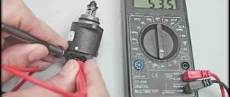
To check the regulator, you need a multimeter and a caliper (or ruler).
- First you need to disconnect the block and turn on the ignition and check for voltage at terminals A and D. It should be equal to the on-board network voltage. Its absence may indicate a malfunction of the ECU or the IAC power circuit. Sometimes a resistor breaks in the ECU and no power is supplied.
- Next, switch the multimeter to resistance measurement mode and look at the resistance between windings AB and CD. It should be about 52 ohms. In other positions there should be no resistance.
- Measure the length of the extended rod, it should be 23 mm. Deviation from it also indicates a malfunction.
How to replace idle air control
To replace the regulator, you can go in three ways:
- with complete disassembly of the throttle valve;
- partial;
- without removal.
I changed the regulator with complete disassembly, as I discovered clogged tubes, and a dropped plug rattled inside the receiver. When disassembling and cleaning I used carburetor cleaner. Although this is the same acetone and could have been saved.
Carburetor cleaner, if it is not needed under pressure, can be easily replaced with simple acetone
In the second option, the replacement is made without removing the tubes, but with removing the throttle. In this case, the air duct clamp is loosened, the throttle is unscrewed and, by moving it a little, removed from the studs. You need to turn it a little, this will give access to the sensor mounting bolt.
In the third option, you need a special screwdriver capable of unscrewing the sensor mounting screw. Typically, this is a flexible screwdriver for hard-to-reach places or an angled attachment for a screwdriver.
Necessary tool
To replace the sensor you will need:
- Flathead screwdriver.
- Crosshead screwdriver.
- Socket or open-end wrench size 13.
Replacing the idle speed sensor
To avoid getting burned, carry out the replacement on a cool or warm engine.
- disconnect the damper control cable;
- remove the block from the throttle position sensor;
- remove the block from the XX regulator;
- disconnect the coolant supply pipes from the throttle body;
- remove the crankcase ventilation pipe.
- disconnect the air supply pipe;
- pull the fuel supply hose to the throttle valve;
- unscrew the screws and remove the IAC.
Removed VAZ regulator
Removing the faulty regulator
Remove and replace the plug
Cleaned throttle body
Assembly is carried out in reverse order.
After replacing the regulator, do not start the engine immediately. Simply turn on the ignition, wait 10 - 30 seconds and turn off the ignition. After that you can start it. This time is necessary to calibrate the new idle air control ECU.
Ideally, when starting on a cold car, the speed should rise to 1500 rpm and drop to 800 as it warms up.
Preparing the machine
The preparation operations are not complicated and standard for any repair, but your personal safety, the time spent on maintenance and repair, as well as the quality of the work largely depend on their implementation. We prepare our VAZ2107 car for replacement as follows:
- We do car washing
- If possible, it is advisable to wash the outside of the car before work (you will get less dirty while working), including the bottom if necessary
- If the work (as in our case) is to be done in the engine department, then it should be washed there too
- The operation associated with washing the engine compartment is best performed in a non-automated car wash.
- Here, the engine compartment of your car will be washed by hand, having previously treated the outside of the body and the engine compartment with specific cleaning compounds.
- They will also remove dirt stuck in the wheel arches, as well as from the bottom of the body, using a directed jet of water under pressure, with drying completed.
Warning: When washing the engine compartment, you should protect the pads, sensors and other actuators of the fuel injection system from getting water. You should also avoid getting water on the starter and alternator. The sensors and contacts are wrapped with insulating tape or tape, the generator and starter are covered with plastic bags and the bags are secured so that they do not fly off. In any case, washing the engine compartment involves disconnecting the terminals from the battery. After washing, the above components and parts must be thoroughly dried; to do this, blow them with a stream of compressed air.
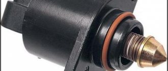
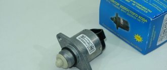
Which IAC should I choose?
I can recommend IAC from two manufacturers: Kaluga and Startvolt. Samarsky staged it, but there was some luck with him, it lasted for a year, just like with “PEKAR”. So which regulator is better can be checked with sellers, since they have information on the number of returns.
When purchasing, pay attention to the presence of quality control stamps and dates. Check the rod for play and absence of rotation. The presence of Chinese counterfeits on the market is quite large.
Whether the valve should have a wide or narrow cap seems to me to make no difference. Since the main role is played by the narrow part before expansion.
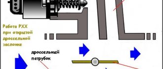
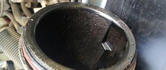
How does the idle air control control work?
As you can see in the photo, the valve opens the bypass channel when the engine starts and closes it as it warms up. The narrow part of the valve is involved in the work.
Preparing the carburetor for adjustment
VAZ 2107 - in the photo - the car is carburetor and is sensitive to fuel quality, therefore sometimes it needs to correct the capacity of channels and gaps
If the engine starts and runs stably at any speed and under any load, fine adjustment is unlikely to be needed. As a rule, this must be done in cases where the engine's fuel consumption exceeds the nominal values, when the engine is difficult to start, and dips appear in transient operating modes during sudden acceleration. Absence or instability of idle speed can also be treated by adjusting or cleaning channels and cavities.
Sometimes there are situations and clear symptoms that it is necessary to adjust the ignition timing or adjust the valves of the VAZ 2107, but the carburetor may be quite serviceable. Therefore, it is worth adjusting it only when there is confidence in the serviceability of the ignition system, the accuracy of setting the thermal clearances of the valves, after checking the functionality of the fuel pump, and good compression in each of the cylinders.
Adjustment may not bring results if the carburetor is clogged or has obvious mechanical problems or leaks. Therefore, a thorough inspection and assessment of the external condition of the device is necessary. Adjustment and configuration begin only when all these conditions are met.
The idle speed of the VAZ 2107 injection engine floats
VAZ 2107 is the latest model of the Zhiguli, available with rear-wheel drive. In essence, this is the “Five”, which has increased engine power, improved design and exterior. The car was produced with various engine sizes, ranging from 1.45 to 1.7 liters. Until 2006, the “Seven” had a carburetor engine, but during the transition to Euro-2, the designers developed and installed a forced fuel injection system, i.e. injectors.
With the introduction of injection engines, car enthusiasts felt positive changes in the operation of these cars.
All mechanisms are subject to wear and tear and fail over time. The forced injection system is no exception; during operation it acquires a number of malfunctions.
In VAZ 2107 cars, the engine sometimes stops working while idling. It happens that the engine stalls, but after starting it works properly. After some time this happens again. This means that the breakdown exists and will still have to be fixed. The reason is most likely in the throttle assembly, or more precisely in the idle air controller (IAC).
Jets and accelerator pump
A nozzle (injector) is a device for supplying fuel in a certain amount. The engine draws in air through the opening of a large diffuser. At the same time, fuel is dosed through the nozzle. The amount of air sucked in through the diffuser, as well as the amount of gasoline drawn in, depends on the engine displacement. Because of this, on engines with large volumes, carburetors with small jets are installed.
In order for the jet to produce a normal fuel assembly, not lean, it is necessary to find a carburetor that was initially designed for a certain engine volume or as close as possible to it. First, select the fuel and then the air jet. They are selected for the first camera, then the second camera is configured.
The accelerator pump is necessary to supply additional fuel when the throttle is opened, this provides more efficient acceleration. The pump operates through a special cam mechanism. On engines with Solex, you need to install the largest possible cam for the accelerator pump.
PURPOSE AND DEVICE OF IDLE CONTROL.
The idle speed regulator is designed to regulate the amount of atmospheric air entering through the bypass channel (bypass) into the suction manifold when the engine is idling. The main channel is closed by the throttle valve.
The regulator is a DC electric motor. It has two windings on the stator and a rotor with permanent magnets. The rotor is connected to the rod by a lead screw. At the end of the rod there is a valve that closes the hole in the bypass. Power is supplied either to the first or to the second stator winding. At the same time, the rotor rotates in one direction and then in the other, extending or retracting the rod and the valve with it using a screw.
OPERATING PRINCIPLE OF IAC.
SPVT (Forced fuel injection system) has its own “brain”, which receives all the information from the sensors, processes it and issues commands to the actuators for the optimal functioning of the internal combustion engine (ICE). This “brain” is called a controller or ECU (Electronic Control Unit). IAC refers to the actuators controlled by the controller.
At the moment of start-up, the regulator opens a hole in the bypass. Air enters the suction manifold through it. The engine starts running. As the engine warms up, the valve closes, reducing the air supply. The speed is stabilized to a minimum.
When the throttle valve is opened, the main flow of air is supplied to the engine through the main channel. In this case, the regulator closes the hole in the bypass. To smoothly control the idle air control, the ECU receives additional information from sensors: throttle position, air flow, crankshaft position and tachogenerator.
When additional loads on the engine arise (turning on a radiator fan, heater, etc.), the regulator opens a hole in the bypass. This makes it possible to maintain power and prevent engine failures.
Tools and equipment for work
To carry out maintenance work you will need:
- A set of standard keys;
- Screwdrivers;
- Pliers;
- Rags;
- Carburetor cleaner (“Carb Cleaner” or equivalent);
You will also need a repair kit for the carburetor. Various types of repair kits are available, some of which include only gaskets, while others include all parts (jets, screws, emulsion tubes, etc.). It is better to purchase a complete set.
Since the carburetor consists of many small parts, disassembling it into its component parts, washing and troubleshooting and tuning is carried out in stages so as not to lose sight of anything.
The principle of operation of the carburetor is simple. Its task is based on creating an air-fuel mixture, mixing air and fuel in the required proportions, after which this mixture enters the combustion chamber, where it is ignited. The “Seven” carburetor includes the following devices that ensure distribution of the fuel mixture:
- XX engine support.
- Acceleration pump.
- Maintain a stable fuel level.
- Econostat system.
- Support for starting and warming up the internal combustion engine.
- The main metering chamber, where there are air and fuel jets, a diffuser, a well, a VTS sprayer, and an emulsion tube.
After adjustment, noise and vibration decreased significantly. The engine runs smoothly and starts quickly. The power has increased and it picks up speed better. Fuel consumption has noticeably decreased.
UNSTABLE OPERATION OF INJECTION ENGINE.
Engine instability can be due to a failure in any system. Either:
- ignition;
- fuel supply;
- electronic control unit
- wear of moving parts and engine components.
To understand this, it is necessary to check the performance of systems using the elimination method. Let's look at an ECU as an example.
The engine is warmed up, but vibration and increased speed are felt during operation. Perhaps this is an accumulation of errors in the controller memory. To reset them, you need to turn off the engine and turn off the “mass” for 15 minutes. After that, start the engine. If there are no changes in engine operation, then the reason is in the ECU sensors.
When any of the sensors does not work, the ECU has to rely only on the data from the working devices. This is not enough for normal management of SPVT. The engine does not work correctly:
- Unstable crankshaft speed.
- Increased gasoline consumption, highly enriched mixture.
- There is black smoke on the exhaust.
- Soot or soot on spark plug electrodes.
This occurs due to a lack of data entering the control unit, such as:
- air flow;
- amount of oxygen in exhaust gases;
- throttle position;
- crankshaft position;
- temperatures;
- speed;
- or IAC failure.
To check the functionality of the sensors, you need to disconnect the wire connectors one by one and observe how the internal combustion engine operates. If there are no changes, then the device that is turned off has failed.
Most often, malfunctions occur in the idle air regulator.
Important adjustment points
After the installed structural element has reached its optimal position, it is necessary to press the gas pedal: the motorist must check the functionality of the motor, which will “raise” the crankshaft speed without interruption. At the same time, there should be no sudden damping of the engine after the pedal is released. If there are negative aspects, you will have to re-adjust the carburetor.
The CO content in the exhaust gases of the power unit must also be checked; according to the rules, after such manipulations it should decrease. With ideal performance of all components, CO should fluctuate within 1.5%.
When the screws do not help normalize the speed, the car owner will have to additionally check the power unit, since such moments indicate that the fuel “goes” to the mixing chamber, bypassing the idle system. In this case, you need to pay attention to the carburetor solenoid valve to close it. At the same time, you should measure the diameter of the nozzle hole, which is sometimes larger than necessary.
Source
SIGNS OF IAC MALFUNCTION.
There are several of them. They are all noticeable.
- Unstable engine speed at idle.
- Floating engine speed.
- When the engine is loaded, power drops sharply.
- Until you press the gas pedal, the internal combustion engine will not start.
- When you release the gas pedal, the internal combustion engine stalls.
- High idle speed.
The above symptoms may also occur in case of malfunctions of other SPVT equipment. To be convincing, it is necessary to confirm the inoperability of the IAC by conducting diagnostics at a service station, or independently.
CHECKING THE ELECTRICAL IAC CIRCUIT.
What can you do yourself when checking the electrical circuit of the idle speed control of a VAZ 2107? Measuring the voltage at the connection block to the control unit and measuring the resistance of the regulator motor windings. To measure you need to have a tester. The diagnostic procedure is given below:
- Disconnect the block with the wiring harness from the regulator. It is located on the throttle assembly.
- Turn on the ignition.
- Set the tester to voltage measurement mode in the range from 0 to 20 volts.
- Connect the probe from the tester with a minus sign to the ground of the car.
- Connect the probe from the tester with the “plus” sign in turn to terminals “A” and “D” on the harness block. The voltage between ground and terminals should be 12 volts. If there is no voltage, the controller may not be corrected.
- Next, move the tester to the resistance measurement position. Measure the resistance of the first winding between terminals “A” and “B”. Measure the resistance of the second winding between terminals “C” and “D”. There should be 52 ohms on both windings. In other variations of measurements between the terminals, the device should indicate an open circuit. If the tester shows the opposite, then the electric motor is faulty.
IAC malfunction.
The electric motor is not the only component in the regulator that can break; there are a number of other breakdowns:
- oxidation of connector contacts, broken wires;
- contamination of the rod, preventing movement;
- the o-ring is torn;
- wear of the screw thread on the rod.
Of the above breakdowns, the most common is contamination of the rod. If during operation the throttle assembly has not been maintained for a long time, carbon deposits on the regulator rod are possible. To remove dirt, you need to remove the IAC and rinse with acetone.
The stem needs to be cleaned periodically. Otherwise, the load increases, which can damage the ECU. Then you will have to contact service station specialists.
Problems in the mass air flow sensor - mass air flow sensor.
The mass air flow sensor is located in the air duct between the throttle valve and the air purification filter. It shows the volume of air entering from the atmosphere into the suction manifold. Based on these data, the control unit calculates the amount of fuel required for the current operating mode of the internal combustion engine.
If the sensor is faulty, the “Check Engine” light on the panel lights up. In parallel with this, a number of signs of failure are possible:
- Fuel consumption has increased.
- Idle speed is increased.
- The dynamics of the car are disrupted due to a decrease in power.
- It is impossible to start the internal combustion engine, even when “hot”.
- The speed changes at any throttle position, even under engine load.
Such sensors are not repaired, but replaced. Therefore, you need to make sure that this is the reason. Often the cause may be contamination of the platinum thread inside the device; it can be cleaned. Or the cause of air leakage through a damaged air duct.
Air leaks through cracks in hoses and seals.
There are many places where excess air can enter the suction manifold, bypassing the mass air flow sensor. The fuel mixture becomes leaner, the speed decreases, and the power drops. The ECU tries to correct these errors. A failure occurs in the system, the speed and “thrust” do not correspond to the specified parameters. The "Check Engine" warning light on the dashboard does not light up. The conclusion from this is that the sensors are working, but the internal combustion engine is sucking in air somewhere.
There are several places for air leaks that you should pay attention to, these are:
- the manifold with its gaskets, all kinds of joints, gaskets under the equipment attached to the manifold;
- vacuum brake booster and its hoses:
- throttle body;
- vacuum pipes.
After eliminating these shortcomings, the power unit will operate normally.
Other reasons.
A car is a complex engineering structure. During operation, its units, components, systems, and blocks are subject to wear. And it is impossible to describe all combinations of breakdowns.
Here are some reasons for the internal combustion engine not working properly:
- The ignition system has many of its own “sores”.
- Nozzles requiring professional care.
- Low quality gasoline.
- Presence of water in the fuel tank.
- Fuel and air filters are clogged.
- Other.
In each case it is necessary to understand, identify cause and effect. If you can’t do it yourself, you should contact a service station specialist.
In this article, “Why do idle speeds fluctuate on a VAZ 2107 injection engine,” the emphasis is on the breakdown of the XX Regulator. If it is broken, it can hardly be repaired. It's better to change it. It’s not difficult to do it yourself, having a new IAC and a minimum of tools.
How to set up a Solex carburetor
This can be done without removing the device from the car. However, in some cases you have to do this to configure some parameters. Both options are considered further. How to adjust the carburetor directly on a car?
Setting levels in float chambers
Before making adjustments, start the engine and warm it up for 10 minutes, then turn off the ignition. The following actions:
- disconnect the fuel hose from the device;
- unscrew the 5 screws securing the carburetor cover;
- disconnect the choke control cable;
- lift the lid evenly and slowly so as not to deform the floats;
- Using a caliper, measure the distance from the plane of the cover to the surface of the fuel - it should be 23-25 mm;
- if the value is incorrect, bend the float tongue in each of the chambers in the desired direction;
- At the same time, clean the cameras from dirt;
- put the cover in place, then you need to install the dismantled elements.
Adjusting the needle
Place the Solex lid on a horizontal, flat surface. Now, by bending the metal “petals”, adjust the stroke of the valve needle, which should be equal to 2 mm. At the same time, check the tightness of the fuel valve. To do this, take a rubber bulb, insert it into the tip of the inlet fitting and squeeze so that it is deformed. At the same time, close the return fitting channel very tightly with your finger. When you turn the lid over, the bulb will become normal in shape, which indicates that the valve is opening, i.e., working.
Idle speed setting
Start the car and warm up the engine to operating temperature of 85-90 degrees, and then turn it off. Further:
- at the bottom of the Solex, find the mixture quality adjusting screw and screw it in completely (but not with excessive force, so as not to strip the thread);
- “back up” by unscrewing the screw 4-5 full turns;
- start the engine, press the choke handle all the way;
- by rotating the quantity screw, achieve stable operation of the internal combustion engine at minimum speed (according to the tachometer this is 700-1100 rpm);
- screw the quality screw back in until the engine begins to try to stall, and unscrew the hardware 1-1.5 turns;
- tighten the quantity screw until it reaches 900 rpm - if the motor starts to work unstably, slightly unscrew the quality screw again.
What to do if the motor does not respond to the rotation of the propellers
It’s quite a common situation: you turn the quality or quantity screw, but the engine does not change speed. The reason for this phenomenon is poor flow of gasoline into one of the idle channels (ICH). At the same time, the hardware responsible for the quality of the mixture simply does not have time to shut off the gasoline supply. This is due to:
- incorrectly sized jets: check their diameter and install standard products;
- the seat for these parts is loose;
- The XX solenoid valve (the “barrel” or cylinder to which the electrical wire fits) or the plug in its place is not screwed tightly enough.
How to set the transition mode
It is he who is “responsible” for the failure of the accelerator pedal when it is pressed sharply. Here the main role is played by the hole located above the throttle valve (spout). After sharp pressure on the gas, an additional portion of gasoline begins to be sucked in. In order to avoid failures, it is necessary to carefully select the XX jet and the spout that sprays fuel. Work algorithm:
- start the car and press the choke handle all the way;
- gently press the gas pedal: if there are dips, the nozzle located in the first chamber is to blame; with a normal set of revolutions, proceed to the next point;
- sharply press the accelerator: if there is a failure, you need to select the spout (optimal dimensions 40*40) and the jet (39-40).