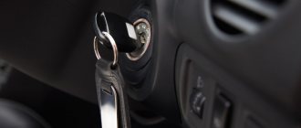
When getting into a car, any driver turns the key in the ignition to start the engine. This simple action ensures that the starter receives voltage from the power source, as a result of which the engine crankshaft begins to turn and the engine starts. If a breakdown occurs with the ignition switch, further operation of the vehicle becomes impossible. However, many problems can be fixed with your own hands.
- Purpose and design
- Connection diagram
- Description
"The lock
- contact Group
- Ignition switch problems
The key won't turn
Video: replacing a lock if the key breaks
- How to remove the lock
Video: how to remove the lock on a VAZ 2106
- Video: repairing the ignition switch on a “classic”
Ignition switch VAZ 2106
At first it may seem that the ignition switch of the VAZ 2106 is an insignificant detail. However, if you look at it, the mechanism is an integral part in any car, since it starts the engine and powers the electrical network. In addition to supplying voltage to the starter, electricity from the lock is supplied to the ignition system, devices that allow you to control certain vehicle parameters, etc. While the vehicle is parked, the device de-energizes systems and devices.
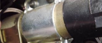
The ignition switch provides voltage to the starter and the vehicle's on-board network
Purpose and design
If we describe the purpose of the ignition switch in simple words, then this mechanism prevents the battery from being discharged through the on-board network and provides voltage only when necessary, i.e. during operation of the car.
The main elements of the ignition switch are: 1. - locking rod; 2 - body; 3 - roller; 4 - contact disk; 5 — contact sleeve; 6 - block
The ignition switch on the VAZ Six consists of the following elements:
- locking rod;
- frame;
- roller;
- contact disk;
- contact sleeve;
- block.
There are many wires connected to the lock mechanism. They are supplied from the battery and connect all electrical appliances installed in the car into a single electrical circuit. When the key is turned, a circuit is closed from the “-” terminal of the power source to the ignition coil. The current passes through the wires to the ignition switch, and then is supplied to the coil and returns back to the positive terminal of the battery. When current flows through the coil, a voltage is generated in it, which is necessary to create a spark at the spark plugs. As a result, when the key closes the ignition circuit contacts, the engine starts.
Connection diagram
The ignition switch is connected to the electrical circuit using wires with connectors at the ends. If the wires are connected to the mechanism using a chip (large round connector), then there should be no problems with the connection.
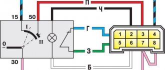
Wires to the lock can be connected individually or via a connector
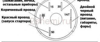
If the wires are connected separately, you must adhere to the following connection sequence:
- pin 15 - blue with a black stripe (ignition, interior heating and other devices);
- pin 30 - pink wire;
- pin 30/1 - brown;
- pin 50 - red (starter);
- INT — black (dimensions and headlights).
The ignition switch is connected to the electrical circuit using wires with connectors
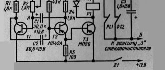
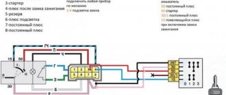
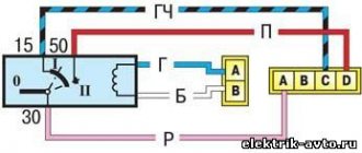
Below is the electrical diagram for connecting the lock:
Lock connection diagram: 1. - battery with negative terminal connected to ground; 2. - electric starter with output 50 from the ignition switch through the starting relay; 3. - generator; 4. — fuse block; 5. — ignition switch; 6. - start relay
Also check out the electrical diagram of the VAZ-2107: https://bumper.guru/klassicheskie-modeli-vaz/elektrooborudovanie/elektroshema-vaz-2107.html
Description
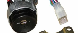
The ignition switch of the VAZ 2106 is made in the shape of a cylinder and consists of an electrical (contacts) and a mechanical (core) part. The mechanism also has a protrusion for fixing the steering wheel. On one side of the device there is a recess for the key, on the other there are contacts for connecting electrical wires. The two parts of the lock are connected to each other by means of a leash.
The ignition switch provides not only rotation of the contact group rotation mechanism, but also locks the steering wheel when the key is removed from the lock. Locking is possible due to a special rod, which, when turning the key to the right, partially enters the device body. When the key rotates counterclockwise, the element extends, and when it is removed, the part enters a special hole in the steering column. The locking mechanism is accompanied by a loud click when the key is removed.
"The lock
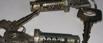
Since each key has its own tooth shape, this is an additional measure of protection against theft. Therefore, if you try to start the engine with another key, it will not be possible.
The lock cylinder is designed to work with only one key, which is an additional measure of protection against theft
contact Group
The contacts of the VAZ 2106 ignition switch have the form of a washer with leads for connecting electrical wiring. On the inside of the washer there are conductive contacts of these terminals, as well as a movable element that rotates under the influence of the lock mechanism. When the position of this element changes, certain contacts are closed, thereby providing power to the terminals of the product in question, connected to the closed coins.
The ignition switch contact group provides connection of certain terminals to supply power to the starter and other electrical devices
How does it work
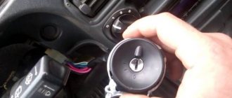
The ignition switch of the “six” is located in the car interior to the left of the steering column and is hidden by decorative elements. On the driver's side, the mechanism has a key hole. There are several marks on the front surface of the lock - 0, I, II and III. Each of them has its own purpose.
The “0” mark is a position that ensures that all devices powered by the ignition switch are turned off; the key can also be removed in this position.
Electrical devices such as a brake light, a cigarette lighter, or interior lighting operate regardless of the position of the key in the lock, since they are constantly supplied with battery power.
Mark I - in this position, power is supplied to the on-board network. Voltage is supplied to the headlights, dashboard, and ignition system. In this case, the key is fixed and there is no need to hold it.
Mark II - in this position of the lock, voltage from the battery begins to flow to the starter to start the power unit. In this case, there is no locking, so the driver holds the key until the engine starts. As soon as the engine starts running, the key is released and it takes position I.
Mark III - parking. In this position, all electrical devices connected to the on-board network are de-energized, and a latch is inserted into the hole in the steering wheel column, which prevents the theft of the vehicle.
Find out about the malfunctions of the VAZ-2106 instrument panel: https://bumper.guru/klassicheskie-modeli-vaz/elektrooborudovanie/panel-priborov/panel-priborov-vaz-2106.html
There are marks on the lock, each of which has its own purpose.
Preparatory work
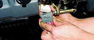
Before proceeding directly to removing the ignition switch, it is necessary to perform a number of actions. First of all, you need to disconnect the negative battery. This way, all electrical systems will be de-energized, and you can safely begin work. After this, it is advisable to remove the covers on the steering column. This is not difficult to do - you just need to have a screwdriver with you and apply a little effort.
After the casing has been dismantled, it is advisable to clean the surface of the lock from various types of contaminants. If you look closely, you can find the wiring harness block. It needs to be disconnected from the contacts of the VAZ ignition switch. All work must be done carefully so as not to damage the wiring. As for the tools, we only need a flat-head and Phillips screwdrivers, as well as a multimeter to check the functionality of the device. Now you can proceed directly to removing the device.
Ignition switch problems
Problems are possible with both the mechanical and electrical parts of the device.
The key won't turn
One of the lock malfunctions is a problem with the key, when it turns tightly or does not turn at all. Quite often the situation ends with the key breaking, as a result of which part of it remains inside the mechanism. A solution to the problem of a jamming lock can be the use of a penetrating lubricant, for example, WD-40. But do not forget that this is just a temporary solution and the switch will still have to be replaced in the near future.
Video: replacing a lock if the key breaks
Devices do not function
If such a problem is observed when the key is turned in the lock, but the instruments on the dashboard do not show “signs of life,” this may indicate damage to the contacts of the mechanism, as a result of which they do not fit together tightly enough. The malfunction is solved by replacing the contact group or simply by cleaning the contacts with fine sandpaper. It is advisable to check how tightly the connectors fit on the contacts - they may need to be tightened with pliers.
The starter does not turn on
If there is a problem with the lock, problems with starting the starter may also occur. The reason is damage to the switch contacts or failure of the contact group. As a rule, the malfunction is typical for the contacts that supply power to the starter. The problem manifests itself as follows: the starter does not start or it takes several attempts to turn it on. To determine whether there is indeed a fault in the contacts, you can check the voltage at the terminals using a test lamp or multimeter.
If it is discovered that the contacts have become unusable, it is not necessary to completely change the lock - you can only replace the washer with the contacts.
More information about starter repair: https://bumper.guru/klassicheskie-modeli-vaz/elektrooborudovanie/starter-vaz-2106.html
Replacing the contact group
Sometimes there is no need to completely change the lock mechanism. It is enough just to change the contact group.
It is located on the back of the mechanism. Attached to the body with a spring ring. You can try to remove it by hand or using a screwdriver.
We film the group itself. It consists of two plastic rings that have built-in current-carrying tracks. There is a spring inside the ring.
Over time, carbon deposits form on these tracks, which leads to failure. There is no point in messing around with this soot. It's easier to buy a new group in the store. Its cost for a VAZ 2106 does not exceed 50 rubles.
Please note that there are different models. On some, the starter contact is attached so that when you turn the key, the contact bends. This leads to quick breakdowns. It is better to choose a model on which the contact is rigidly installed.
Installing a new part is easy. Alternately move the wires from the previous part, choosing the correct contacts. Place the key in the zero position, turn the top of the group to the left until it stops and insert it into the lock. Make sure that the blade inside the body fits into a special groove. Snap and slide on the snap ring.
Installing the "Start" button
Some VAZ 2106 owners install a button for ease of starting the engine. It is connected via the starter power circuit to the break in the red wire, which goes to terminal 50 of the ignition switch. In this case, the engine starts as follows:
- The key is inserted into the lock.
- Turn it to position I.
- The starter is started by pressing the button.
- When the engine starts, the button is released.
To stop the power unit, you must turn the key counterclockwise. A slightly different option for connecting the button is also possible, so that with its help you can not only start the engine, but also turn it off. For these purposes you will need the following parts:
- headlight relay RS 711;
- starter relay 113.3747–10 or 90.3747–10.
In order to turn off the engine, the button must be connected in a slightly different way.
According to the diagram, when the button is pressed, power is supplied to the headlight relay, and after the contacts are closed, to the starter. When starting the power unit, the button is released, thereby opening the contacts of the starter relay and breaking its power circuit. If you press the button again, the contacts of the switching device open, the ignition circuit is broken and engine operation stops. The second option for using the button is called “Start-Stop”.
Even a car owner who is encountering such a problem for the first time can replace or repair the ignition switch on a VAZ 2106. To carry out the work you will need a minimum of tools and following step-by-step instructions. The main thing is to connect the wiring to the lock in accordance with the diagram.
Mechanical part
Often, mechanical failure of the ignition switch is provoked by:
- tight turning of the ignition key;
- jamming in one of the positions. As a rule, such a problem leads to a broken ignition key, which, in turn, requires additional expenses for purchasing a new part.
Basically, these problems arise due to poor assembly of the ignition switch from unscrupulous manufacturers. So that the product does not have to be changed frequently, you need to install a reliable and durable part.
How to connect wires: diagram
To connect to wires, the terminal block has the following pins:
- «15»;
- «30»;
- «30/1»;
- «50»;
- "INT".
A blue cable must be installed on terminal “15”, and it must be double. At “30/1” there is a brown version, at “30” - pink, at “50” - red or purple, at the “INT” terminal - black and always double. Terminals “30” and “50” are responsible for starting the starter, which, if the lock fails, can be connected to start the engine in order to successfully get to a service station or auto parts store.
Typically, the terminal block box will provide instructions that clearly explain how to connect the cables. By following all the rules exactly, you can do this work yourself, without contacting technical service. Those who find it difficult to understand the instructions will still have to turn to the experts so as not to harm their own car, since one wrong action can damage certain elements of the ignition system.
Malfunctions
The design of the lock is quite simple and reliable, but the lock may well break. There are only two malfunctions that can happen to this element: mechanical and electrical.
A mechanical failure includes a problem with the secretion. Due to debris that gets inside the secretion and moisture, corrosion is formed, which prevents the movement of moving elements inside the secretion. As a result, the lock begins to jam when you turn the key, jams, or stops rotating altogether. This problem can be eliminated by pouring WD-40 or at least brake fluid inside.
An electrical fault is the burning of the nickels of the contact group. Because of this, there will be no or insufficient contact between the runner and the nickel. Electrical appliances on the car will not work, and there may be no power supply to the starter. If the burning was minor, then you can try to restore the functionality of the lock by cleaning the nickels with a diamond file, followed by wiping with alcohol or gasoline. But if the nickels are badly burnt, then you will need to either change the contact group or the lock assembly.
Replacing the ignition switch:
Removal: 1) At the beginning of the operation, remove the upper and lower casing from the steering column. (For information on how to remove the cover, see the article: “Replacing the instrument panel”)
2) Next, using a marker or something else, mark the wires that are connected to the back of the lock, and only then disconnect all the wires.
3) Next, using a Phillips screwdriver, unscrew the two lower screws that secure the ignition switch.
4) Then insert the key into the lock cylinder and turn it to position “0”, thereby disabling the anti-theft device that locks the steering wheel. At the same time, use a thin awl or screwdriver to press the latch that holds the lock in place... (Continued in point 4)
5) And then pull the key to remove the lock from the bracket.
Note! Installing a new lock occurs in the reverse order!
Checking the ignition switch elements for functionality:
1) To check the correct closure of the contacts at different key positions, do the following:
• First, take the voltage from the “AKB - Rechargeable Battery” and the generator and thereby apply it to the contacts in accordance with the table:
Note! The free “INT” plug, just so you know, is intended only for connecting a radio receiver, and contacts “30/1” and “30” are used to connect wires coming from the battery and generator as mentioned above!
2) Now check how the steering wheel lock works, also known as an anti-theft device, for this:
• Insert the key into the lock and turn it to position “III”, and pay attention to the locking rod (Indicated by the number “1”), which at this moment should extend.
• Then turn the key in the lock to position “0” and again turn your attention to the locking rod, which at this moment should sink.
Note! And also take note that the key must be removed from the lock cylinder only when it is in position “III”!
Replacing the contact part of the lock:
1) First, remove the ignition switch from the car.
Note! In fact, it is possible to remove and install the contact part of the lock even if the ignition switch is installed in its place, but only in this case, replacing the contact part will be much more difficult than with the lock removed!
2) Then pry the retaining ring through the hole in the end of the case under the number “2” (see “photo”), and after prying the ring, carefully remove the contact part from the case.
Note! When reinstalling the contact part, install it so that the wide protrusion under the letter “A” in the photo above fits into the wide groove that is present on the lock body. And after installing the contact part, check that the locking rod “under the number 1” is located next to the plugs “15” and “30” on the contact part!
Functionality check
Diagnosis of the correctness of the work performed is carried out as follows:
- Terminals are connected to the battery.
- The key is inserted into the 3Z in mode 0. If all contact components are connected correctly, then no car system will be activated.
- Then the key is set to mode I. In this position, power is supplied to the control panel, generator set, optics and sensors. The windshield washer system and wipers, warning lights and power windows, if installed in the car, are also turned on. It is necessary to check the operation of each node.
- At the next diagnostic stage, the key is moved to position II. Electricity is supplied to all the systems described above, but the starter device is also activated.
If the ignition switch on a VAZ 2106 is connected correctly, the locking rod of the locking mechanism will extend and disengage when the key is moved from 0 to I.
Operating principle
So, the ignition switch on the VAZ-2101 is an element located in the cabin near the steering column. The entire lock structure is hidden under the decorative trims of the column, so from the driver's side the lock looks like a large round washer with a slot in the center.
Label “0” is the position in which all electrical appliances powered by the lock are disconnected from power. It should be noted that some of the equipment (interior lighting, brake light, cigarette lighter) do not depend on the position of the key in the lock; they are constantly powered by the battery. In this position the key can be removed from the lock.
Mark “I” - the position of the lock at which electricity is supplied to the on-board network. In this position, control and measuring instruments, light and sound alarms and headlights, the ignition system and a number of other electrical appliances receive power. This position is fixed, and when moving the key to it, it is not necessary to hold it.
Mark “II” is the position at which voltage begins to be supplied to the starter to start the engine. This position is not fixed, that is, the driver moves the key to this position and holds it to start the engine. After starting, the key is released and, under the action of a spring, it returns to position “I”.
Position “III” is parking. In this position, all electrical appliances are de-energized, and a lock is inserted into the groove of the steering column, which is an anti-theft device for the car.
It should be noted that the lock positions do not follow each other. So, to move the key to positions “I” and “II”, it must be rotated clockwise from “0”. And to set position “III”, the key is turned counterclockwise from “0”.