Tighten the engine bolts correctly
In the table below we have indicated the tightening torques for all threaded connections on the VAZ-2112 engine.
Tightening torque of threaded connections (table)
| Detail | Thread | Tightening torque, N m (kgf m) |
Measuring tool
Despite the fact that performing work according to the tightening rules requires a special approach, such a procedure will not take a lot of time.
The only thing required to perform such work is a torque wrench.
This wrench is used to measure the tightening torque.
You can get such a tool in any store, but its price is often steep and can sometimes reach 2,000 rubles.
Purpose
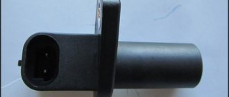
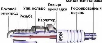
The crankshaft pulley serves to transmit rotation from the crankshaft to such important vehicle components as the generator, power steering and air conditioning. In addition to this function, in the injection engine there are special teeth on the damper-type pulley, which are read by the crankshaft sensor.
This is one of the most important indicators for the electronic motor control system, which is responsible for the correct operation of the entire unit.
If it fails (beating and deformation, cracks and tears), the VAZ crankshaft pulley will most likely need to be replaced. This part of the car can be repaired, but in very rare cases (if minor defects are detected).
It is not necessary to go to a specialized car workshop; if you have free time and skillful hands, you can do the replacement yourself, which will not only save money, but also increase your self-esteem.
Homemade torque wrench (as a last resort)
Homemade. It’s designed roughly like this, but you won’t be able to tighten it properly with such a device!
As a last resort, you can use a tool that you can assemble with your own hands.
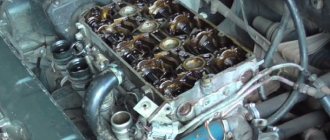
The internal combustion engine structurally has a large number of associated parts, which experience significant loads during operation of the internal combustion engine. For this reason, assembling a motor is a responsible and complex operation, for the successful implementation of which the technological process must be followed. The performance of the entire power unit directly depends on the reliability of fixation and the accuracy of fit of individual elements. For this reason, an important point is the accurate implementation of the calculated interfaces between mating surfaces or friction pairs. In the first case, we are talking about attaching the cylinder head to the cylinder block, since the cylinder head bolts must be pulled with a strictly defined force and in a clearly designated sequence.
As for loaded rubbing pairs, increased demands are placed on the fixation of connecting rod and main plain bearings (main and connecting rod bearings). After engine repair, during the subsequent assembly of the power unit, it is very important to maintain the correct tightening torque of the main and connecting rod bearings of the engine. In this article we will look at why it is necessary to tighten the bearings with a strictly defined force, and also answer the question of what is the tightening torque for the main and connecting rod bearings.
Read in this article
VAZ 2110 tightening the hub nut
4.2.3. Replacing the hub bearing
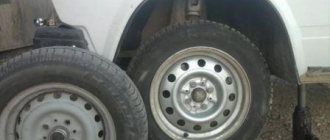
The hub is equipped with a double-row ball bearing, which does not require adjustment or lubrication during operation.
If, when swinging the suspended wheel, play or noise appears while driving, the hub bearing may have failed.
If there is increased play in the wheel, loosen the hub nut and check its tightening torque. If the torque is less than required, try tightening the nut to the required torque and lock it. If there is no play, the bearing will be able to work for some more time.
If there are no mandrels, you can use the rings of the old bearing. To press in the wheel bearing, use the appropriately sized mandrels from the kit.
What are plain bearings
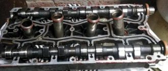
To better understand why engine bearings need to be tightened to a certain torque, let's take a look at the functions and purpose of these elements. Let's start with the fact that these sliding bearings interact with one of the most important parts of any internal combustion engine - the crankshaft. In short, the reciprocating motion of the piston in the cylinder is converted into rotational motion precisely thanks to the connecting rods and crankshaft. As a result, torque appears, which is ultimately transmitted to the wheels of the car.
The crankshaft rotates constantly, has a complex shape, experiences significant loads and is an expensive part. To maximize the service life of the element, connecting rod and main bearings are used in the crankshaft design. Taking into account the fact that the crankshaft rotates, as well as a number of other features, conditions are created for this part that minimize wear.
For the manufacture of liners, softer materials are used compared to those from which the crankshaft itself is made. The liners are also additionally coated with an anti-friction layer. Lubricant (motor oil) is supplied under pressure to the place where the liner is connected to the crankshaft journal. The specified pressure is provided by the oil pump of the engine lubrication system. In this case, it is especially important that there is the required clearance between the crankshaft journal and the plain bearing. The quality of lubrication of the rubbing pair, as well as the engine oil pressure in the engine lubrication system, will depend on the size of the gap. If the gap is increased, then the lubricant pressure decreases. As a result, rapid wear of the crankshaft journals occurs, and other loaded components in the internal combustion engine also suffer. In parallel with this, a knock appears in the engine.
Step-by-step method for replacing the rear wheel bearing on a VAZ 2109, 2110
- stop the car from the front;
- tear off the central nut (7) of the hub, having first removed the cap (9);
- jack up the side and set the trestles;
- remove the wheel;
- fill the brake drum mounting area with WD-40 or other special liquids (you can use diesel fuel or brake fluid);
- unscrew the guide bolts (it is advisable to lightly tap with a hammer);
- we try to carefully remove the brake drum (if it doesn’t work, we screw the appropriate bolts into a special thread on the brake drum, apply tension and very lightly try to knock it out with a hammer. In most cases, the result will be positive. There are special drum pullers on sale, just in case , if all else fails);
- unscrew the central nut completely (of course, it is possible to unscrew it immediately, and even remove the hub along with the wheel and drum, but then there is a high probability of damage to the brake pads);
- we tighten the hub (if one of the inner races of the bearing remains on the axle, you need to use a puller or just a sharpened chisel to try to move it from its place);
tear off the wheel bolts;
How to tighten main bearings and connecting rod bearings
So, taking into account the above, it becomes clear that the tightening torque of the main and connecting rod bearings is extremely important. Now let's move on to the assembly process itself.
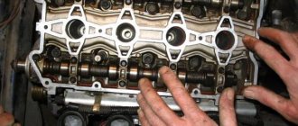
- First of all, molar liners are installed in the bed of the molar necks. Please note that the middle liner is different from the others. Before installing the bearings, the preservative lubricant is removed, after which a little motor oil is applied to the surface. After this, the bed covers are placed, after which the tightening is carried out. The tightening torque should be that recommended for the specific model of the power unit. For example, for engines on the VAZ 2108 model, this figure can be from 68 to 84 Nm.
- Next, the connecting rod bearings are installed. During assembly, it is necessary to accurately install the covers in place. The specified covers are marked, that is, their arbitrary installation is not allowed. The tightening torque of the connecting rod bearings is slightly less compared to the main bearings (the indicator ranges from 43 to 53 Nm). For Lada Priora, the main bearings are tightened with a torque of 68.31-84.38, and the connecting rod bearings have a tightening torque of 43.3-53.5.
Step-by-step method for replacing the rear wheel bearing on a VAZ 2109, 2110
- stop the car from the front;
- tear off the wheel bolts;
- tear off the central nut (7) of the hub, having first removed the cap (9);
- jack up the side and set the trestles;
- remove the wheel;
- fill the brake drum mounting area with WD-40 or other special liquids (you can use diesel fuel or brake fluid);
- unscrew the guide bolts (it is advisable to lightly tap with a hammer);
- we try to carefully remove the brake drum (if it doesn’t work, we screw the appropriate bolts into a special thread on the brake drum, apply tension and very lightly try to knock it out with a hammer. In most cases, the result will be positive. There are special drum pullers on sale, just in case , if all else fails);
- unscrew the central nut completely (of course, it is possible to unscrew it immediately, and even remove the hub along with the wheel and drum, but then there is a high probability of damage to the brake pads);
- we tighten the hub (if one of the inner races of the bearing remains on the axle, you need to use a puller or just a sharpened chisel to try to move it from its place);
- inspect the axle for signs of bearing rotation (if there are any, we replace it, it is advisable to replace the hub assembly);
- inspect the brake cylinder for leaks and pads for wear;
- remove the retaining ring from the hub using pliers and/or screwdrivers.
- Be sure to clean the edge from rust, moisten it with WD-40 or whatever you have on hand.
There are three options for pressing out the bearing:
- A special press (not everyone has one).
- A puller (not expensive, can be purchased, will be useful for the future).
- Using a heavy hammer (at least 2 kg) or a sledgehammer. AT first glance, the method may seem a little aggressive, but it is practiced by an overwhelming number of masters and service stations, and we will consider it.
- The hub must be firmly installed on a hard surface, and with several sharp blows through the mandrel, the bearing must be moved from its place. When this happens, you need to install the hub, for example, on a yew tree (so that there is a stop for the hub and free space for the bearing to exit)
- a few more blows and the bearing will come out (don’t rush to throw it away);
- We inspect the seating plane under the bearing, clean off the rust with sandpaper, lubricate it with regular engine oil (you can polish it off);
- the new bearing must be screwed with any suitable bolt through washers (washers must be selected according to the inner races, the bearing is double-row and during installation there is a high probability of its disassembly);
- install the hub on a hard surface.
– we place a twisted bearing on top, and lightly lubricate its mounting plane with oil (a new good bearing usually does not need to be lubricated inside, but if you have doubts and a little experience in assembling and disassembling, you can use Litol -24 lubricant)
– with an ordinary 500-gram hammer, very lightly, we try to align the bearing in the plane;
– take a suitable mandrel (for example, a pry bar), and try to press the bearing in with gentle blows.
-the basic rule is no strong blows, if it doesn’t work, it means it’s crooked
– after the bearing has passed halfway, you can no longer apply much force, since it can no longer warp.
-when we reach the cut of the hub, it is necessary to use the old clip as a mandrel (no strong impacts, the metal is high-carbon, and with a strong impact it can burst and cause very serious injury)
– we push it all the way and install the stopper (if there are problems with installing the stopper, then most likely you did not finish it all the way) the stopper should easily spring into the groove;
Birth pangs
The VAZ-21179 engine did not appear out of nowhere. The entire previous history of its emergence is a series of active design work and periods of oblivion. It all started in the early 2000s with plans to create a new model at VAZ, belonging to class “C” - the “Silhouette” project. A heavier car required a more powerful engine.
The existing 16-valve 1.6-liter engines were not suitable for this purpose. It should be said that in the line of VAZ engines there was a power unit with a volume of 1.8 liters. We are talking about unit 2130, which was installed on all-wheel drive vehicles: the five-door Niva and the Nadezhda minivan.
However, it was designed exclusively for “tractor” traction and had a power of only 85 horsepower. Therefore, they began to develop a new engine for the Silhouette project. Then management plans changed, and the developments were archived.
In 2008, they returned to the previous idea again, but they decided not to attempt a completely new unit, but to limit themselves to a deep modernization of the old 1.6-liter due to a lack of funding. One of the planned innovative solutions was the use of a variable valve timing system.
Since VAZ engineers had no experience in this area, it was decided to enter into a contract with the English concern Ricardo, which has the necessary competencies, to carry out calculation and research work. Also, at one time, thanks to cooperation with Porsche, a rather successful engine for the V8 was created, which became the prototype for all subsequent front-wheel drive models.
Work was stopped several times, then resumed again, as VAZ, like the entire Russian economy, was going through difficult times. And suddenly, completely unexpectedly, in March 2016, a new VAZ engine with the index 21179 was put into mass production.
Flywheel mounting diagram
For the convenience of the user, auto manufacturers shift the axis of one threaded hole for the flywheel bolts by several degrees, so it is physically impossible to install this part incorrectly. However, drivers usually take additional precautions by marking them with paint during dismantling.
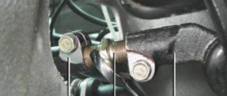
By analogy with flange connections, 6 bolts are used here, screwed into the crankshaft body, located at 60 degrees, except for one specially offset. For this formula of a threaded connection, tightening according to a special scheme is used, since there is no full-fledged “cross” here:
- two bolts opposite each other along the diameter axis;
- two bolts next to the previous ones in the same sequence;
- the remaining two bolts follow the same principle.
Attention: It is prohibited to use tubular “amplifiers” and extend keys. Instead, a torque wrench should be used.
Why does the bolts cut off?
When asked whether it is necessary to change the bolts for fixing the flywheel on the crankshaft, each manufacturer answers in advance, in the operating instructions - if possible, with each disassembly of this unit. A bolt can be cut for several reasons:
- the occurrence of backlash when unscrewing, an increase in the lever for shearing forces;
- incorrect choice of bolt strength class.
When retightening the thread, the working forces cannot cut the bolt, since the fasteners simply fall out due to the cut threads.
Fastener selection
To prevent the fastening element from breaking during engine operation, designers calculate the bolts based on loads. Known data are:
Disassembling the unit
Let's say you start making repairs on the left side of the car. The first thing you need to do is unlock the nut and unscrew it using a 30mm wrench. But you shouldn’t unscrew it all the way, it’s enough just to tear it off the thread. Then raise the left side of the car using a jack. Remove the bolts that secure the wheel to the hub. Then you need to unscrew the two bolts that secure the front wheel brake caliper. Without this, it is impossible to replace the VAZ-2110 wheel bearing.
Once you have freed the brake disc from the caliper, you can remove the latter. Just be careful not to damage the hose. After this, unscrew the guides that are on the disk. They attach it to the hub. Then you need to remove the brake disc. That's it, you've reached the hub itself. But it has two attachment points - to the rack and the lower arm. The upper mount to the rack must be marked so as not to disturb the camber of the front wheels. Then remove the two bolts that secure the ball joint to the lower control arm. Next, tear off the hub from the grenade slots.
Application
At first, only front-wheel drive Lada Xray crossovers were equipped with the VAZ-21179 engine, then they began to install it on the Lada Vesta sedan. The popularity of the internal combustion engine continues to grow along with its demand - we have already mentioned AvtoVAZ’s plans to equip the all-wheel drive Lada Niva with this engine. It is possible that the expected all-wheel drive version of the Lada XRay will receive this engine corresponding to the “crossover” class, which will be quite appropriate for Largus, Kalina and Granta.
As the developers of the VAZ-21179 say, in this engine they combined many of their technical ideas, but not all of them. So, the prospects are the brightest, the VAZ-21238 is on the way - the same VAZ-21179, but with two phase shifters, which will seriously change the characteristics of the engine, and for the better.
Adjustment
Checking its functionality and adjusting it is carried out as follows:
- Raise the front wheel using a jack;
- Remove the wheel;
- Using a chisel, remove the protective cap on the front hub bearing;
- Remove the brake pads;
- The indicator holder should be secured to the steering knuckle;
- Place the leg of this indicator against the hub, as close as possible to the adjusting nut;
- Rings of spanners are placed on the studs and the nuts are tightened. While holding them, the hub rotates and moves in the axial direction;
- Using the indicator, the movement or gap indicator is determined. If it is more than 0.15 millimeters, the gap must be adjusted;
- Reinstall the wheel without using the protective cap. Secure it with two bolts screwed in diametrically;
- Using a chisel, straighten the flange on the bearing nut and remove the nut with a 27mm (socket) wrench;
- Using a torque of 2.0 kg-cm, tighten the new adjusting nut;
- Loosen the nut, then tighten it again, but now with a torque of 0.7;
- Slowly release the adjusting nut 25 degrees and turn the wheel in a vertical plane. There should be a slight play;
- Check the gap. Its indicators should be in the range from 0.08 to 0.02 millimeters;
- In this position, lock the nut with the collar caulked in special grooves. They are located on the steering knuckle at the end of its axle;
- Remove old grease from the protective cap and apply new one. About 25 grams. Experts recommend using Litol 24, although there are worthy alternatives;
- Install the protective cap on the bearing;
- The wheel is installed in its rightful place.
Such diagnostics with repair elements will extend the life of your wheel bearing. If the adjustment does not allow the gap to return to the required parameters, the bearing should be completely replaced.
Removing the flywheel
Before unscrewing the flywheel from the crankshaft, you will need to provide access to this unit. To do this, the car is placed on a pit and jacked up to remove the front driver's wheel, or driven onto a lift. The sequence of actions is as follows:
- oil is drained from the gearbox;
- the starter and gearbox are dismantled, the clutch is removed;
- despite the asymmetrical arrangement of one bolt, a mark is made on the relative position of the crankshaft and flywheel;
- stuck bolts are treated with WD-40 aerosol, unscrewed halfway while holding the flywheel from turning with a screwdriver using the gearbox mounting bolt, which is screwed in specifically for this purpose;
- First, 5 bolts are completely unscrewed, then the last one is unscrewed, while the flywheel is held against falling by the user’s free hand.
The main problem is broken bolts, the threaded part of which remains flush in the crankshaft body, and cut threads inside the flywheel holes. The first problem is solved by drilling a blind hole in the body of the bolt fragment, into which a special tool is inserted - an extractor.
Design nuances
The 21179 engine bears little resemblance to the basic version 21127, as both the design and appearance have changed:
- phasing of intake valves within ±30 degrees;
- hollow camshafts with cams using powder metallurgy;
- vortex air supply into the combustion chamber;
- cylinder cooling system (jacket);
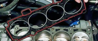
- improved configuration and cylinder head gasket volumes;
- ShPG Federal Mogul;
- Korean pump;
- inclined drilling of oil channels in the crankshaft journals;
- polymer cylinder head cover and solid aluminum pan;
- flywheel for clutch 215 mm, which is recommended by the manufacturer.
Motor gaskets
ShPG from Federal Mogul
Cylinder head bolt VAZ 2112 PAYEN turbo M10*1.25 (10 pieces)
- Engine Crankshaft
- Flywheel
- VAZ cylinder head
- Sports camshafts
- Sport timing valves
- Cylinder head components
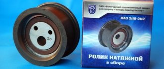
- Belts | Timing gears
- Gaskets | Oil seals
- Intake system
- Throttle valve
- Clubturbo pistons
- TDMK pistons
- Federal Mogul pistons
- Piston rings
- Connecting rods
- Engine mounts
- Inserts for VAZ engines
- ACL earbuds
- Oil catchers
- Oil crankcase
- Oil pump
- Miscellaneous
Cooling
- Adapters for installing an oil cooler | sensors
Cooling systems for VAZ 2101-2107 16v Cooling radiators Oil radiators Heater radiators Water pumps Fans Thermostats Expansion tanks Miscellaneous Silicone
- Straight pipes
Tubes with flange Tubes with 45 degree rotation Tubes with 90 degree rotation Tubes with 135 degree rotation Hoses Mishimoto Silicone Tubes Silicone Tubes for Cooling System Transmission
- Blocking
Main pair of vases Sports rows of gearboxes Gears 6th transmission of vases Drives of vases Clutch Short-stroke rocker Gearbox sport Rear axle gearbox of vases Spare parts of gearboxes of vases Brake system
- Vacuum booster
Brake master cylinderRear disc brakesBrake discsHand brakesBrake padsFittings for the brake systemFlange washers | transition kitsPedal unitBrake force regulatorCaliper | brake slave cylinderMiscellaneousSuspension
- Clubturbo suspension
Shock AbsorbersSprings Support BearingsTriangle ArmsStretchers | Amplifiers Safety frame Subframes Wheel spacers Steering Anti-roll bars Silent blocks | rubber bushings Silent blocks | polyurethane bushingsStuds | wheel nuts, swivel knuckles, joint heads | Sliding bearingsBall jointsMiscellaneousExhaust system
- Silencers for VAZ
Universal mufflersInsert catalystSpiderDownpipeResonators for VAZUniversal resonatorsBendsPipe | BendsVibration damper (corrugation)FlangesMiscellaneousElectronics
- Ignition system
Turbo timerControl units | WiringInstrumentsAir temperature sensorInnovateBoost controllerAbsolute pressure sensorMiscellaneousFuel system
- Filler necks
Fuel tanks Drain tanks Fuel pressure regulators Fuel rails (ramps) Brackets for fuel pumps Fuel pump Fillers for fuel tanks Fuel injector Fuel filters Hoses Miscellaneous Kits
- Moto kits Turbo
Engine displacement kitsExhaust system kitsE-GAS conversion kitStyling
- Adapters for installing sports steering wheels
Alternative opticsTow hooks | HingesDecorative license platesLocksMirrorsPodiums for instrumentsSeat beltsSteering wheelsGearbox lever capsSport seatsStorage and transportation systemsPedal coversHelmetsFiller capsMiscellaneous4×4Clothing and souvenirs
- Keychains
Vinyl for the car Club card, branded clothing Soft toys | PillowsWindshield stickersPostersMiscellaneousStickersSmartphone casesNailplatesKey lanyardsBody plastic
- Bumpers tuning for VAZ
Air intakesRadiator grillesGlass | Sports upholsteryFenders | Wheel arch extensionsDashboardsDoorsSpoilersLiningsHoodsTrunk lidsMudguardsPlastic body partsAileronsSkirtsMiscellaneousFittings
- Hoses | tubes
Fittings for rubber hosesFittings for Teflon hosesFittings for aluminum tubesCouplings| fittingsAN adapters - Metric threadAN adapters - Inch threadAN adapters - ANAdapters AN - ORBHose fasteningsWelded fittingsThrough the partition fittingsAN TeesPlugsMiscellaneousMiscellaneous
- Thermal insulation
Air filterOils and auto chemicalsToolsWiper bladesPneumohydraulic hood supports
- home
- Catalog
- Engine
- Miscellaneous
- Cylinder head bolt VAZ 2112 PAYEN turbo M10*1.25 (10 pieces)
Cylinder head bolt VAZ 2112 PAYEN turbo M10*1.25 (10 pieces)
PAYEN cylinder head bolts М10*1.25. For the cylinder head of a VAZ 2112. Bolts are used for a higher tightening torque. Installation only requires replacing your standard bolts. Recommended for use when installing turbocharging on a VAZ engine. A special tool is required for installation. Set of 10 pieces.
Specifications: