Contact group of the ignition switch gazelle next repair
GAZelle NEXT (2017).
Repair and replacement of the ignition switch If you need to replace the ignition switch, you must first disconnect it and then remove it. In this case, safety regulations must be strictly observed. Before you do anything, you need to prepare a screwdriver and an awl. You can consider how the lock and its parts are obtained and replaced. In such vehicles, the contact group is located at the bottom of the steering column. In case of changing the ignition switch, it is recommended to follow certain steps:
1. Dismantling the lock. First, the battery is disconnected by removing the negative terminal from it. The key is turned to the zero position, with the head of the key parallel to the floor. Next, unscrew the fasteners of the steering column casing. Then the screws securing the lock are unscrewed, while the key remains fixed. The clamp is tightened by inserting an awl into the hole in the bracket. When clamped, the key pulls towards itself. The wires are disconnected and the lock is removed.
2. Replacement of faulty elements. If it is necessary to replace the ignition switch element, it is necessary to separate this part in contact with the retaining ring, then install a new element at the same location.
3. Connecting contacts to the ignition system. When completing repairs or purchasing a new lock, you need to connect the contacts. This is not difficult to do, since there are markings on the terminal block of the lock that allow you to make the connection correctly.
4. Reinstalling the lock. In this case, the lock is recessed into the seat until it clicks. Then the fasteners are tightened and the casing is installed in its place.
After all these steps, you should check the proper operation of the ignition system.
Checking work
To check the correct connection of the repaired or new lock, you must again connect the negative terminal of the battery. Next, insert the ignition key into the lock. Then you should check whether the mechanisms are activated according to the position of the key in the lock.
Possible malfunctions of the ignition switch
The reasons for malfunctions in the ignition switch can be very diverse. Most often, breakdowns are associated with oxidation or melting of contacts, which is usually a consequence of sudden voltage changes. As a rule, this phenomenon is observed when the engine starts, when the temperature of the electrical wire material rises, as a result of which its insulating part burns out.
In this case, when you turn the ignition key in the lock, you will not get any reaction from the system, which automatically means the need to replace the lock contact group. There is no need to touch the lock itself.
Source
Replacing the ignition switch of a Gazelle car
Page 1 of 2
The ignition switch bracket is secured to the steering column with two bolts, the heads of which are sheared off at a certain tightening torque.
Replacing the contact part of the ignition switch
1. Disconnect the wire from the negative terminal of the battery.
To replace the contact part of the switch, remove the steering column covers (see the article - “Removing and disassembling the steering column”).
2. Using a slotted screwdriver, unscrew the two screws holding the steering column covers together.
3. Remove the top casing.
4. Move the steering column to its highest position.
We tilt the upper edge of the casing toward you until its lock comes out of the column slot.
5. Remove the casing by moving it upward.
6. Using a slotted screwdriver, unscrew the two screws securing the contact part of the ignition switch.
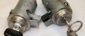
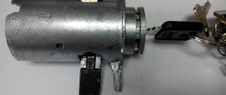
7. Remove the contact part from the lock body.
Disconnect the connection block of the switch.
R
is. 8
We connect the new switch to the connector, put it in place, aligning the groove in the hole with the protrusion on the lock, and fasten it with screws.
Contact group of the ignition switch gazelle next repair
GAZelle NEXT (2018). Ignition switch malfunctions
Main malfunctions of the ignition switch and their causes:
Ignition switch lock
You can’t call a blocking a malfunction, but many people are strangely afraid of it and really don’t know what to do. Steering column locking is present on every car as some kind of incomprehensible and unusually primitive protection against car theft that should create trouble for the thief.
What to do if the steering wheel is locked? You need to carefully scroll from side to side with one hand, and with the other hand, carefully and without sudden movements, try to turn the key; when you find the desired position, the key will turn.
Worn ignition switch contacts
For this reason, the ignition switch most often fails and the only solution to this problem is a contract lock or its repair.
Over time, gaps between parts in the ignition switch occur due to metal-on-metal friction, which naturally renders them unusable.
First, check the main key with the spare key, because if it is very worn, it is most likely the cause of the malfunction and try to start the engine with the spare key. If the key is in order, then all you have to do is make sure that the culprit is the ignition switch and buy a contract one.
Heavily worn parts make themselves known in advance by periodically jamming the lock. To avoid severe wear and tear, you should not hang heavy keychains and jewelry on the keys, yes, it’s beautiful and fashionable, but it breaks your lock at every bump, hole and turn.
Ignition switch frozen
This malfunction was included in the rating because With our frosts this happens often and often people pull the key in a frozen lock from side to side, eventually they break it and part of the key remains in the ignition, and then they have to buy a contract.
Solving this is quite simple, the main thing is not to rush, for this you will need: - a lighter or matches; -chemical defrost; -lungs full of air.
The first thing is to heat the key with a lighter or matches and insert it into the lock, carefully turning it several times.
The second method, a chemical defrost, will solve this problem very quickly, the main thing is not to overdo it with the liquid, just spray a little into the lock.
The third method is very effective, you take air into your lungs, lean against the lock and start blowing intensely into the ignition switch slot, don’t laugh because this technique is also suitable for locking doors, and everything is very simple, it’s winter outside and -20 degrees, and you exhale warm air that will melt the ice.
Dirty ignition switch
There are people who lubricate the ignition switch with engine oil in order to improve the operation of moving particles, but dust and other debris sticks to the oil and acts as sand, leading the parts to a deplorable state over time and, at best, the lock will simply jam and need cleaning.
First, disassemble and clean it with wd 40 or alcohol, you can do without disassembly by simply spraying liquid into the lock through a straw, if it helps, then rejoice.
The most important sign of a faulty lock contact group is the simultaneous failure of an entire group of electrical devices. This happens because within the group several electricity consumers are powered through each contact. For example, low and high beams, turn signals and reversing lights turn on only when the ignition is on. If the contact through which power is supplied to these consumers, say, burns out, then current will not be able to pass through it and the above-mentioned lighting devices will “fail.”
When several devices, seemingly unrelated to each other, stop working, the problem is almost always in the contact group of the ignition switch. Another “bottleneck” point is the fuse box, where several consumers can also be “suspended” to each socket. However, the same headlights are too powerful consumers, so even in the classics they are separated into separate fuses, and their failure together with the reversing lights clearly indicates a malfunction in the contact group of the ignition switch.
– A non-working starter, when neither the solenoid relay nor the control relay even clicks (they are simply not supplied with voltage through the contact group in the lock)
– Failure of electrical consumers, which, at first glance, are not connected in any way, but must work together in the same position of the ignition key.
– Restoring the functionality of devices when moving the key in the lock within one position (the contacts of the group are still in contact with undamaged areas and still pass current to consumers)
If there is at least one of the above symptoms, then with a high degree of probability we can talk about a malfunction of the ignition switch contact group. As a rule, the group cannot be repaired, so it is better to replace it.
Source
Ignition switch gas 3110 wiring diagram. Connecting the ignition switch gazelle
ignition switch gas 3110 wiring diagram
Mr. Stability Uploader 100+
ignition switch gas 3110 wiring diagram
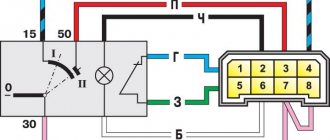
To check the ignition switch, sequentially set the key to the positions at which the circuits indicated in the table should be closed.
When the key is turned to position “III”, the anti-theft device should be activated. When turning the key from position “III” to position “0”, the anti-theft device should turn off. This can be checked by turning the steering wheel.
When restarting from position “I” to position “II”, the locking is activated. The key can only be turned to position “II” from position “0”.
If there are defects, replace the contact group or ignition switch.
Outdoor Lighting. Instrument lighting. High beam headlight alarm
Generator excitation winding. Ignition system. Windshield cleaner. Carburetor idle speed solenoid valve control unit. Direction indicators. Reversing light. Control devices
Low and high beam headlights. Fog light. Headlight cleaners. Rear window cleaner. Heated rear window. Washer. Heater fan. Engine cooling fan
Remove the six screws securing the lower steering column housing.
Remove the lower steering column cover.
. and ignition switch trim.
Remove the upper steering column cover.
Disconnect the ignition switch wiring harness from the wiring harness.
Disconnect the block with the ignition switch wires from the ignition relay.
Insert the key into the ignition switch and turn it to the “0” position to turn off the anti-theft device. Unscrew the four mounting bolts (two bolts are located on top of the column). Remove the bracket and ignition switch (see notes 1 and 2).
If the bolt heads are sheared off, the bolts must be drilled out or removed using a screwdriver and hammer.
Some cars are equipped with an ignition switch secured with two bolts. There is a slot at the top of the bracket that accepts the hook on the ignition switch housing.
Unscrew the screw securing the switch cover.
Remove the switch trim by pressing out the two plastic latches with a screwdriver.
Remove the contact group.
Assembling and installing the ignition switch is carried out in the reverse order.
The principle of operation of the Gazelle ignition system
First, let's look at the operating principle of the SZ Gazelle 402 engine. In this case, we are talking about any models of this car - both with a 406 engine and 5-seater Gazelles. The principle of operation of the SZ lies in the accumulation and further conversion of low-voltage voltage into high-voltage voltage using a coil after that. After conversion, the coil transmits and distributes high-voltage voltage to the spark plugs of the system. The spark plugs themselves are used to generate a spark, which, in turn, is necessary to ignite the air-fuel mixture in the cylinders.
The main stages of the work of the SZ:
- accumulation of low-voltage charge;
- converting it to high voltage;
- distribution of impulse over the corresponding candles in a certain order;
- creating a spark on the spark plug electrodes;
- ignition of a flammable mixture.
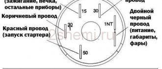
Pinout of Gazelle ignition switch contacts
Firing order
The connection diagram for the cylinders on the Gazelle, that is, the order of their activation, for the 406 engine is as follows:
- first the mixture ignites in the first cylinder;
- then the caviar is served on the third;
- after that - to the fourth cylinder;
- The second cylinder is the last to start working.
Basic elements of SZ
Briefly about the main components of SZ:
- an ignition module that includes several coils;
- switching device;
- distribution mechanism;
- candles;
- spark plug tips;
- elements connecting the spark plugs to the coil are high-voltage cables.
How does the ignition system work?
The system for models with a 402 engine functions similarly to those systems installed on cars with a 406 engine or in a five-seater vehicle. The main tasks performed by the installation are based on the accumulation and subsequent transformation of voltage from low voltage to high voltage. Coils are used for this.
The voltage converted from the coil is sent to the spark plugs screwed into the block. A spark is formed between the spark plug electrodes, which ignites the combustible mixture. The main stages for the Gazelle ignition system are:
- formation of sufficient charge with low voltage;
- raising the charge to high values;
- redistribution of impulse between candles in the sequence specified by the manufacturer;
- sparking at the tips of spark plug electrodes;
- timely ignition of the air-fuel mixture.
To start the rotation of the engine crankshaft, a starter built under the hood is used . Voltage begins to be supplied to it after turning the key to its extreme position.
Lock replacement and repair
If, when you try to turn on the key, nothing happens in the lock, that is, the engine does not start, the problem may lie in a poor connection of the contacts. You can try to repair such a lock, but if this does not help, then the device will have to be changed (the author of the video is Sergey Vishnyakov).
Replacing the contact group
This task is performed as follows:
- First you need to disconnect the battery, to do this, remove the negative terminal from it. Next, the protective lining of the steering column is dismantled. Using a flat head screwdriver, you will need to remove the two bolts that secure this shroud.
- Having done this, you can dismantle the upper part of the lining.
- Next, the steering column is moved to its highest position. You will need to slightly tilt the top of the cover towards you until the fastenings of this part of the casing come out of the slot.
- Then the lining is dismantled; it must be moved upward.
- Using a flat-head screwdriver, you will need to unscrew the two bolts that secure the contact part of the lock. Then the contact component is removed and replaced with a new one, further assembly is carried out in the reverse order.
Photo gallery “Changing the contact group”
Changing the lock
To completely change the lock, do the following:
- As in the previous case, you first need to remove the protective casing.
- It will not be possible to dismantle the clamp, since the standard nuts do not have edges, so it must be cut, for example, with a grinder. Be careful not to damage the steering column tube.
- Next, you will need to disable the steering column - this is done to make the further replacement procedure more convenient. First, the long screw connected to the steering wheel height adjuster is unscrewed. After this, the steering wheel itself should be lifted up, this will allow you to unscrew another bolt; for this, use a 12-mm wrench. When removing the screw, you will need to remember the position of the brace; it is located next to its head.
- The next step will be to remove the old ignition.
- Now take the new bracket and make slits in the sides where the lag screw heads will be located. The slots are a must because they will allow you to easily tighten the four lag screws. If the slots are missing, this will lead to the heads on the ratchet resting on the edges, so it will not be possible to securely fix the device.
- Next, the device is placed in the seat, four screws are tightened, they need to be tightened to the maximum. The two 12mm nuts that you unscrewed earlier do not need to be fully tightened, as this will result in you not being able to adjust the position of the steering wheel. Assemble the entire structure and test the operation of the installed lock.
How to replace the ignition switch of a Gazelle car
Page 1 of 2
The ignition switch bracket is secured to the steering column with two bolts, the heads of which are sheared off at a certain tightening torque.
Replacing the contact part of the ignition switch
1. Disconnect the wire from the negative terminal of the battery.
To replace the contact part of the switch, remove the steering column covers (see Removing and disassembling the steering column).
2. Using a slotted screwdriver, unscrew the two screws holding the steering column covers together.
3. Remove the top casing.
4. Move the steering column to its highest position.
We tilt the upper edge of the casing toward you until its lock comes out of the column slot.
5. Remove the casing by moving it upward.
6. Using a slotted screwdriver, unscrew the two screws securing the contact part of the ignition switch.
7. Remove the contact part from the lock body.
| Disconnect the connection block of the switch. | We connect the new switch to the connector, put it in place, aligning the groove in the hole with the protrusion on the lock, and fasten it with screws. |
Wiring diagram for Gazelle 402 engine: do-it-yourself replacement
Did you like the article? Follow our channel for new ideas of useful car tips. Subscribe to us in Yandex.Zen. Subscribe.
Having become an indispensable vehicle, the Gazelle with the 402 engine still requires attention over the years.
Electrical wiring is not listed among the parts subject to scheduled replacement, however, an electrical diagram is often required when carrying out repair work in the engine compartment.
Equipped with a ZMZ-402 carburetor engine, the car successfully exhausts its service life, and when the time comes for a major overhaul, many owners think not only about restoring, but also about reconfiguring its operation.
And since carburetor versions of power units have become a thing of the past, the question of the prospects for using a restored engine is urgent.
Electrical system of a Gazelle car
The transition to multi-valve injection engines is possible and even recommended by the automaker, but owners are not always satisfied with this approach, especially from the financial side.
Advice: Be that as it may, when removing the motor for overhaul, the owner has the opportunity to replace the old electrical wiring.
If the resource of the restored power unit inspires optimism, and you have a Gazelle wiring diagram at hand, the 402 engine may well last for hundreds of thousands of kilometers.
Replacing wiring on a Gazelle car
The reasons causing the need to replace the electrical wiring according to the diagram in Gazelle cars are not only due to the overhaul of the power unit, but also:
- Due to natural wear and tear of wires;
- Delamination of insulation due to natural aging;
- Mechanical damage (kinks, scuffs);
- Short circuits in one or another electrical circuit;
- Oxidation of contacts and connectors.
Additional replacement materials
In addition to purchasing new electrical wiring, those corresponding to the motor used must also be replaced:
- High voltage wires;
- Electronic switch (in later versions of motors of the ZMZ-402 series);
- Ignition coil;
- Battery charge level relay;
- Fuse block contact group;
- Egnition lock.
Places requiring installation work
Laying the wiring harness is not a difficult task, especially since the places for their attachment to the frame are provided initially (gutters, service holes, etc.).
However, according to complexity, replacement work is divided into areas of responsibility:
- Engine compartment;
- Vehicle interior;
- Rear part of the body.
The easiest part in terms of connection is the rear part of the car, where you only need to secure the harness and connect the rear lights and the fuel level sensor in the gas tank. The interior and engine compartment are more complex.
Complete lock replacement
To install a complete lock, you must first remove the contacts from the battery. Then you need to perform the following operations:
- We dismantle the casing;
- to remove the clamp, carefully use a grinder so as not to damage the main axis of the steering column;
- experts recommend turning off the steering column so that subsequent operations can be carried out conveniently, while the steering wheel is raised to its maximum height with preliminary loosening of the fixing bolt with a 12mm wrench;
- It is worth sketching or remembering the position of the curly bracket installed next to the head of the fixing bolt for subsequent comfortable assembly;
- dismantle the old ignition;
- we use a new bracket, make slots in the sides where the heads of the lag screws are supposed to be placed, otherwise the heads will rest against the edges, which will not allow them to be securely fixed;
- put the lock in the seat and screw in 4 screws with maximum force;
- A couple of 12 nuts, unscrewed in advance, should not be tightened to the maximum, so that there is still freedom to adjust the clamp.
Before installing the casing, we test the assembled unit for functionality. If problems arise, we bring the adjustments to working condition, and only then install the decor.
Replacing the ignition switch of a Gazelle car
Page 2 of 2
1. Remove the steering column cover.
2. Disconnect the ignition switch wiring harness block.
3. At the bottom of the ignition switch, unscrew the screw securing it to the bracket
4. On top of the switch, use a thin screwdriver to press the pin into the bracket body
5. Remove the switch from the bracket
6. Remove the two screws securing the contact group to the switch
7. Disconnect the contact group from the switch
If the new contact group does not have a wiring harness, unsolder the wires from the terminals,
having previously marked their position in any way.
It is necessary to mark it, because two wires are blue, and there are no pin markings on the contact block.
8.
Solder the wires as shown in the figure.
Install the parts in reverse order.
Removing the ignition switch assembly
To remove the ignition switch assembly, it is advisable to remove the steering column (see Removing and disassembling the steering column) and unscrew two special bolts.
1. If their heads are not broken off, then unscrew them with a “10” key.
2. Otherwise, remove the contact part of the ignition switch,
To avoid splitting it during operation, use a thin chisel to loosen the bolts.
3. Use pliers to unscrew the bolts.
4. Remove the lock.
For subsequent assembly we use new special bolts. To protect against theft, their hex heads can be broken off.
Installation of wiring on a Gazelle car
The wiring for Gazelle 402 is divided into the indicated zones.
Having laid out a new set of wires in a free place, its orientation will be immediately noticeable:
- The longest and thinnest tourniquet is intended for the back;
- The shorter one is for the interior;
- The largest number of wires and connectors is for the engine compartment.
The start of work on replacing the wiring is carried out from the cab:
- We fix the tourniquet in the cabin;
- We drag the second wiring harness under the hood and secure it;
- We drag the rear harness along the frame, connect the connectors, focusing on the colors of the wires;
In the engine compartment:
- We divide the harness into the right and left sides, focusing on the length and connectors;
- Connect the switch;
- We feed the wire to the generator;
- Connect the voltage regulator;
- Connect the ignition coil;
- We connect the terminals of the windshield wiper, turn relay;
Tip: the Gazelle 402 wiring is divided into colors that correspond to the colors shown in the diagram, as well as on the Gazelle Business wiring.
- We connect the connector to the fuse block;
- We feed the wire to the heater;
- We connect the light switch to the steering column;
- On the instrument panel, we power the central head light switch, the hazard warning button, and connect the devices.
Conclusions: using the factory wiring diagram of the Gazelle, regardless of the model - 406 or another, you can independently replace the old wires, adhering to the symbols and color designations.
Replacing the ignition switch gazelle 3302
Electrical diagram of a Gazelle car
Electrical diagram of Gazelle cars with UMZ-4216, ZMZ-40522 engines : 1- left side turn signal; 2 – left headlight; 3 – right headlight; 4 – right side turn signal; 5 – starter; 6 – fuse box (in the engine compartment); 7 – headlight relay; 8 – central lighting switch; 9, 10 – lampshades for cargo compartment lighting (for vans); 11 – canopy lighting for the front part of the cabin; 12 – windshield washer motor; 13 – courtesy lamp for the rear part of the cabin (for vehicles with two rows of seats); 14 – switch for the interior lighting of the rear part of the cabin (for vehicles with two rows of seats); 15 – platform lamp (GAZ-3302, -33021, -33027); 16 – buzzer switch (GAZ-3302, -33021, -33027); 17 – driver signal buzzer (GAZ-3302, -33021, -33027); 18 – sound signals; 19 – sound signal relay; 20 – ignition switch; 21 – starter relay; 22 – generator; 23 – battery; 24 – battery switch; 25 – button for remote battery switch; 26 – electric drive of the heater valve; 27 – electric pump for additional heater; 28 – heater electric fan resistor; 29 – heater fan electric motor; 30 – heating and ventilation control panel (1 – heater tap switch; 2 – heating and ventilation control panel backlight lamp; 3 – relay; 4 – main heater electric fan switch; 5 – auxiliary heater electric fan and electric pump switch); 31 – upper fuse box (in the cabin); 32 – lower fuse block (in the cabin); 33 – engine compartment lamp; 34 – hazard warning light switch; 35 – radio receiver; 36 – resistor of the additional heater electric motor; 37 – additional heater electric motor; 38 – interior lamp switch (right side); 39 – interior lamp switch (left side); 40 – lamp for lighting the steps (for buses); 41 – interior lamps (right side); 42 – interior lamp (left side); 43 – cigarette lighter; 44 – switch for checking the serviceability of signaling devices; 45 – sensor for emergency drop in brake fluid level; 46 – right steering column switch (switch for direction indicators and headlights); 47 – direction indicator relay; 48 – switch for electric headlight correctors; 49 – parking brake warning switch; 50 – parking brake warning relay; 51 – lighting control of the instrument cluster; 52 – connector (wire block) for connecting the ABS system; 53 – instrument cluster; 54 – brake signal switch; 55 – switch for the glove compartment lamp; 56 – lampshade lighting of the glove box; 57 – fuel module; 58 – center differential lock warning switch (for 4×4 vehicles); 59 – windshield wiper control relay; 60 – engine control system blocks; 61 – coolant temperature indicator sensor; 62 – coolant overheat indicator sensor; 63 – windshield wiper; 64 – oil pressure indicator sensor; 65 – emergency oil pressure indicator sensor; 66 – right steering column switch (horn and windshield wiper switch); 67 – speed sensor; 68 – reverse light switch; 69 – rear light (right); 70 – license plate lights; 71 – rear light (left)
Gazelle Ignition Switch
Ignition switch
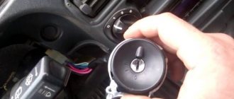
We are changing the ignition switch. I decided to change it because... It often happened that the key slipped, and already, the engine was running, but the starter was still spinning. You would start Plus, but the heater didn’t work, the low one didn’t light up (the key had to be moved here and there) I CHANGED IT IN 25, MINUTES ALREADY THE SECOND REPLACEMENT, the first was the first on the car, there I changed the hour. The best thing I bought a cheap one, I didn’t take Nizhny Novgorod for RUB 800. and it works fine (on an old, proven machine) Now I already know how to come up with something, modify it. I’ll explain in detail, because If people are faced with a replacement for the first time, then it will be incomprehensible to them anyway. If it’s problematic, read and also change it in 25 minutes))))) Disconnect the plug in advance.
1. Undress the steering wheel, remove the top and bottom plastic, the bottom one is problematic to remove, to do this, bend the steering wheel adjustment knob (first of course, unscrew the 2 screws of the ridge strip). Using a screwdriver:
2. It’s impossible to remove the clamp, the factory ones have no edge nuts, we cut them with a grinder mercilessly, the main thing is to stop in time, otherwise you’ll cut the main column steering pipe.
Removing the ignition switch assembly
To remove the ignition switch assembly, it is advisable to remove the steering column. How to remove, disassemble and adjust the steering column of a Gazelle car, unscrew two special bolts.
If their heads are not broken off, then unscrew them with a “10” key.
Otherwise, remove the contact part of the ignition switch so as not to split it during operation, loosen the bolts with a thin chisel
Use pliers to unscrew the bolts
For subsequent assembly we use new special bolts. To protect against theft, their hex heads can be broken off.
Source
Ignition and starter switch (ignition switch)
The switch consists of an anti-theft mechanical lock and an electrical switch. The switch key has four positions:
0 – ignition is turned off;
I – ignition is on;
II – the ignition and starter are turned on. Return to position I is automatic. The secondary activation of the starter is possible only after the key is turned to position 0.
III – the ignition is turned off and the anti-theft device is turned on when the key is removed.
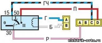
To check the serviceability of the ignition switch, it is necessary to assemble the electrical circuit shown in Fig. 9.27.
Electrical diagram for checking the ignition switch:
When turning the key to position I (ignition on), lamps A and B should light up, and when turning the key to position II (ignition and starter on), lamps A and B should light up. In positions 0 and III, lamps should not light up. The voltage drop between terminals 30/1 and 15/1 should not exceed 0.25 V at a current of 20 A. A faulty switch must be replaced.
1. You will be able to download the book immediately after payment.
2. The book will be downloaded in PDF format, and you can download it to any device.
1. All books are of ideal quality, since we work with publishers directly.
2. Electronic books are in no way inferior to paper books and are their complete analogue.
3. Our company has offices in Ukraine, Russia and Poland, you can always contact us at a specific address.
4. All payments on the site are maximally protected and are made using global payment systems.
The book is not intended for sale in your country.
You can place an order for the paper version of this book on the website autoinform96.com.
Payment for goods and downloading of the book in electronic form (PDF format) is made on the website.
To do this, you need to find the book you are interested in and click on the “Buy” button. The price of the book is indicated on the button.
For convenience, the price on the website for residents of Russia, Belarus and Kazakhstan is presented in rubles.
After clicking on the “BUY” button, a payment window will open where you can select a payment system with which you can pay for the selected book using any bank card (Visa, MasterCard, MIR, etc.)
When you click on the “Pay by bank card” button, the Portmone payment system will open, which is the easiest way to make a payment.
In addition, the website offers four payment systems for payment: