Hi all.
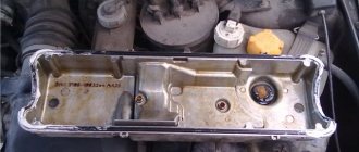
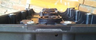
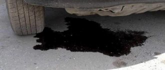
Last fall I noticed drops of oil in cylinder 4 and leaks around the entire perimeter of the valve cover.
I've been through the winter and it's time to fix the problem. I change everything together as usual. What we need:
1) Anaerobic sealant “Locktite” 20 ml - 150 rubles 2) Camshaft oil seal BRT (cat. number 21080-1005034-00) 2 pieces - 240 rubles per pair 3) Camshaft plugs 2 pieces (cat. number 21120-1003290- 00) - 100r pair 4) Crankcase ventilation pipes for engine 21126 (21126-1014240-00 (E-gas) - thin long, 21124-1014058-00 upper small, 21120-1014056-00) lower large - 3 pieces - 250r set 5) Filter “Knecht” KL23of - 150r 6) Carburetor cleaner - 150r 7) Intake manifold and throttle gaskets - 150r BRT set Oil dipstick seal (cat number 21120-1009078-00) - 30r 9) Torque wrench
I don’t see any point in describing the entire process of disassembling the valve cover. There are plenty of manuals, I’ll only focus on the moments that cause difficulties
Remove the decorative cover
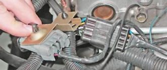
We remove all wires, ventilation hoses, and throttle. The receiver is secured with 2 bolts and 3 nuts. The nuts with the left bolt unscrew easily, you can crawl up. But there is a problem with the right bolt; the generator does not work.
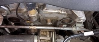
I have a car with air conditioning, the pipes are in the way. There are two bolts near the gene; we remove them (the bolts are visible in the photo). When you remove the intake manifold, you need to bend the tubes, don’t be afraid to bend them, there are rubber inserts there. We remove the generator belt, unscrew the top fastening and carefully move the gene towards the radiator with a pry bar.
Hatchbacks of the 2112 family were produced with different 16-valve engines - 21124 and 21120. Before removing the valve cover, on the VAZ-2112 you will need to disassemble the intake module mount, as well as remove all the brackets attached to the top of the cover. The high-voltage wires are also disconnected, and the ignition module is removed from the 21120 engine. Let's look at all the steps in more detail.
Removing camshafts and replacing valve lifters
We carry out work to replace camshafts and valve lifters.
Remove the plastic engine cover. Using a Phillips screwdriver, loosen the clamp securing the main crankcase ventilation hose... ...and remove the hose from the cylinder head cover fitting. We remove the intake pipe (see “Removing the intake pipe”) and cover the channels in the cylinder head with a rag to prevent objects from getting into the engine. We remove the ignition coils (see “Checking the condition and replacing spark plugs”). Using a Phillips screwdriver, loosen the clamp securing the crankcase ventilation idle circuit hose... ...and remove the hose from the cylinder head cover fitting.
Using a 10mm socket, unscrew the bolt securing the block bracket for the wiring harness of the engine management system... ...and remove the bracket with the blocks from the cylinder head cover. Squeezing the petals of the plastic holder of the engine management system wiring harness with pliers...
...remove the wire harness holder from the bracket secured to the cylinder head cover. Using a “8” socket, unscrew the 15 bolts securing the cylinder head cover.
Location of the cylinder head cover bolts The cover is installed on a sealant, so...
... use a screwdriver to pry the lid off the tide...
...and remove it. To check the serviceability of the hydraulic pusher...
... use a screwdriver to press on the hydraulic pusher (when checking, the camshaft cam corresponding to the hydraulic pusher should be facing the pusher with the “back of the head”, that is, do not put pressure on the pusher). In normal condition, the hydraulic tappet should move in the cylinder head socket with significant force, compressing the valve spring. If the hydraulic pusher itself is pressed with little force, then it must be replaced. We check other hydraulic pushers in the same way. Remove the camshaft gear pulleys (see “Replacing camshaft seals”). We disconnect the wire block from the sensor for the low (emergency) oil pressure warning light in the engine (see “Removing the low oil pressure warning light sensor”). Using the “8” head, unscrew the 20 bolts securing the camshaft bearing housing.
Location of the camshaft bearing housing bolts
Remove the camshaft bearing housing (A - housing alignment pins). In order to remove the camshafts from the supports in the cylinder head, you do not need to remove the rear timing belt cover, but only unscrew the three upper bolts securing the cover (see “Removing the coolant pump”). By pressing the rear timing belt cover...
...we take out the camshafts with oil seals.
To distinguish the shafts, a belt is made on the intake valve camshaft near its first neck.
Remove the two plugs from the cylinder head and the camshaft bearing housings. To remove the hydraulic pusher from the cylinder head socket, wipe the end of the pusher with a rag...
…and using a suction cup (you can use a suction cup to attach car accessories to the windshield)…
...take out the hydraulic pusher. When removing the hydraulic pusher, it is better not to use a magnet to avoid magnetization of the pusher parts and “sticking” of iron-containing wear products to them. Before assembly, we clean the mating surfaces of the cylinder head, bearing housing and cylinder head cover from the remains of old sealant and oil. Lubricate the bearing journals and cams of the camshafts with engine oil and place the shafts in the cylinder head supports. On the mating surface of the shaft bearing housing, mating with the cylinder head, we apply flange sealant of the Loctite type No. 574 with a bead about 2 mm thick.
Places for applying sealant to the bearing housing
We install the bearing housing along the centering pins and evenly tighten the fastening bolts crosswise, starting from the middle supports. We press in new camshaft oil seals (see “Replacing camshaft oil seals”). On the other side of the cylinder head, we press in the plugs using a mandrel. We carry out further assembly in reverse order. Before installing the cylinder head cover, apply Loctite No. 574 flange sealant to its surface mating with the bearing housing.
Places for applying sealant to the cylinder head cover
practical guide
1. Remove the air filter.
2. Remove the decorative trim of the engine.
3. Remove the ignition coils.
4. Remove the intake module.
5. Using an 8 mm socket wrench, unscrew the 15 bolts securing the cylinder head cover and remove the cover.
6. Remove the cover. Comment
If necessary, use a 10 mm wrench to unscrew the fastening bolt and remove the bracket for fastening the injector wiring harness pads and ignition coils from the cylinder head cover. Also, if necessary, loosen the clamps and disconnect the hoses from the cover.
Flushing
1. Using an 8 mm wrench, unscrew the six bolts securing the oil deflector.
2. Using a slotted screwdriver, press out the clamps of the oil filler neck.
3. Remove the oil deflector from the cylinder head cover.
4. Rocking from side to side, remove the oil filler neck.
5. Wash the removed parts in kerosene and wipe with a clean cloth.
6. Assemble the block head cover in the reverse order. Tighten the bolts to a torque of 1.9-4.6 Nm (0.2-0.5 kgcm)
Warning!
Don't forget to install lock washers under the bolt heads.
Installation
1. Clean the mating surfaces of the cover and bearing housing from sealant residues and degrease them with white spirit.
2. Apply a thin layer of heat-resistant sealant “Loctite-574” or similar to the mating plane of the bearing housing in accordance with the diagram shown in the photograph.
Warning!
When repairing an engine, do not use sealant with a high content of silicone (silicon compounds), the vapors of which can enter the cylinders through the crankcase ventilation system and then into the exhaust tract.
You should use a sealant that specifically states on the packaging that it is safe for the oxygen concentration sensor.
3. Reinstall the cover. We tighten the cover fastening bolts in the direction from the middle to the edges until the cover is pressed against the bearing housing. Finally, tighten the bolts to a torque of 1.9-4.6 Nm (0.2-0.5 kgcm).
4. Install the parts in reverse order.
Add a comment Cancel reply
You must be logged in to post a comment.
Lada Priora - replacing the cylinder head cover gasket
cylinder head cover gasket on a Lada Priora car is replaced with a new one if it is damaged, when oil begins to leak at the junction of the cover with the head, or it has become very compressed during use. To perform repair work, prepare a standard set of tools and perform the following sequence of actions:
- First you need to turn off the power to the car; to do this, disconnect the minus terminal from the battery.
- Now we disconnect the connector with wires from the ignition coil wire harness and the fuel injector supply wire harness.
- We squeeze the clamps of the harnesses with our fingers, which hold them motionless, and disconnect them, after which we move them to the side.
- Next, remove the front and rear mounts; to do this, unscrew one bolt each securing them to the cylinder head.
How to remove the valve cover on a Priora 1.6 16kl
I figuratively show how this is done, although this is the first time I’ve tried it myself - link to.
Eliminate oil leaks from valve covers! VAZ 21112
Eliminating oil leaks in a VAZ 2112 on a 1.6 liter engine. 16th grade with your own hands! PART 2.
- Disconnect the crankcase ventilation exhaust hose from the cylinder by loosening its clamp.
- Then, in the same way, loosen the clamp and remove the exhaust hose from the cylinder block pipe.
- Now we unscrew the screw securing the bracket that guides the dipstick of the oil level indicator in the engine crankcase and remove it together with the dipstick.
Removing the valve cover of Priora 16 valves
The work is shown on the 21124 engine. Features of removing the cylinder head cover from the 2112 cm engine are in the text.
To complete the work you will need a 10 mm wrench,
8 mm socket wrench
1. We prepare the car for work (see “Preparing the car for maintenance and repair”).
2. Remove the air filter (see “Air filter - removal and installation”).
3. Remove the decorative trim of the engine (see “Decorative trim of the engine - removal and installation”).
4. On engine 21124
remove the ignition coils (see “Ignition coils of engine 21124 (1.6i 16V) - check and replacement”), on engine 2112
remove the ignition module (see “Engine ignition module 2112 (1.5i 16V) - check and replacement”).
5. Remove the intake pipe on engine 21124
(see “Intake pipe of engine 21124 (1.6i 16V) - removal and installation, replacement of o-rings”), on engine 2112
remove the receiver (see “Engine receiver 2112 (1.5i 16V) - removal and installation”) and disconnect the crankcase ventilation hose from the cover pipe.
Repairing engine 21126 VAZ 2170 Priora after timing belt break
Today we brought one of the old clients to the Priora, as it turned out, the jammed pump broke the belt and, as a result, the valves were bent.
But progress at AvtoVAZ does not stand still, and if on the engines of the tenth family the valves were simply bent, then on the Priora 126s the connecting rods also lose alignment and, if they are not changed, there is a high probability that the engine will begin to eat oil and, accordingly, your money. Glory to the designers of AvtoVAZ!
But every cloud has a silver lining, there are sets of pistons for 126 engines with grooves that do not bend the valves. In this article we will describe the procedure for repairing the cylinder head after a broken timing belt, as well as replacing the piston. Removing and installing the timing belt is described in this article, so we will not dwell on it in detail.
Mistakes that novice mechanics make
Errors in installing the gasket are another reason for replacement. As mentioned above, during the replacement process it is necessary to thoroughly clean the contact planes. If this is not done, the seal will soon leak and will have to be replaced.
Novice mechanics often rush and forget about this point.
Another common mistake is neglecting the torque wrench. The fasteners are tightened sufficiently. In this case, the sealing element is pinched, squeezed out, and there can be no talk of any kind of sealing.
Also, due to improper tightening, the seal is pressed unevenly onto the planes.
What is a valve cover gasket?
In most cars, both domestic and foreign, this gasket is installed between the top engine cover, under which the camshafts are located, and the cylinder head. It is a thin rubber or rubber-cork product, the figured shape of which follows the shape of the power unit. The gasket is inserted into special grooves in the cover and tightly clamped with bolts to prevent oil from leaking through it.
Valve cover gaskets can be:
- Silicone.
- Rubber.
- Cork.
- Rubber-cork (a mixture of the two previous materials)
The material depends on the car model and manufacturer. The main requirement for it is resistance to contact with oil, elasticity, and retention of size at high and low temperatures.
Requirements
Lada Priora Sedan Snezhka Logbook Replacing the support bearing
When choosing a high-quality sealant intended for engine repair, valve cover connection and oil pan installation, you should pay attention to its performance characteristics and capabilities. It is in this category of sealing agents that one of the key factors is considered to be performance under conditions of high temperature loads
The greater the thermal load the composition can withstand, the better.
It is in this category of sealing agents that one of the key factors is considered to be performance under conditions of high temperature loads. The greater the thermal load the composition can withstand, the better.
There is also another important factor. It consists in resistance to the effects of various aggressive components. These include brake fluid, solvents, motor oil, gearbox lubricants, antifreeze, etc.
The third requirement is resistance to mechanical loads and vibrations that occur, which are integral companions of any internal combustion engine during its operation, even on the most ideal roads. If the composition does not have such properties, after a short period of time the active process of destruction of the frozen sealing layer will begin. We present to your attention the 1xSlots promo code for 100 free spins for registration. Here you will find more than 90 providers, live dealers, regular tournaments and a convenient status system for players. 1xSlots promotional code upon registration Gives a bonus on the first deposit in the form of free spins to new players.. Registration at the casino (BONUSES)! Each gaming club strives to take care of its client in the form of monetary rewards of various kinds. Users of 1xSlots casino experience the pleasant and friendly atmosphere of this gaming club.
The last but not least important requirement is ease of use. Here you need to use the appropriate type of packaging. The motorist should not have any problems applying the composition to the surface of the valve cover or the same internal combustion engine crankcase.
Let's start to disassemble
First, drain the oil and antifreeze. We remove the protective cover, the air filter with pipes, disconnect the ignition coil connectors, the throttle cable and the throttle assembly.
We remove the thermostat housing and simultaneously disconnect all the available connectors and pipes. We remove all the wiring that was in our way towards the battery.
We remove the generator. We unscrew the eight thirteen nuts holding the intake manifold and remove it. We unscrew all the bolts securing the valve cover, as well as the side engine support.
Unscrew the eight nuts and remove the exhaust manifold.
Remove the timing belt, camshaft pulleys and pump.
In three passes, so as not to deform the part, we first loosen and then unscrew twenty bolts of the camshaft bearing housing, the head is eight. Be sure to follow the sequence shown in the photo.
Remove the bearing housing. We remove the camshafts; there is a distinctive lip on the intake camshaft.
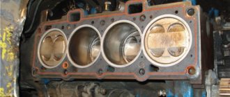
Also, in several passes, we first loosen and then unscrew the ten cylinder head mounting bolts. Be sure to follow the sequence shown in the photo.
Remove the cylinder head. All sixteen valves are replaced.
Removing the valve covers on engine 21120 (16v 1.5)
Briefly, the sequence looks like this: remove the filter box and the plastic trim, disconnect the wires and unscrew the ignition module. The key must be turned to position “0”.
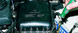
Removing the air filter box
To remove the filter, loosen clamps 1 and 2, and then disconnect connector 3. Pipes 1 and 2 are removed from the box. Use a 10mm wrench to unscrew the screw on the body, then remove the box from its mountings.
With a plastic cover, everything looks simple: either it is screwed on with bolts (key “10”), or held on with rubber bands. In the first case, the bolts are unscrewed, in the second, the cover is pulled up. The main thing is to unscrew the filler plug.
To disconnect high-voltage cables, you need to pull the caps out of the wells. The cables are also disconnected from the ignition module. It is pressed to the valve cover with three 10mm nuts.
Cylinder head repair
We mark all hydraulic compensators with numbers using an ordinary clerical touch and put them away. An ordinary magnet will help you pull them out. We dry out the valves and remove the oil seals (valve seals), the valves into scrap metal, the oil seals into the trash. We clean all channels. We take the head for grinding, just in case. After washing it again with kerosene after sanding and blowing it with air, we begin to assemble it.
We arrange the freshly purchased valves in the sequence in which they will stand in the cylinder head and begin to grind in one by one. Lubricate the valve stem with clean oil and apply lapping paste to the edge.
We insert the valve into place and put a valve grinding tool on the valve stem. The stores sell a device for manual lapping, but since this is the twenty-first century, we are mechanizing the process. We take the old valve and cut off the rod from it, select a rubber tube for it of such a diameter that it fits tightly. The rod is in a reversible drill, one end of the tube is on it, the other is on the valve being ground in. At low speeds we begin to grind the valve, constantly change the direction of rotation and periodically press it to the seat or weaken the force. On average, the valve takes about twenty seconds. We take it out and wipe it. The valve is considered ground in if a uniform gray strip of at least 1.5 mm wide appears on the chamfer.
The same stripe should appear on the valve seat.
Video of manually grinding valves
For a sixteen valve head, everything is the same, only there are twice as many valves. After lapping, all valves and seats are thoroughly wiped and washed with kerosene to remove any remaining lapping paste. We check for leaks. We tighten the old spark plugs and put all the valves in place. Pour kerosene and wait three minutes, if the kerosene does not run away all is well, otherwise we grind the valves on this cylinder.
We had to grind four valves again, after which the kerosene stopped flowing.
We stuff new valve seals.
We put the valves in place and dry them. Before doing this, lubricate the valve stems with clean oil. After lubricating it with clean oil, we put the hydraulic compensators in place and, covering them with a clean cloth, remove the head out of sight. We're done with the cylinder head.
Review of popular sealants
A review of valve cover sealants will help car owners decide on a specific brand, since many of these products are currently available in automotive stores and markets. And only reviews after actual use can give a comprehensive answer as to which sealant is better. Being extra careful in your selection will help protect you from purchasing counterfeit goods.
Black Heat Resistant DoneDeal
This is one of the highest quality sealants made in the USA. Designed to work in a temperature range from -70°C to +345°C. In addition to the valve cover, the tool can also be used to install the engine and transmission oil pan, intake manifold, water pump, thermostat housing, motor cover. It has low volatility, so it can be used in engines with oxygen sensors. The sealant composition is resistant to oils, water, antifreeze, lubricants, including motor and transmission oils.
The sealant withstands shock, vibration and extreme temperatures. At high temperatures it does not lose its performance properties and does not crumble. The product can be applied to existing gaskets to extend their life and improve their heat resistance. Does not cause corrosion of metal surfaces of engine parts.
Product code DD6712. Package volume: 85 grams. Its price since winter 2017/2018 is 300 rubles.
ABRO 11-AB
A good sealant, popular for its low price and decent characteristics. It can also be used when installing various other seals on a vehicle. Therefore, this tool will definitely come in handy in the future when repairing your car.
On the left is the original ABRO packaging, and on the right is a fake
Features and Specifications:
- maximum use temperature - + 343 ° C;
- has a chemically stable composition that is not affected by oils, fuel, antifreeze, water and other process fluids used in the car;
- perfectly withstands mechanical loads (significant loads, vibrations, displacements);
- comes in a tube with a special “spout” that allows you to apply a thin layer of sealant to the surface.
Note! Currently, a large number of counterfeit products are sold in automobile markets and stores. In particular, the production of ABRO RED in China is essentially an analogue of sealant with much worse performance characteristics. Using the images below, you can distinguish the original packaging from the fake one. It is sold in a tube weighing 85 grams, the price of which since the winter of 2017/2018 is about 200 rubles.
Victor Reinz
In this case we are talking about REINZOPLAST sealant, which, unlike REINZOSIL silicone, is not gray, but blue. It has similar performance characteristics: stable chemical composition (does not react with oils, fuel, water, aggressive chemicals). The operating temperature range of the sealant is from -50 ° C to + 250 ° C. A short-term increase in temperature to + 300 ° C is allowed while maintaining performance characteristics. An additional advantage is that the dried composition can be easily removed from the surface - it leaves virtually no traces on it. This is a universal gasket sealant. The catalog number for ordering a 100 g tube is 702457120. The average price is about 300 rubles.
The advantage of Victor Reinz sealants is that they dry quickly. You will find exact instructions for use on the packaging, but in most cases the algorithm for use will be as follows: apply sealant to the work surface, wait 10.15 minutes, install the gasket. And, unlike other sealants, your car's engine can be started within 30 minutes (though it's best to wait even longer, if applicable).
Dirko
This brand of sealant is manufactured by Elring. Popular products of this brand are: Dirko HT and Dirko-S Profi Press HT. They have similar characteristics, both among themselves and in relation to the sealants described above. In particular, they are resistant to the listed process fluids (water, oils, fuel, antifreeze, etc.), They have proven themselves under conditions of high mechanical loads and vibrations. The operating temperature range of Dirko HT (a tube weighing 70 grams has code 705.705 and the price is 300 rubles from the winter of 2017/2018) from -50 ° to + 250 ° C. A short-term increase in temperature to + 300 ° C is allowed while maintaining operability. The operating temperature range of Dirko-S Profi Press HT is from -50 ° to + 220 ° C (a tube weighing 200 grams has a code of 129,400 and a price of 1,000 rubles for the same period). A short-term increase in temperature to + 300 ° C is also allowed.
Types of sealants TM Dirko
There is also Dirko Spezial-Silikon (70 gram tube code 030.790), specially designed for sealing oil pan and crankcase covers. It is especially recommended to use on surfaces subject to deformation during operation. Operating temperature range -50°C to +180°C.
As for styling, after applying the product to the surface, you need to wait 5-10 minutes. Please note that the time should not exceed 10 minutes, as the protective film is formed within the specified period of time. The sealant can then be applied to the gasket.
Anaerobic sealant Permatex Anaerobic Gasket Maker
Permatex Anaerobic Sealant is a thick compound that quickly bonds to the aluminum surface when it cures. The result is a strong yet flexible connection that is resistant to vibration, mechanical stress, aggressive process fluids and extreme temperatures. Sold in a 50 ml tube, starting from winter 2017/2018 the cost is about 700 rubles.
Other popular brands
Currently, the market for sealants, including high-temperature sealants, is very saturated. It is necessary to understand that the range of different brands in the corners of our country is different. This is mainly due to logistics, as well as the presence of our own production facilities in a particular region. However, the following sealants are also popular among domestic motorists:
- CYCLO HI-Temp C-952 (tube weight - 85 grams). Red silicone car sealant. Rarely found on sale, but considered one of the best of its kind.
- Smoked. A series of sealants from the aforementioned Elring company is also very popular. The first brand is Curil K2. Temperature range from -40 ° to + 200 ° C. The second is Kuril T. Temperature range - from -40 ° C to + 250 ° C. Both sealants have a wide range of applications, including use in crankcases. Both are sold in a 75 gram dispenser tube. Curil K2 has code 532215 and costs 350 rubles. The cost of Curil T from winter 2017/2018 is about 400 rubles.
- MANNOL 9914 RED seal manufacturer. It is a one-component silicone sealant with a working temperature range from -50 ° C to + 300 ° C. Very resistant to high temperatures, as well as to fuels, oils and various process fluids. The sealant must be applied to a degreased surface! Complete drying time is 24 hours. The price of a tube weighing 85 grams is 170 rubles.
All sealants listed in this section are resistant to fuels, oils, hot and cold water, weak solutions of acids and alkalis. Therefore, it can be used as a valve cover sealant.
Let's move on to the cylinder block
We remove the pallet. Rotating the crankshaft as it is convenient for us, unscrew two bolts on each connecting rod cap. We use a TORX E10 head for this.
We take out the pistons along with the connecting rods. To do this, use the wooden handle of a hammer to press the connecting rod from below and lightly tap it to knock it up. We remove the old liners and buy new ones of the same size according to the markings on them. Here is another stone in AvtoVAZ’s garden, the owner has never climbed into the car from the interior or into the engine, but three pistons were of group “B” and one was “C”. It turns out that at the factory they re-sharpened one cylinder a little and simply put an enlarged piston there, no words. There are no options, we take group “C”, don’t sharpen the engine because of this. We will not touch the main liners either.
We buy a new piston group that does not bend the valves, connecting rods and connecting rod bearings.
Eliminating longitudinal play of the crankshaft
It was noticed on this motor. To eliminate it, replace the thrust half-rings. Standard and repair sizes are available. We take the first repair size, if they are too tight we sand them down a little. We unscrew the middle main bearing and gently push it with a screwdriver and move the half rings. The mark on it is in the form of three serifs, shown below.
Engine assembly
We wipe the crankshaft journals, cylinder bores and connecting rod bearing seats with a clean rag; by the way, they can also be degreased. We put new liners into the connecting rod and the cover, so that the antennae of the liners fit into the grooves.
Lubricate the bearings, crankshaft journals and cylinders with clean oil. We unfold the piston rings with locks as shown in the figure, the angle between them should be 120 degrees.
We put a mandrel on the piston to compress the rings, having previously lubricated it inside with clean oil. Not forgetting about the direction, the arrow on the piston should be directed towards the front of the engine, we place it in its cylinder.
We turn the crankshaft so that the connecting rod journal is at the very bottom. Gently tapping the wooden handle of a hammer pushes the piston into the cylinder. We remove the mandrel and push the piston down until the connecting rod sits on the crankshaft. We put the connecting rod bearing cap on the bottom, remembering the marks. Tighten the connecting rod cover mounting bolts to a torque of 5 kgf*m. We also repeat with all the other cylinders.
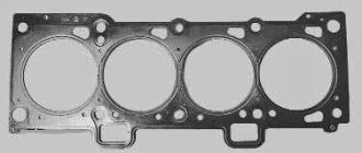
We put back everything that we removed from below. We blow through the top and clean the holes for the cylinder head mounting bolts. We install a new cylinder head gasket and the head itself. Lubricate the bolts with a thin layer of oil, most importantly without fanaticism. We tighten the bolts in several passes in the reverse order of unscrewing, see photo at the beginning of the article. The tightening sequence is as follows:
- first tighten everything with a torque of 2 kgf*m
- then we tighten everything to a torque of 7 – 8 kgf*m
- turn it 90 degrees
- turn it 90 degrees again
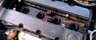
We install hydraulic compensators, camshafts and camshaft bearing caps. Lubricate all rubbing surfaces with clean oil. Before installing the camshaft bearing caps, lubricate the perimeter and rims around the spark plug wells with a thin layer of sealant. We tighten the bearing cover bolts in the reverse order of unwinding, with a torque of 2 kgf*m, see photo at the beginning. Well, then we install all the parts in the reverse order of removal. We fill in all the fluids and start it, it may not start right away, this is normal. When you first start it will smoke well until the oil on the cylinders burns, make sure the oil pressure light goes out. Let it run for a minute and turn it off, and suddenly see where something is leaking. We start it several more times, constantly increasing the operating interval, bring it to operating temperature, constantly checking the oil and antifreeze, and also pay attention to the fact that no extraneous noise appears. Let it rest for an hour and then idle again for about an hour, constantly monitoring the temperature. Well, then the break-in, if you sharpened it, if not, then you can drive only the first thousand kilometers, try not to raise the speed above 3000, and not tow it.