By following these simple rules, you can guarantee the best tightening and a reliable tight connection.
Place the cylinder head on the block, first making sure that the crankshafts and camshafts are set to the top dead center (TDC) position.
Proper twisting
The tightening process itself takes place in 4 circles:
- 1st circle - moment 20 N m (2 kgf/m);
2nd circle - moment 69.4–85.7 N·m (7.1–8.7 kgf·m);
As you can see, everything is simple. If you have any questions, watch the video. In terms of time, this work does not take more than twenty minutes, but it allows you to save a decent amount, which they will charge you at the service station.
In what cases is it necessary to tighten the block?
During the operation of any car, including the VAZ 2170 Priora, the engine head is exposed to long-term cyclic effects of gases located in the engine cylinders. On older power units, the tightening of the cylinder head screws could weaken under such loads and periodically needed to be brought to a normal level. Today, all VAZ Priora engines use bolts made of special steel, which are tightened once for their entire service life.
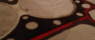
If a coolant and oil leak occurs, there is no point in further tightening and tightening these bolts, since this will not improve the tightness of the joint. The only correct way to combat a leak is to remove the head, check the evenness of the mating surfaces and replace the gasket. After performing any repair work related to removing the head from the engine, it must be tightened in compliance with all necessary conditions.
The video from the author Alex ZW shows the process of installing the cylinder head on an 8-valve engine.
General assembly information
Warnings before assembly
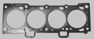
- When reassembling the engine, use only a new cylinder head gasket. It is not allowed to use a removed (even carefully) gasket.
- Also, do not forget that before installing it, you must thoroughly degrease the surfaces mating to it. The gasket itself must be clean and dry. Do not allow oil to come into contact with these surfaces.
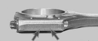
- Before assembly, check the cylinder block bolts; they should not be stretched, i.e. their length should not exceed 95mm. If so, replace them with new ones. The use of such extended bolts is not permitted!
- Before assembling the engine, lubricate the threads and bolt heads. Regular motor oil is suitable for lubrication. It is necessary to lubricate the bolts 30 minutes before using them so that excess oil has time to drain.
- When installing the timing belt, do not allow sharp bends (with a radius of less than 20 mm) to avoid damage to its cord.
The procedure for tightening the cylinder head bolts and the diagram for applying sealant to the camshaft bearing housing
Camshaft drive diagram 2112
1 – crankshaft toothed pulley; 2 – toothed belt; 3 – coolant pump pulley; 4 – tension roller; 5 – exhaust camshaft pulley; 6 – rear protective cover of the toothed belt; 7 – intake camshaft pulley; 8 – ring for phase sensor; 9 – support roller; A – TDC mark on the crankshaft toothed pulley; B – installation mark on the oil pump cover; C and F – installation marks on the rear protective cover of the toothed belt; D – installation mark on the exhaust camshaft pulley; E – installation mark on the intake camshaft pulley.
Scheme for applying sealant to the upper surface of the cylinder head
First of all, place a clean cylinder block on the stand and screw the studs into it (if some are missing). Remove the main bearing caps and press the missing piston cooling nozzles into the cylinder block using mandrel 67.7853.9621.
Install the crankshaft and connecting rod-piston group into the cylinder block, attach the flywheel to the crankshaft, install the oil pump and its oil receiver, the oil sump with a gasket and the oil filter, proceeding as described in the 2110 engine section. Then assemble the engine in the following order.
Insert two centering sleeves into the cylinder block and install the cylinder head gasket over them.
Rotate the crankshaft so that the pistons are in the middle of the cylinders.
Install the block head along the centering bushings. Tighten the cylinder head bolts in a certain sequence (Fig. Order of tightening the cylinder head bolts and diagram of applying sealant to the camshaft bearing housing) and in three steps:
– tighten the bolts to a torque of 20 Nm (2 kgfm);
– tighten the bolts 90°;
– tighten all bolts again by 90°.
Insert the coolant pump with the gasket into the cylinder block socket and secure it with bolts. Install and secure the rear timing belt cover.
Insert the keys into the slots on the front ends of the crankshaft and camshafts and install the timing pulleys. Having blocked the camshaft pulleys from turning, secure them with bolts and washers.
Using tool 67.7811.9509, turn the camshafts until the marks on the pulleys align with the installation marks on the rear protective cover of the toothed belt (Fig. Camshaft drive diagram).
Turn the crankshaft towards a smaller rotation angle until the timing mark on the pulley aligns with the mark on the oil pump cover. You can turn the crankshaft using a wrench using a bolt temporarily screwed into the front end of the crankshaft.
Install the tension roller and secure it in the position corresponding to the minimum belt tension. Install and secure the support roller.
Place the timing belt on the camshaft pulleys and, while tensioning both branches of the belt, place the left branch behind the tension roller and put it on the coolant pump pulley, and place the right branch behind the support roller. Place the belt on the crankshaft pulley and lightly tension the belt with the tension roller by turning the roller counterclockwise. When installing the belt, avoid sharp bends.
Turn the crankshaft two turns in the direction of rotation and check that the alignment marks match (see Fig. Camshaft drive diagram). If the marks do not match, then loosen the belt tension, remove it from the camshaft pulleys, turn the pulleys to the required angles, put on the belt, slightly tension it with the tension roller, turn the crankshaft two turns again and check that the alignment marks match.
If the marks match, adjust the belt tension as described below.
Install the phase sensor by attaching it to the cylinder head with two bolts. Install and secure the front timing belt guard.
Apply Loctite No. 574 type sealant to the upper surface of the camshaft bearing housing with a 2 mm diameter bead, as shown in Fig. Scheme of applying sealant to the upper surface of the cylinder head. Install the cover assembly with the separator, separator oil deflector and discharge pipe onto the block head and secure the cover with bolts.
Carefully insert the spark plugs into the head sockets and tighten them with the wrench 67.7812.9553.
Attach the cooling jacket outlet pipe with a gasket to the block head and secure it with two nuts. Install the gasket and attach the coolant pump inlet pipe flange to the cylinder block. Place the hoses leading to the thermostat onto the pipe and supply pipe, install the thermostat and secure the hoses with clamps.
Place a gasket on the cylinder head studs, install the exhaust manifold with a protective screen and secure them with nuts together with the coolant pump inlet pipe bracket.
Nuances of work
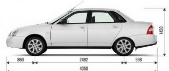
At different times, Lada Priora cars were equipped with engines with a displacement of 1.6 and 1.8 liters and a different number of valves in the heads - V8 (or 8V) and V16 (or 16V). The type of unit head determines the size of the bolts, the order of their installation and the tightening torque of the cylinder head on the Priora.
If the car has an 8-valve engine, then it can use head mounting bolts of different sizes:
- on old motors 21114, M12*1.25 hex head screws are used;
- on more modern 21116, which went into production approximately in mid-2011, M10*1.25 elements with an asterisk head are installed.
When installing a removed head, it is necessary to use new screws, since the old ones will be stretched and have internal damage.
Also, the engines use gaskets of different designs - combined on the old unit and all-iron on the new one. The procedure for tightening bolts for engines with metal and combined gaskets is absolutely identical.
The main nuances when performing work are checking the length of the fasteners, observing the sequence of tightening the screws and monitoring the tightening force. Violation of these conditions leads to damage to parts and the need for additional repair work. The procedure itself is not complicated and can be done independently in any convenient place - in a garage or in an open parking lot, with the exception of the case of installing the head on the engine, which is preferably installed indoors.
It is important to remember that tightening the bolts “by eye” without a torque wrench is unacceptable, since a uniform fit of the mating surfaces of the head and block will not be ensured.
Tools and materials
Before starting the tightening procedure, you should prepare everything necessary to perform:
- wrench with built-in dynamometer up to 100 H⋅m;
- a set of sockets and regular keys;
- Togh E14 key;
- calipers for measuring the remaining length of bolts;
- plate with a marked scale up to 180 degrees;
- new bolts.
A torque wrench is an important tool for DIY repairs.
Step-by-step instruction
Sequence of operation on an 8 valve engine:
- Wipe the cylinder head surfaces and dry the bolt holes in the engine block.
- Install the gasket on the block and align it along the guides.
- Mount the head on top and insert 10 M10 or M12 mounting bolts. If the owner decides to save money and keep the old screws, then they should have a length of no more than 135.5 mm.
- Tighten the elements according to the diagram. The tightening force should not exceed 20 N⋅m.
- Then you need to re-tighten the bolts. The second tightening force should be in the range from 70 to 85 N⋅m.
- Next, you need to tighten the screws by 90 degrees in the same sequence. The rotation angle can be controlled using a special device, which is a plate with an attached scale from 0 to 180 degrees.
- In accordance with the regulations, you need to tighten the bolts again by 90 degrees.
- The attachment of the 8 valve head to the block is complete.
- After assembling the motor, you need to check the quality of operation by starting and warming up the engine. A securely tightened joint between the head and the block should not allow working fluids to leak from the crankcase of the power unit.
Cylinder head repair
We mark all hydraulic compensators with numbers using an ordinary clerical touch and put them away. An ordinary magnet will help you pull them out. We dry out the valves and remove the oil seals (valve seals), the valves into scrap metal, the oil seals into the trash. We clean all channels. We take the head for grinding, just in case. After washing it again with kerosene after sanding and blowing it with air, we begin to assemble it.
We arrange the freshly purchased valves in the sequence in which they will stand in the cylinder head and begin to grind in one by one. Lubricate the valve stem with clean oil and apply lapping paste to the edge.
We insert the valve into place and put a valve grinding tool on the valve stem. The stores sell a device for manual lapping, but since this is the twenty-first century, we are mechanizing the process. We take the old valve and cut off the rod from it, select a rubber tube for it of such a diameter that it fits tightly. The rod is in a reversible drill, one end of the tube is on it, the other is on the valve being ground in. At low speeds we begin to grind the valve, constantly change the direction of rotation and periodically press it to the seat or weaken the force. On average, the valve takes about twenty seconds. We take it out and wipe it. The valve is considered ground in if a uniform gray strip of at least 1.5 mm wide appears on the chamfer.
The same stripe should appear on the valve seat.
Video of manually grinding valves
For a sixteen valve head, everything is the same, only there are twice as many valves.
After lapping, all valves and seats are thoroughly wiped and washed with kerosene to remove any remaining lapping paste. We check for leaks. We tighten the old spark plugs and put all the valves in place. Pour kerosene and wait three minutes, if the kerosene does not run away all is well, otherwise we grind the valves on this cylinder.
We had to grind four valves again, after which the kerosene stopped flowing.
We stuff new valve seals.
We put the valves in place and dry them. Before doing this, lubricate the valve stems with clean oil. After lubricating it with clean oil, we put the hydraulic compensators in place and, covering them with a clean cloth, remove the head out of sight. We're done with the cylinder head.
Video “Installing and tightening the cylinder head on a Priora”
The assembly of the upper part of a 16 valve engine is presented in a video from the Expert R channel.
I encountered the following problem: I replaced the piston with a plugless automatic transmission. The diesel is gone. But on a hot engine, a knock appeared, which directly depends on warming up. The feeling is that the block is moving away and the piston-cylinder gap is coming out (during installation I made 3 hundred parts). So the essence of the issue is that there are two tightening methods that I came across in the literature, 1st - a torque of 20 N m (2 kgf m); 2nd - torque 69.4–85.7 N m (7.1–8.7 kgf m); 3rd - tighten the bolts 90°; 4th - finally tighten the bolts 90°. or Using a torque wrench, tighten the head mounting bolts in three steps - first with a torque of 20 N m (2 kgf m), then turn the bolts by 90° and then turn the bolts again by 90°. I pulled the first one myself. Is the question correct? If you have links to sources, please share.
Torque wrench and its types
It is needed to tighten the cylinder head bolts. In 2022, devices are divided into three main types.
Snap key
A fairly popular type of device, widely used due to its moderate cost and ease of operation.
The principle of operation is based on setting the required torque on the main and auxiliary scales. When the set force is reached, the ratchet and key are activated and slip with a characteristic sound.
Arrow key
The very first and simplest variety, preserved from USSR times in many workshops. The operating principle is based on the resistance of the torsion bar when the torque increases.
The main disadvantage is the low accuracy of the device - over time, the torsion bar wears out and the key begins to lie in a larger direction.
Digital key
Digital devices are characterized by increased measurement accuracy, which allows them to be used on advanced internal combustion engines that require careful calibration.
Such keys are still rare in 2022 and are found mainly in workshops, due to their high cost.
Other devices
In the absence of a special tool, you can use improvised materials such as a long lever and a regular cantor. The point is to calculate the standard formula.
For example, to obtain a tightening torque of 10 Nm, you should use a 1 meter long lever and apply a force of 1 kg to its end.
Photo gallery
The photo below shows the procedure for loosening the bolts and tightening them, which must be taken into account when repairing the cylinder head on a VAZ 2170 Priora.
Scheme for loosening bolts on an engine with 8 valves
Scheme for loosening bolts on an engine with 16 valves
16 valve head tightening diagram
8 valve head tightening diagram
Let's start to disassemble
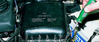
First drain the oil and antifreeze. We remove the protective cover, the air filter with hoses, and disconnect the connectors of the ignition coils, throttle cable and throttle assembly.
We remove the thermostat housing and at the same time disconnect all the connectors and hoses connecting them. We remove all the cables that were in our way towards the battery.
We remove the generator. We unscrew eight of the thirteen nuts holding the intake manifold and remove it. We unscrew all the bolts securing the valve cover, as well as the side engine support.
Unscrew the eight nuts and remove the exhaust manifold.
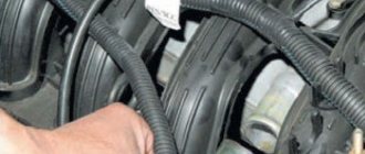
Remove the timing belt, camshaft pulleys and pump.
In three steps, so as not to deform the part, we first loosen and then unscrew twenty bolts of the camshaft bearing housing, head eight. Be sure to follow the sequence shown in the photo.
Remove the bearing housing. After removing the camshafts, there is a noticeable lip left on the intake camshaft.
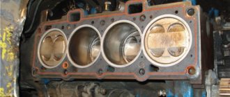
Also, in several steps, we first loosen and then unscrew the ten head bolts. Be sure to follow the sequence shown in the photo.
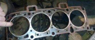
Remove the cylinder head. All sixteen valves have been replaced.