Replacing the cylinder head gasket for a VAZ 2170 Priora
- Repair manuals
- Repair manual for VAZ 2170 (Priora) 2004+.
- Replacing the cylinder head gasket
If you detect a leak of engine oil or coolant at the junction of the head and the cylinder block, remove the head and replace its gasket.
A leak can also occur due to warping of the block head due to overheating. You will need: a torque wrench, “13”, “17”, “19” keys, “10”, “13”, “17” socket heads, “10” hex key, screwdriver.
| Warning The head gasket is a one-time use unit, so each time the head is removed, the head gasket must be replaced. |
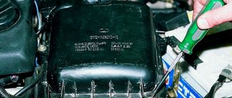
1. Remove the decorative engine cover (see “Removing and installing the decorative engine cover” ).
2. Set the piston of the 1st cylinder to the TDC position of the compression stroke (see “Installing the piston of the 1st cylinder to the TDC position of the compression stroke” ).
3. Reduce the pressure in the power system if the work is performed immediately after a trip (see “Reducing fuel pressure in the engine power system” ).
4. Disconnect the wire from the negative terminal of the battery.
5. Drain the coolant (see “Replacing the coolant” ).
6. Remove the air filter (see “Removing and installing the air filter” ).
7. Disconnect the heating hoses, the small branch of the crankcase ventilation system, the canister purge, the air supply hose, the wiring harness blocks of the throttle position sensor and the idle speed regulator from the throttle assembly (see “Removing and installing the throttle assembly” ).
8. Remove the throttle assembly (see “Removing and installing the throttle assembly” ).
9. Disconnect the wiring harness connectors from the ignition coils. Remove the ignition coils and remove the spark plugs (see “Replacing and servicing spark plugs” ).
| 10. Disconnect the wiring harness block from the emergency oil pressure drop sensor... | 11. ...from the coolant temperature sensor of the engine management system... |
| 12. ...and phase sensor. | 13. Loosen the clamps and disconnect the five cooling system hoses from the thermostat pipes. |
| 14. Disconnect the wiring harness connector from the coolant temperature gauge sensor. | 15. Using a 13mm wrench, unscrew the nut securing the tip of the “mass” wire... |
| 16. ...and remove the wire. | 17. Unscrew the nut of the fuel hose fitting and disconnect it from the fuel line tube. |
| Warning The tip of the fuel line tube is sealed with a rubber ring. Don't lose it during disassembly. Replace a severely compressed or torn sealing ring. |
| 18. Unscrew the screw of the pressure plate of the bracket securing the fuel line to the cylinder head and remove the plate. | 19. Using a 10mm wrench, turn out the fastening bolt... |
20. ...and disconnect the “mass” wire from the block head.
21. Remove the intake manifold (see “Replacing the cylinder head cover gasket” ).
22. Remove the cylinder head cover (see “Replacing the cylinder head cover gasket” ).
| 23. Using a 5mm hex key, unscrew the fastening bolts and remove the front protective cover of the timing belt... | 24. ...and remove the cover. |
| 25. Using a 5-point hex key, remove the bolts securing the lower front timing belt cover... | 26. ...and remove the cover. |
| 27. Using a 15mm wrench, loosen the tension roller mounting bolt... | 28. ...and remove the timing belt. |
| 29. While holding the camshaft pulleys from turning, remove the bolts securing the pulleys... | 30. ...remove the pulleys... |
31. ...and remove the keys from the grooves of the shaft shanks.
Helpful advice
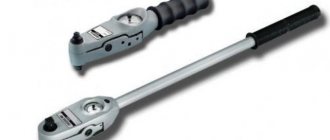
To prevent the camshafts from turning when turning out the bolts securing the camshaft toothed pulleys, we recommend using the device shown in the photo.
| Note The pulleys of the intake and exhaust camshafts have the same mounting dimensions, but a disk is attached to the pulley of the intake camshaft, which ensures the operation of the phase sensor. |
32. Using a 15mm wrench, unscrew the fastening bolt and remove the tension roller.
| Note Please note that there is a spacer ring installed under the roller. |
| 33. Using a 15mm wrench, unscrew the fastening bolt and remove the support roller. | 34. Using a 10mm wrench, unscrew the five bolts securing the rear protective cover of the timing belt... |
35. ...and remove the cover.
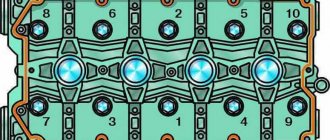
| . Tightening procedure for cylinder head bolts |
36. Using a 10mm hex key, unscrew the bolts securing the cylinder head to the cylinder block in the reverse order of tightening ( )…
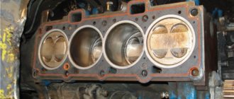
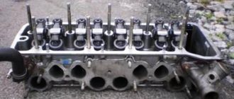
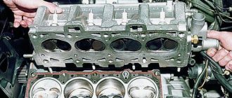
37. ...and remove the cylinder head from the engine.
| Warning Do not drive a screwdriver or other tools between the cylinder head and the cylinder block. |
| Useful tips It is more convenient to remove the cylinder head with an assistant, since it is quite heavy. |
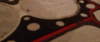
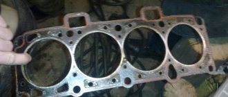
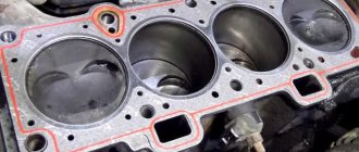
38. Remove the head gasket.
| Note The cylinder head bolts become stretched with repeated use. Replace bolts whose length (excluding head height) exceeds 98 mm with new ones. Before installing the cylinder head, lubricate the bolts with a thin layer of engine oil. |
| 39. Clean the mating surfaces of the cylinder head and cylinder block (they must be dry and clean). | 40. Remove oil from the threaded holes in the block for the head bolts. |
| Warning If you do not remove the oil from the threaded holes for the head bolts, cracks may appear in the cylinder block when the bolts are tightened, since the oil is not compressed. |
| 41. Check the presence of two installation sleeves in the sockets of the outer holes of the cylinder block for the head bolts. If, when removing the head, the bushings remain in the head or come out of the block sockets, press them into the block until they stop. | 42. Install a new head gasket on the block. Used gaskets are not permitted. Before installing the gasket, it is necessary to remove oil from the mating surfaces of the block and its head. The gasket must be clean and dry. Oil should not come into contact with the surface of the gasket. |
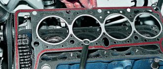
43. Install the head on the block, first making sure that the crankshaft and camshafts are in the TDC position (both valves of the 1st cylinder must be closed). Tighten the cylinder head bolts in the sequence shown in four stages:
1st - torque 20 N m (2 kgf m);
2nd - torque 69.4–85.7 N m (7.1–8.7 kgf m);
3rd - tighten the bolts 90°;
4th - finally tighten the bolts 90°.
44. Install the removed parts onto the cylinder head and connect hoses and wires to it in the reverse order of removal. Install the intake camshaft pulley with the disk that ensures the operation of the phase sensor towards the engine. Install the exhaust camshaft pulley in the same way. Adjust the tension of the timing belt (see “Replacing the timing belt and tension roller” , page 81) and the generator drive belt (see “Checking the tension of the generator drive belt” ).
| Note Before installing the cylinder head cover, apply Loctite-574 sealant to the camshaft bearing housing. It is allowed to start the engine no earlier than 1 hour after applying the sealant. |
↓ Comments ↓
1. Car structure
1.0 Car structure 1.1 General information about the car 1.2 Passport data 1.3 Car keys 1.4. Controls 1.5. Heating and ventilation of the cabin 1.6 Ensuring a comfortable air temperature in the cabin 1.7. Doors 1.8. Passive safety equipment on the car 1.9. Seats
2. Recommendations for use
2.0 Recommendations for use 2.1. Safety rules and recommendations 2.2 Running in the car 2.3 Operating the car during the warranty period 2.4. Preparing the car for departure
3. Problems along the way
3.0 Malfunctions along the way 3.1. The engine does not start 3.2 Malfunctions of the fuel injection system 3.3 Idle speed has disappeared 3.4. Interruptions in the operation of the 3.5 engine. The car moves jerkily 3.6 The car accelerates poorly 3.7 The engine stalled while driving 3.8. Oil pressure dropped to 3.9. Engine overheating 3.10. The battery does not recharge 3.13. Knocks in the engine 3.16. Wheel puncture
4. Maintenance
4.0 Maintenance 4.1. General provisions 4.2. Inspection work 4.3. Lubrication and filling works 4.4. Diagnostic work 4.5. Repair and adjustment work
5. Engine
5.0 Engine 5.1 Design features 5.2 Possible engine malfunctions, their causes and solutions 5.3 Useful tips 5.4 Checking compression in the cylinders 5.5 Removing and installing the decorative engine casing 5.6 Removing and installing the engine splash guard 5.7 Installing the piston of the first cylinder to the TDC position of the compression stroke 5.8 Replacing the drive belt gas distribution mechanism and tension roller 5.9 Replacing the power unit supports 5.11. Replacing engine seals 5.13. Engine cylinder head 5.15. Engine repair 5.16. Lubrication system 5.17. Cooling system 5.18. Power supply system 5.19. Design Features
6. Transmission
6.0 Transmission 6.1. Clutch 6.2. Gearbox 6.3. Front wheel drives
7. Chassis
7.0 Chassis 7.1. Front suspension 7.2. Rear suspension
8. Steering
8.0 Steering 8.1 Design features 8.2 Possible steering malfunctions, their causes and solutions 8.3. Steering column 8.4. Steering linkage 8.5. Steering gear
9. Brake system
9.0 Brake system 9.1 Design features 9.2 Possible malfunctions of the brake system, their causes and solutions 9.3 Bleeding the brake system hydraulic drive 9.4 Removing and installing the vacuum brake booster 9.5 Replacing the brake pedal axle bushings 9.6. Main brake cylinder 9.7. Front wheel brakes 9.8. Braking mechanisms of the rear wheels 9.9. Pressure regulator 9.10. Brake hoses and tubes 9.11. Parking brake
10. Electrical equipment
10.0 Electrical equipment 10.1 Design features 10.2. Battery 10.3. Mounting block (relays and fuses) 10.4. Generator 10.5. Starter 10.6. Ignition switch (lock) 10.7. Electronic engine control system (ECM) 10.8. Ignition system 10.9. Lighting, light and sound signaling 10.10. Windshield cleaner 10.11. Washer reservoir 10.12. Electric fan of the engine cooling system 10.13. Electric motor of the heating and ventilation system fan 10.15. Cigarette lighter 10.16. Instrument cluster 10.18. Electronic anti-theft remote control system 10.19. Immobilizer 10.21. Replacing sensors and switches
11. Body
11.0 Body 11.1 Design features 11.2 Possible body malfunctions, their causes and solutions 11.3 Removing and installing windshield frame lining 11.4 Removing and installing soundproofing upholstery in the engine compartment 11.5. Removing and installing bumpers 11.6 Removing and installing the fender liner and protective wing cover 11.7 Removing and installing the front fender 11.8 Removing and installing decorative sill trims 11.9. Hood 11.10. Trunk lid 11.11. Doors 11.12. Seats 11.13. Seat belts 11.14. Rear view mirrors 11.15. Interior fittings 11.16. Instrument panel 11.17. Heater 11.20. Body care
12. Applications
12.0 Appendix 12.1 Appendix 1. Tightening torques of threaded connections, Nm 12.2 Appendix 2. Fuels, lubricants and operating fluids 12.3 Appendix 3. Nominal filling volumes 12.4 Appendix 4. Basic data for adjustments and monitoring 12.5 Appendix 5. Spark plugs used on vehicles 12.6 Appendix 6. Lamps used on a car 12.7 Appendix 7. What you need to have in a car 12.8 Appendix 8. Tools used when repairing a car
13. Electrical diagrams
13.0 Electrical Diagrams 13.1 Diagram 1. Instrument Panel Harness Connections 13.2 Diagram 2. Vehicle Front Wire Harness Connections 13.3 Diagram 3. Engine Electronic Control System (ECM) Harness Connections 13.4 Diagram 4. Vehicle Rear Wire Harness Connections 13.5 Diagram 5. Light Harness Connections license plate light 13.6 Diagram 6. Left front door wiring harness connections 13.7 Diagram 7. Right front door wiring harness connections 13.8 Diagram 8. Rear door wiring harness connections
In what cases is it necessary to tighten the block?
During the operation of any car, including the VAZ 2170 Priora, the engine head is exposed to long-term cyclic effects of gases located in the engine cylinders. On older power units, the tightening of the cylinder head screws could weaken under such loads and periodically needed to be brought to a normal level. Today, all VAZ Priora engines use bolts made of special steel, which are tightened once for their entire service life.
If a coolant and oil leak occurs, there is no point in further tightening and tightening these bolts, since this will not improve the tightness of the joint. The only correct way to combat a leak is to remove the head, check the evenness of the mating surfaces and replace the gasket. After performing any repair work related to removing the head from the engine, it must be tightened in compliance with all necessary conditions.
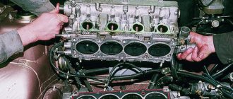
The video from the author Alex ZW shows the process of installing the cylinder head on an 8-valve engine.
Cylinder head repair
We mark all hydraulic compensators with numbers using an ordinary clerical touch and put them away. An ordinary magnet will help you pull them out. We dry out the valves and remove the oil seals (valve seals), the valves into scrap metal, the oil seals into the trash. We clean all channels. We take the head for grinding, just in case. After washing it again with kerosene after sanding and blowing it with air, we begin to assemble it.
We arrange the freshly purchased valves in the sequence in which they will stand in the cylinder head and begin to grind in one by one. Lubricate the valve stem with clean oil and apply lapping paste to the edge.
We insert the valve into place and put a valve grinding tool on the valve stem. The stores sell a device for manual lapping, but since this is the twenty-first century, we are mechanizing the process. We take the old valve and cut off the rod from it, select a rubber tube for it of such a diameter that it fits tightly. The rod is in a reversible drill, one end of the tube is on it, the other is on the valve being ground in. At low speeds we begin to grind the valve, constantly change the direction of rotation and periodically press it to the seat or weaken the force. On average, the valve takes about twenty seconds. We take it out and wipe it. The valve is considered ground in if a uniform gray strip of at least 1.5 mm wide appears on the chamfer.
The same stripe should appear on the valve seat.
Video of manually grinding valves
For a sixteen valve head, everything is the same, only there are twice as many valves.
After lapping, all valves and seats are thoroughly wiped and washed with kerosene to remove any remaining lapping paste. We check for leaks. We tighten the old spark plugs and put all the valves in place. Pour kerosene and wait three minutes, if the kerosene does not run away all is well, otherwise we grind the valves on this cylinder.
We had to grind four valves again, after which the kerosene stopped flowing.
We stuff new valve seals.
We put the valves in place and dry them. Before doing this, lubricate the valve stems with clean oil. After lubricating it with clean oil, we put the hydraulic compensators in place and, covering them with a clean cloth, remove the head out of sight. We're done with the cylinder head.
Reasons for gasket burnout
There are few reasons why a cylinder head gasket burns out, but with a new engine there is only one – overheating. Even a short time of engine operation at temperatures above normal can cause this malfunction. In this case, the gasket may burn out quite a bit, and inexperienced motorists will not notice the first symptoms that appear. With further operation, the burnout increases, and the symptoms become more pronounced. Due to the fact that many car owners turn to specialists not after overheating, but after some time of operation, when the malfunction becomes a clear fact, they do not connect the burnout of the gasket with the recent overheating and demand from motorists other explanations why the cylinder head gasket burned out.
If the volume of coolant is insufficient, you may not notice a slight overheating of the head, since the liquid, circulating in the system, manages to cool in the radiator, but does not have time to remove heat in the required amount. Instruments in a car show the temperature of the coolant, not the temperature of the engine parts. Thus, when operating a car with an insufficient level of antifreeze, you can burn the gasket without realizing that the cause was overheating.
Burnouts occur due to poor-quality gaskets, but this mostly applies to engines after repair. This happens extremely rarely on new cars. Even on repair engines, the cause of such a malfunction may be factors related to the quality of the repairs performed:
- unsatisfactory condition of the mating surfaces (remains of the old gasket, shells or scratches on the surfaces are poorly cleaned, head deformation);
- incorrect tightening torque of the cylinder head bolts;
- the order of tightening the cylinder head bolts is incorrect;
- the thickness of the gasket is incorrectly selected (on engines where they come in different sizes).
Malfunctions
At the same time, it must be said that this power unit is not without characteristic shortcomings that require the car owner to pay attention to certain engine components.
For example, there may be problems with engine power, which is caused by loss of tightness of the fuel system and improper operation of the air mixture sensors.
Another typical problem is a change in valve geometry, which occurs due to incorrectly calculated operation of the pistons. Experts recommend replacing the pistons with non-stick pistons after a mileage of 50-100 thousand kilometers, which will solve this problem.
| FAULTS | CAUSES AND REMEDIES |
| Significant reduction in power of the power unit. | Such a drop in VAZ 21126 engine power may occur due to problems with the injector or problems with the air flow meter. |