generation Skoda Octavia A5 . It was produced in 2004, 2005, 2006, 2007, 2008, 2009, 2010, 2011, 2012 and 2013 with station wagon and liftback bodies, with both gasoline and diesel engines. In this material we will provide a description of the fuse and relay blocks of the Skoda Octavia A5 (MK2) , their locations, photographs and diagrams. We will separately highlight the fuses responsible for the cigarette lighter and washer. In conclusion, we will offer a complete electrical diagram of the car for download.
The number of elements in the block and their purpose may differ from those presented and depend on the year of manufacture, the level of equipment of the car and the country of delivery.
PSU installation locations and access to them
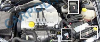
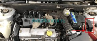
The Skoda Octavia A5, like most cars, is equipped with two safety modules: in the passenger compartment and in the engine compartment of the car. It won't take much time to get to them. If you need to inspect the fuses in the engine compartment, you just need to open the car hood and secure it.
- The safety block is located on the right near the shock absorber strut, if you stand in front of the car and look directly at it.
- Access to the fuses is as follows: you need to slide two latches on the plastic cover and pull it towards you.
- After which all protective devices and two relays are opened, providing control of the operation of the cooling fan and control of the Skoda Octavia A5 automatic transmission.
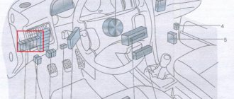
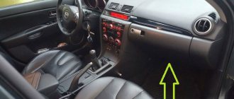
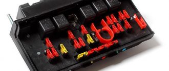
The power supply installed in the car is located near the driver in the dashboard. Once you open the driver's door, you can see a cover at the end of the front panel covering the fuse module. Using a flat screwdriver, the cover is pryed up and removed.
Wiring diagrams Skoda Octavia 2
Still have questions? Study the electrical diagrams of the Skoda Octavia A5: “download” or ask them in the comments.
The recording is for yourself, but it will definitely be useful for someone, so that the information is always at hand, in case of force majeure. Before replacing any fuse, turn off the ignition! Remove the cover with a screwdriver. There are tweezers inside for convenience. A burnt-out metal wire is visible in a blown fuse.
Designation in colors Color Max. current in amperes light brown 5 dark brown 7.5 red 10 blue 15 yellow 20 white 25 green 30 orange 40 red 50
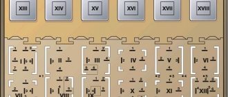
Assignment of fuses in the front panel of the Skoda Octavia A5
| № | Consumer |
| 1 | Diagnostic connector, engine control unit, fuel pump |
| 2 | ABS, ESC control unit |
| 3 | Airbags |
| 4 | Heating, air conditioning, reversing lights |
| 5 | Headlight range control unit |
| 6 | Instrument cluster, automatic transmission control unit, electromechanical power steering control unit, parking aid |
| 7-11 | Not used |
| 12 | Central locking control unit |
| 13 | Diagnostic connector, light switch |
| 14 | Automatic transmission control unit, selector lever lock |
| 15 | On-board power supply control unit - interior lamps |
| 16 | Climatronic |
| 17 | Not used |
| 18 | Rear window wiper |
| 19 | Trailer recognition control unit |
| 20 | Not used |
| 21 | Adaptive lighting, left and right sides |
| 22 | Climatronic fan |
| 23 | Front door windows |
| 24 | Cigarette lighter |
| 25 | Heated rear window, auxiliary heater and fan |
| 26 | Socket in luggage compartment |
| 27 | Fuel pump, injectors (diesel engine) |
| 28 | Head device |
| 29 | Engine control unit, crankcase ventilation heating |
| 30 | Automatic transmission control unit, Haldex |
| 31 | Vacuum pump |
| 32 | Rear door windows |
| 33 | Electric tilt-and-slide sunroof |
| 34 | Comfort system control unit |
| 35 | Alert |
| 36 | headlight washer |
| 37 | Heated front seats |
| 38 | Heated rear seats |
| 39 | Instrument cluster, wiper arm and turn signal switch |
| 40 | Heater and air conditioning fan |
| 41-42 | Not used |
| 43-45 | Towbar |
| 46 | Heated seats |
| 47 | Autonomous heating and ventilation |
| 48 | Telephone |
| 49 | Light switch |
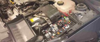
To gain access to the mounting block located in the engine compartment and unlock the fuse box cover, move the clamps all the way down.
open lock icon will be visible on the back of the bracket/retainer . Now remove the cover. After replacing the fuse, install the cover on the fuse block and slide the locking lever all the way back. closed lock icon will be visible on the back of the bracket - the lid is locked.
Fuses and relays under the hood of Skoda Octavia A5
The mounting block in the engine compartment is located on the driver's side, near the fender.
Fuse box diagram in the engine compartment of the Skoda Octavia A5
Description
| Fuse/relay number | Current strength, A | Protected circuit |
| 1 | — | Reserve |
| 2 | 5 | Steering column switches |
| 3 | 5 | Diagnostic connector |
| 4 | 30 | Hydroelectronic ABS module |
| 5 | 15 | Automatic transmission control unit |
| 6 | 5 | Instrument cluster |
| 7 | — | Reserve |
| 8 | 15 | Audio system |
| 9 | 5 | Telephone |
| 10 | 5 | Engine control unit relay power supply |
| 11 | 20 | Additional heating and ventilation control unit |
| 12 | 5 | Data bus control unit |
| 13 | 15 | The engine control unit |
| 14 | 20 | Ignition |
| 15 | 5, 15 | Oxygen concentration sensor, fuel pump relay, glow plug relay |
| 16 | 30 | ABS control unit |
| 17 | 15 | Sound signal |
| 18 | 30 | Amplifier |
| 19 | 30 | Windshield wipers |
| 20 | — | Reserve |
| 21 | 15 | Oxygen concentration sensor |
| 22 | 5 | Clutch pedal switchDormosa |
| 23 | 5, 10, 15 | Additional air pump, injection pump, mass air flow sensor |
| 24 | 10 | Exhaust gas recirculation valve |
| 25 | 30 | Right headlight |
| 26 | 30 | Left headlight |
| 27 | 40 | Additional air pump, preheating |
| 28 | 40 | Starter |
| 29 | 50 | Clamp power 30 |
| 30 | 50 | Terminal X - Equipment connected to this terminal is automatically turned on when the engine starts. |
| R1 | — | Radiator Fan Motor Relay |
| R2 | Automatic transmission control relay |
Location of fuses in the engine compartment of the Skoda Octavia A5
PURPOSE OF FUSES IN THE INSTALLATION BLOCK LOCATED IN THE ENGINE COMPARTMENT OF THE CAR
| № | Consumer |
| F1 | Not used |
| F2 | Automatic transmission control unit |
| F3 | Test lead |
| F4 | ABS valves |
| F5 | Automatic transmission control unit |
| F6 | Instrument cluster, wiper arm and turn signal switch |
| F7 | Terminal 15 power supply, starter |
| F8 | Head device |
| F9 | Not used |
| F10 | Engine control unit |
| F11 | Autonomous heating and ventilation control unit |
| F12 | Data bus control unit |
| F13 | Engine control unit |
| F14 | Ignition |
| F15 | Lambda probe, pre-glow system |
| F16 | Onboard power supply control unit, right headlight, right rear light |
| F17 | Sound signal |
| F18 | Digital Audio Processor Amplifier |
| F19 | Windshield wiper |
| F20 | Coolant pump, fuel metering valve |
| F21 | Lambda probe |
| F22 | Clutch pedal switch, brake pedal switch |
| F23 | secondary air pump, air flow meter, high pressure fuel pump |
| F24 | Canister, EGR valve, radiator fan |
| F25 | ABS pump |
| F26 | Onboard power supply control unit, left headlight, left rear light |
| F27 | Secondary air pump, pre-glow system |
| F28 | Not used |
| F29 | Terminal 30 power supply |
| F30 | Terminal Xa) |
Skoda Octavia fuse box: markings, pinout, location
Vehicle fuses are designed to prevent electrical short circuits and possible vehicle fire. The Skoda Octavia has two locations: the interior and under the hood. The failure of one of the elements means that the circuit opens and the corresponding element must be replaced.
Interior fuses
The layout of the fuses in the mounting block, which is located on the Octavia:
| Number | Current strength, A | Color | Purpose of the fuse |
| 1 | 10 | Red | Heated mirrors, cigarette lighter relay |
| 2 | 10 | Red | Direction indicators |
| 3 | 5 | Light brown | Glove compartment lamp |
| 4 | 5 | Light brown | License plate lamps |
| 5 | 7,5 | Brown | Heated seats, heated exterior mirrors |
| 6 | 5 | Light brown | Central locking control unit |
| 7 | 10 | Red | Tail lights, parking assist sensors |
| 8 | 5 | Light brown | Telephone |
| 9 | 5 | Light brown | ABS, ESP control unit |
| 10 | 10 | Red | Ignition |
| 11 | 5 | Light brown | Instrument cluster |
| 12 | 7,5 | Brown | Diagnostic connector |
| 13 | 10 | Red | Brake lights |
| 14 | 10 | Red | Interior lighting control unit |
| 15 | 5 | Light brown | Instrument cluster |
| 16 | 10 | Red | Air conditioner |
| 17 | 5/30 | Light brown/green | Heating of washer jets |
| 18 | 10 | Red | Right high beam lamp |
| 19 | 10 | Red | Left high beam lamp |
| 20 | 15 | Blue | Right low beam lamp, electric headlight leveler |
| 21 | 15 | Blue | Left low beam lamp |
| 22 | 5 | Light brown | Right tail light bulb |
| 23 | 5 | Light brown | Left tail light bulb |
| 24 | 20 | Yellow | Windshield wiper |
| 25 | 25 | White | Heating fan |
| 26 | 25 | White | Heated tailgate glass |
| 27 | 15 | Blue | Tailgate glass wiper |
| 28 | 15 | Blue | Fuel pump relay |
| 29 | 15/10 | Blue red | Electronic engine control unit |
| 30 | 20 | Yellow | Electric sunroof |
| 31 | — | — | Reserve |
| 32 | 10,30 | Red Green | Fuel injectors |
| 33 | 20 | Yellow | Headlight washers |
| 34 | 10 | Red | Electronic engine control unit |
| 35 | 30 | Green | Power socket in trunk |
| 36 | 15 | Blue | Fog lights |
| 37 | 20/5 | Yellow/light brown | Electronic engine control unit |
| 38 | 15 | Blue | Central locking control unit, luggage compartment lamp |
| 39 | 15 | Blue | Hazard warning lights |
| 40 | 20 | Yellow | Sound signal |
| 41 | 15 | Blue | Cigarette lighter fuse for Skoda Octavia |
| 42 | 15 | Blue | system, phone |
| 43 | 10 | Red | Electronic engine control unit |
| 44 | 15 | Blue | Seat heating |
| RES | — | — | Reserve |
Description of fuses for the Skoda Octavia Tour: location, diagram, price
Marking / amperageWhat it is responsible for (with description)
| F (F-1) / 20 | High beam right |
| F (F-2) / 5 | –/– left |
| F (F-3) / 10 | Front fog lamp left |
| F (F-4) / 10 | –/– right |
| F (F-5) / 20 | Heated seats, heater fan |
| F (F-6) / 30 | ABS |
| F (F-7) / 30 | Signal, trunk, cigarette lighter, transmission, diagnostic connector |
| F (F-8) / 7.5 | Fuel pump (gasoline pump) |
| F (F-9) / 10 | central locking |
| F (F-10) / 10 | Daytime Running Lights |
| F (F-11) / 10 | Air conditioning system |
| F (F-12) / 10 | Interior lighting, brake light |
| F (F-13) / 30 | ABS optional |
| F (F-14) / 30 | Reserved |
| F (F-15) / 10 | Reserved |
| F (F-16) / 15 | Reserved |
| F (F-17) / 15 | Reserved |
| F (F-18) / 10 | Heated windshield, radio, generator |
| F (F-19) / 10 | Furnace heater, electric power steering |
| F (F-20) / 10 | Electronic engine control unit, cooling system, ignition coils, fuel injectors |
| F (F-21) / 5 | Electric window drive |
| F (F-22) / 5 | Emergency crew |
| F (F-23) / 5 | Windshield wiper, front airbag |
| F (F-24) / 5 | Egnition lock |
| F (F-25) / 5 | Reverse gear |
| F (F-26) / 5 | Adsorber, oxygen flow sensor, speed sensor |
| F (F-27) / 20 | Heated rear window |
| F (F-28) / 15 | Right clearance |
| F (F-29) / 15 | Left clearance |
| F (F-30) / 20 | Rear fog lamp |
| F (F-31) / 15 | Low beam left |
| F (F-32) / 15 | –/– right |
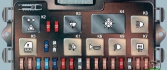
Fuses in a mounting block installed in the engine compartment of a Skoda Octavia Tour car
DesignationWhich is responsible for what/what provides
| K 1 | Who is responsible for what/what provides |
| K2 | Heated rear window |
| K 3 | Powertrain control module relay |
| K 4 | Fuel pump relay |
| K5 | Reserved |
| K 6 | Additional cooling fan relay |
| K 7 | Heated windshield (main) |
| K 8 | –/– (optional) |
| K9 | Air conditioning system |
| K 10 | Electric cooling fan |
| K11 | central locking |
| K 12 | Starter (optional) |
| K 13 | Ignition switch core contacts |
| K 14 | Reserved |
| K 15 | Windshield wiper (wipers) |
| K 16 | For headlights, high beam optics |
| K 17 | Sound notification |
The cost of a set of a new mounting block for the interior is from 2500 - 2800 rubles, for the engine compartment - from 2300 rubles. Individual modules from 200 – 250 rubles (originals), high-quality analogues from 180 rubles.
Characteristic signs of faulty fuses
- Mechanisms, equipment are inactive, the power circuit is not damaged, complete circuits, terminals, limit switches;
- The modules in the mounting block are heated, the temperature regime is unusual;
- The smell of melted plastic can be heard in the car interior and engine compartment;
- An indicator on the dashboard indicates a malfunction in the equipment;
- The car engine does not start.
Typical causes of fuse failure
- Failure to comply with the deadlines for scheduled technical inspections and replacement of worn-out elements;
- Purchase of non-original consumables (modules);
- Violation of installation technology;
- Mechanical damage to the mounting block;
- Short circuit in the electrical circuit;
- Damage to insulation, terminals, power cable ends;
- Terminal oxidation;
- Weak contact fixation;
- Formation (accumulation) of moisture and condensation, which caused a short circuit in the circuit and equipment breakdown.
Cigarette lighter Skoda Octavia A7: replacing the fuse
All modern cars are equipped with this device. Even non-smoking car owners use it. Instead of its intended purpose, the cigarette lighter socket is used as a standard 12-volt outlet for connecting electronic devices:
- tire inflation pump;
- electronic charger for a mobile phone or tablet;
- DVR monitoring the current traffic situation;
- a navigator that calculates a suitable road;
- portable lighting lamp;
- compact vacuum cleaner;
- fan.
A cigarette lighter failure can lead to some hassle or inconvenience. To avoid them, you should know how to replace or repair the cigarette lighter on a Skoda Octavia A7 or A5.
The design and principle of operation of the cigarette lighter
The device is made as follows. The cigarette lighter device is similar for all Skoda models, including Fabia, Rapid or Octavia. Inside the front panel there is a metal socket to which three wires are connected.
- Main plus (red). Comes to the battery through a protective element (fuse). Responsible for heating the internal spiral.
- Constant plus (yellow). Connected to a light filter. Responsible for the correct operation of the backlight.
- Constant minus (black). A mass with one end coming to the body of the device, and the other to the body of the car.
The Octavia A7 cigarette lighter itself is inserted into the connector, inside of which there is a metal spiral. When you press the button, the contacts close and the spiral is exposed to thermal effects. As soon as it heats up to a temperature sufficient to light a cigarette, a special thermal relay snaps the device into its initial position.
Causes of cigarette lighter malfunction
Over time, the device may fail. There are several reasons why you need to remove and repair the cigarette lighter on the Skoda Octavia A7.
- Blown fuse. The cigarette lighter safety element is a switch that protects the wires from melting or fire in the event of a short circuit. Each section of the electrical circuit School Octavia A7 is designed for a certain current strength. If the maximum value is exceeded, the cigarette lighter fuse blows. You need to get to the mounting block and change the element. The cigarette lighter fuse of the Skoda Octavia A7 with index F24, rated 25 amperes, must be replaced.
- Short circuit. If the new cigarette lighter fuse on the Skoda Octavia A7 has burned out again, then there is a high probability that the wires are shorted. It is necessary to open the engine compartment and check the battery voltage with the ignition off. Then we turn it on and check the voltage again using a tester. If there is a drawdown of more than 0.5 volts, then a “short one” is walking along the circuit.
- It is necessary to inspect all wires: there should be no kinks or breaks, the insulation must be intact and not melted. It is worth checking all the cigarette lighter wires for breaks. We take a tester and then check the cables for resistance. If a break is detected, solder the wire or replace it with a new one.
- Unreliable contacts. Over time, the fixing antennae become loose due to the constant connection of foreign devices, and plaque may form on the contacts themselves. It is not necessary to change the cigarette lighter on the Skoda Octavia A7 - just clean the contacts with a file or sandpaper and bend them for reliable fixation.
- Burnt out cigarette lighter coil. A thin nichrome thread is installed inside the device, which is constantly heated and cooled. Over time, it may burn out. Repairing it is impractical - it is advisable to install a new cigarette lighter on the Octavia A7.
- Faulty backlight bulb. Especially for searching for a socket in the dark, the cigarette lighter on the Octavia A7 has a light filter. The light bulb located inside may burn out. It is necessary to disassemble the device and replace the burnt out element.
Replacing the fuse
One of the most common cigarette lighter failures is the failure of the protective element. In this case, you need to get to the Skoda Octavia fuse box and change the burnt out element. One block is located in the engine compartment: the main relays, fuses for the lambda probe, horn, etc. are located there.
We are interested in the set that is located in the interior of the Octavia A7 car. It is located on the left side of the front panel, behind the decorative cover. To get to it, you need to open the door and disconnect the plastic latches by prying them off with a screwdriver. On the reverse side there is a diagram of the elements:
| Number | Amperage | Purpose |
| 1 | 10 | Diagnostic connector, ECU, fuel pump |
| 2 | 5 | Anti-lock and traction control unit |
| 3 | 5 | Airbags |
| 4 | 5 | Heater, climate control, reverse signal lamps |
| 5 | 5 | Instrument panel combination, power steering |
| 12 | 10 | Central lock |
| 13 | 10 | Stop signals |
| 14 | 5 | Automatic transmission selector lock |
| 15 | 7,5 | Interior lamp |
| 16 | 10 | Climate control unit |
| 18 | 5 | Parktronic |
| 19 | 5 | Towbar |
| 20 | 5 | Hill start assist systems |
| 22 | 40 | Fan |
| 23 | 30 | Electric windows |
| 24 | 25 | Cigarette lighter |
| 25 | 30 | Rear window heating element |
| 26 | 20 | 12-volt power outlet in trunk |
| 27 | 15 | Fuel injectors, fuel pump relay |
| 29 | 10 | Engine ECU |
| 30 | 20 | Transmission control unit |
| 31 | 20 | Vacuum pump for brake circuits |
| 32 | 30 | Rear electric windows |
| 33 | 25 | Sunroof |
| 34 | 20 | Comfort ECU |
| 35 | 5 | Signaling |
| 36 | 20 | Headlight washers |
| 37 | 20 | Heating elements for front seats |
| 38 | 30 | Rear seat heating elements |
| 40 | 40 | Heater fan |
| 41 | 15 | Rear window wiper |
| 42 | 15 | Windshield wiper |
| 43 | 15 | TSU |
| 44 | 15 | TSU |
| 45 | 15 | TSU |
| 46 | 5 | Jet heating |
| 47 | 5 | Backup heater relay |
| 49 | 5 | Light switch |
Fuse box in the passenger compartment
When you open the driver's door completely, you can see the cover at the end of the dashboard, behind which there is a cabin power supply. Opening the lid is easy; just use a flat-head screwdriver.
Engine compartment fuse box
In the Skoda Octavia car, the fuse box installed in the engine compartment near the right wing is covered with a protective cover. In order to unlock it, you need to move the latches.
By removing the cover, you can gain access to the fuses and relays that protect the components located under the hood.
The decoding of the protected electrical circuits of the on-board network of the Skoda Octavia TUR/A5 is given in the table:
Purpose
The installation diagram for fuses and relays is quite extensive, so in order to know which device is responsible for what, you need to familiarize yourself with their features. So, for example, the 5-amp elements of the mounting block in the car interior are responsible for the correct operation:
- ABS and ESC systems;
- driver and passenger airbags;
- climate control and heating systems;
- automatic gearbox;
- rear window wiper electric motor;
- heated front and rear seats.
10-amp are responsible for:
- car central locking;
- switches for external and internal lighting;
- cigarette lighter;
- engine control.
20-amp controls the sockets in the luggage compartment and the windshield and headlight washers of the car.
Fuse box under the hood
We open the hood and the second block is located on the upper right side of the engine. Remove the block cover by moving both brackets down and pulling the cover towards you until it moves away from the body.
In addition to fuses, the module contains relays.
RelayPurpose
| R1 | Radiator Fan Motor |
| R2 | Automatic transmission control |
Engine compartment mounting block
| Denomination, A | Protect |
| Circuits of diagnostic wires, turn signal and windshield wiper levers, powertrain control module, clutch pedal switch | |
| Used in cooling fan, exhaust gas circulation valve, secondary air pump and fuel pump circuits | |
| Circuit of lambda probe, horn, automatic transmission control unit, trunk light | |
| Ignition, on-board power supply and right lighting control module | |
| Higher load circuits such as starter, power terminals, ABS valves |
Relay block
It is located under the instrument panel itself, behind the trim panel.
Option 1
Scheme
Designation
- B4 - supply voltage relay (30)
- B5 - rear window heating relay
- B6 - horn relay
- B7 - relay -1- glass washer pump
- B8 - relay -2- glass washer pump
- B9 - switching relay for contact X
Option 2
In this version, there is also a central control unit.
Relay block for central control unit
Scheme
Purpose
- Supply voltage relay (15) -J329-
- Relay for heated rear window -J9-
- supply voltage relay (50) -J682- / starter relay 1 -J906-
- Fuel pump relay (pressure build-up) -J643- (for engine codes BUD, CGGA, BSE, BSF, CMXA, CHGA) / fuel pump relay -J17- (for diesel engines)
- Switching relay for contact X -J59-
Additional relay block above the central control unit
Decoding
- D1 - Independent heater relay -J485- (for vehicles with an independent auxiliary heater) / relay for low heating output -J359- (for vehicles with an auxiliary resistive heater (PTC))
- D2.1 - Horn relay -J4-
- D2.2 - fuel pump relay (for engine codes BUD, CGGA, BSE, BSF, CMXA, CHGA) / - additional fuel pump relay -J832- (for engine codes CLCA, CLCB, CFHF, CFHC, CEGA)
- D3 - relay for high heating output -J360- (for vehicles with an additional resistance heater (PTC)) D3.1 - relay for the fresh air intake fan -J13- (for vehicles with an independent additional heater)
- D3.2 - Auxiliary heater fuel pump relay -J749- (for vehicles with independent auxiliary heater)
- D4 - Starter relay 2 -J907-
- D5.1 - headlight washer relay -J39
- D5.2 - relay for heating element -J925- (for engine code CAYC)
More information about the location, access, as well as a video example of removing the comfort block can be found in this video.
Is the stove not working? Some models have a thermal fuse for the stove, which is located separately.
Video example of its replacement.
Engine compartment mounting block
| Denomination, A | Protect |
| Circuits of diagnostic wires, turn signal and windshield wiper levers, powertrain control module, clutch pedal switch | |
| Used in cooling fan, exhaust gas circulation valve, secondary air pump and fuel pump circuits | |
| Circuit of lambda probe, horn, automatic transmission control unit, trunk light | |
| Ignition, on-board power supply and right lighting control module | |
| Higher load circuits such as starter, power terminals, ABS valves |
Replacing fuse links
Replacement of blown fuses is carried out in the following order:
- Turn off the ignition and turn off all energy-consuming devices.
- Open the cover of the Skoda Octavia TUR/A5 fuse box, which is installed in the engine compartment or inside the dashboard.
- Determine which of the fuse links has failed. This can be seen from the molten metal insert in the slot in its body.
- Check the associated electrical circuit for short circuit or overload. Important! It is forbidden to short-circuit the wires to the car body (“ground”), checking the integrity of the wiring for a “spark”. In addition, it is not recommended to use metal tools when working with fuses - you can accidentally cause a short circuit in a working circuit.
- Take plastic tweezers (located on the inside of the lid) and use it to remove the failed fuse-link from the seat.
- Using plastic tweezers, install a new fuse-link of the same rating in the appropriate seat. Attention! When replacing, it is not allowed to use fuses of a different rating, homemade “bugs” and fuses of a different design.
- If, after replacement, the new fuse link fails again, you must contact a certified service station to check the electrical equipment using appropriate equipment.
Replacement
- First you need to turn off the ignition, and it is best to remove the terminals from the battery.
- Carefully inspect the safety block for burnt-out inserts.
- Using tweezers, remove the old (faulty) fuse from the socket.
- The same tools are used to put a serviceable part in place.
Important! You cannot install new protective elements of a higher rating instead of the required ones. In this case, there is a risk of fire.
If, after installing a new protective device, it burns out, this means that the entire electrical circuit needs to be checked or there is a problem with the vehicle's electrical equipment.
Experienced drivers who have driven tens of thousands of kilometers always keep spare protective devices in the trunk for all occasions.
One electrical consumer can be protected by several fuses. One fuse can protect the circuits of several electrical consumers.
In general, the process of replacing the inserts of the Skoda Octavia A5 safety block is simple and any driver can do it independently. The main thing is to do everything on time. If the fault cannot be identified and eliminated, you should contact a service station.
Installing the glove box
- Hook the glove box onto the fasteners (A) (Fig. 214).
- Insert the glove box in the opposite direction of the arrow (4).
- Insert the stopper and lock it with a screwdriver in the opposite direction of the arrow (3).
- Insert the side cover in the opposite direction of the arrow (2).
- Press the side cover in the opposite direction of the arrow (1).
- Close the glove compartment.
Sources
- https://zapchasti.expert/predoxraniteli/predoxraniteli-skoda-octavia-a5.html
- https://www.avtopol-msk.ru/sxema-raspolozheniya-predoxranitelej-na-skoda.html
- https://vsepredohraniteli.ru/skoda/a5-octavija.html
- https://zapchasti.expert/predoxraniteli/predoxraniteli-skoda-octavia-tour.html
- https://fuse-box.ru/predohraniteli-i-rele-skoda-octavia-mk1-1u-1996-2010/
- https://razborov.net/shkoda/blok-predohraniteley-i-rele-skoda-oktavia-tour.html
- https://razborov.net/shkoda/predohraniteli-i-rele-skoda-octavia-a5.html
- https://angelcharlie.ru/predohraniteli-na-shkode-oktaviya-a7/
[collapse]
Skoda Octavia fuses (Skoda Octavia) Tour: where they are, replacement – Taxi Bolt
Skoda Octavia 1
generation was created on the
A4 . This car was produced in 1996, 1997, 1998, 1999, 2000, 2001, 2002, 2003 and 2004 with liftback and station wagon bodies. In some countries, production continued until 2010 under the name Octavia Tour . This generation was equipped with 1.4 1.6 1.8 2.0 liter gasoline engines and 1.9 liter diesel engines. This publication will provide a description of the fuses and relays of the 1st generation Skoda Octavia Tour, the location of the blocks, their diagrams and photographs. At the end we will offer an electrical diagram for downloading.